Electronics production
Assignment for this week
- Make the FabISP in-circuit programmer
- Mill the board
- Solder the components on the board
- Set it up for programming
- Link to this week’s home work page
This week lecture was about electronics production and our assignment was the fabrication of a PCB (FabISP) aimed at in-system programming AVR microcontrollers. At first, it seemed to me a bit odd to learn about PCB fabrication before learning the basics of electronic circuits and electronic circuit design but why not. Neil explained about the various way of producing PCBs (etching, milling, cutting), PCB materials, electronic parts (through-hole and SMD) and the way to solder parts on a PCB. In addition to the lecture we had the chance to listen to an introduction to PCB production by Eric Pan from Seeed. As this page is quite long, I used internal links. The page is organized as follows:
- The FabISP
- Making a board with chemical etching
- Making a board by CNC milling
- SMD part soldering
- Milling a FabISP with FabModules and MDX40
- Attempts to program the FabISP
- Update after 1st evaluation round
The FabISP
The objectif of this week was thus making this:
The objective of the week (photo from David Mellis' webpage).
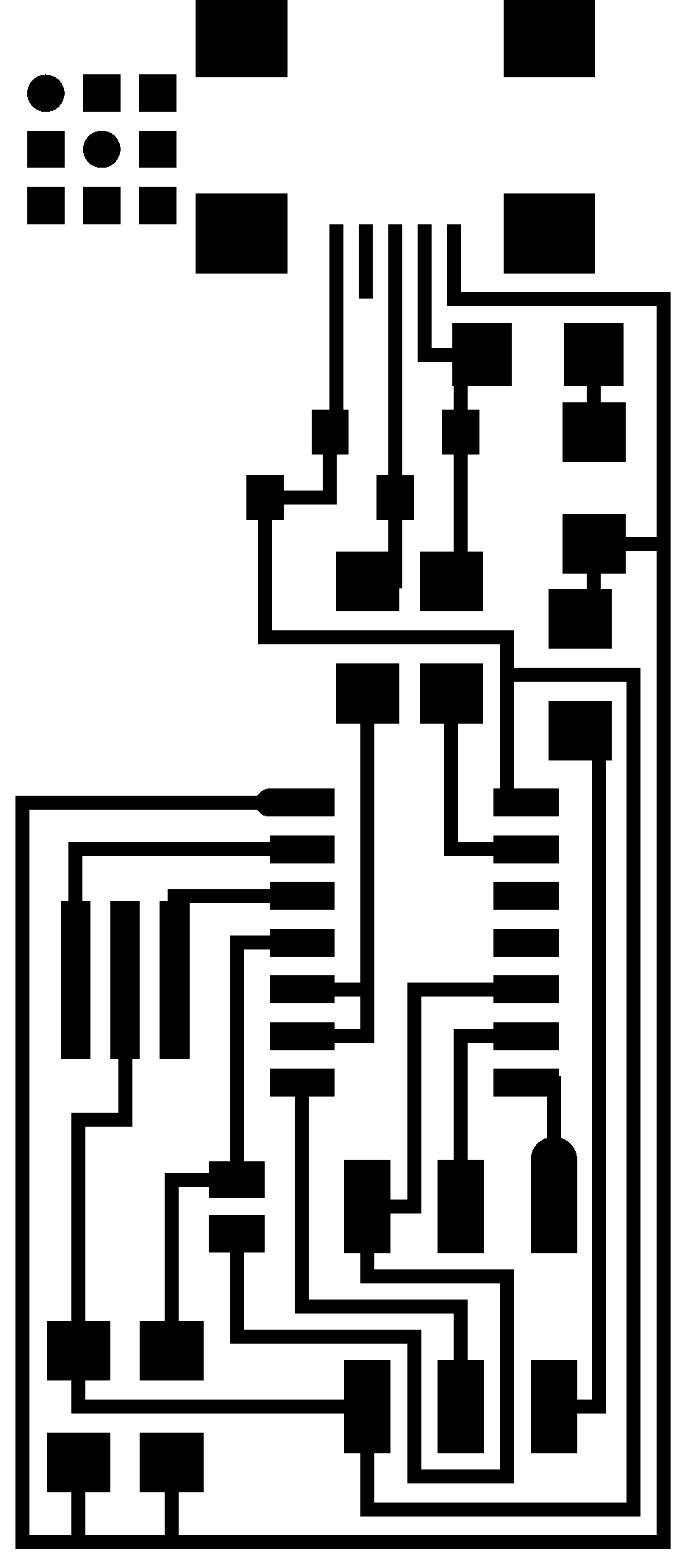
On the lecture's page, Neil provided links to pages with help on how to fabricate FabISP as well as png images of the board layout and traces


The old board layout and the traces provided by Neil plus the inverted traces used for chemical etching.


The new board layout and the traces provided by Neil plus the inverted traces used for chemical etching.
Making a board with chemical etching
Although Neil asked us to mill the PCB to avoid manipulation of chemical and because the miller is part of the Fablab inventory, I first used chemical etching because I already had some experience in that and I had access to the facility.
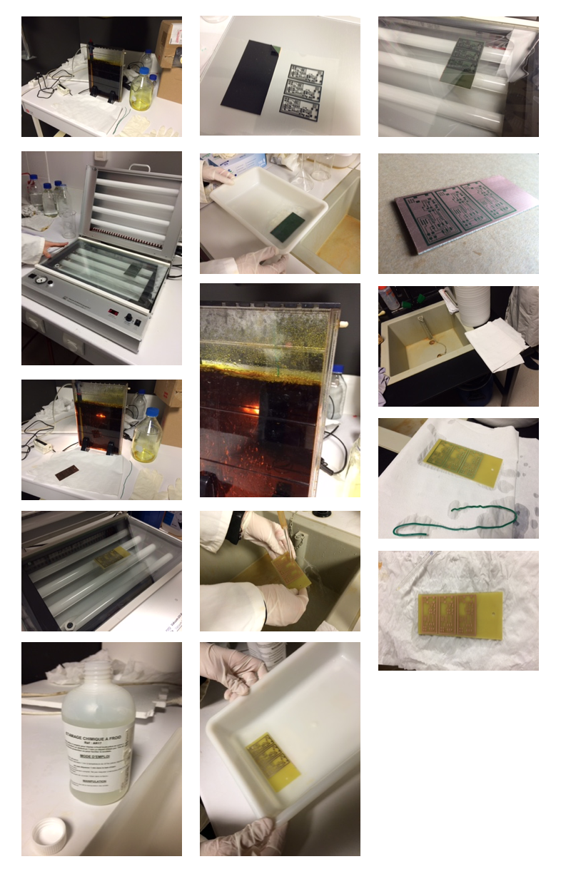
Several steps involved in the production of a PCB by chemical etching.
Chemical etching or chemical milling is a substractive manufactrugin process that involves different steps summarized below. The main idea is to remove the unwanted copper from a copper coated epoxy laminate sheet (FR4) using a chemical etchant (iron chloride). The sheets are generally coated with a photosensitive resist that can be removed by sodium hydroxide after proper UV exposition leaving unprotected copper ready to be etched.
- prepare the equipment and the chemicals
- print the mask on a transparency film
- remove the protection of the copper laminate and put the mask on it
- expose to UV light for 2 min
- remove the UV exposed resin by placing the laminate in a sodium hydroxide bath
- rinse with water
- suspend the laminate in an iron chloride bath and wait for 10-20 min
- rinse with water
- expose the laminate to UV light for 2 min without the mask
- remove the resin with sodium hydroxide
- rinse with water
- plunge the laminate in a cold tin bath for 10sec
- rinse with water
Making a board by CNC milling
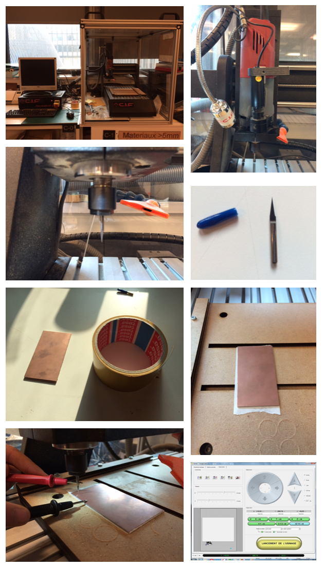
Since we did'nt have access to Roland Modela CNC milling machine in our lab in Paris (we need to schedule a lab session at digiscope to train with the fab modules) we tried to use our CNC milling machine (a Technodrill 2 from CIF).
EagleCAD and Gerber files
The first thing we needed to do is to obtain a Gerber file that could be imported in the Technodrill software. We used the EagleCAD files .sch and .brd found in the student archive and use Eagle CAM processor to produce a valid Gerber file.
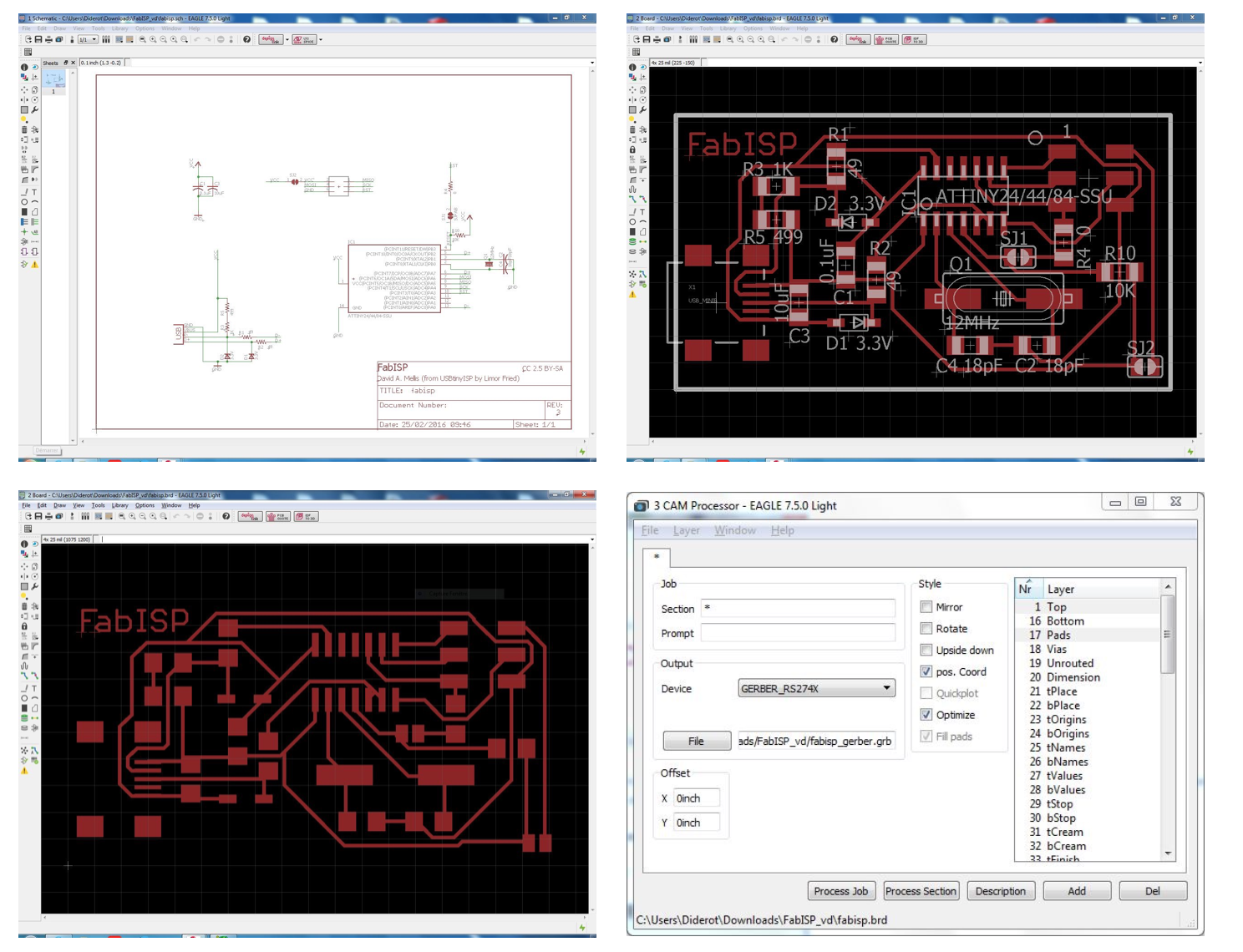
Technodrill software: Percival and Galaad
We then imported the Gerber file the technodrill software (Percival/Galaad) that is used to calculate the tool path for CNC milling.
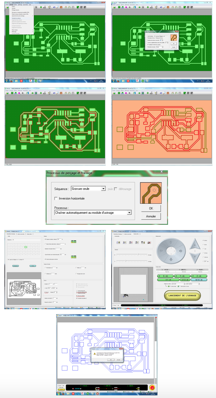
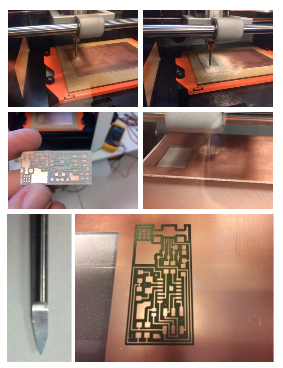
Milling
The next important step was setting the x,y origin and more importantly the z origin. Indeed, the quality of the milling depends on this setting and on the depth specified for the active tool.
First attempts to mill a PCB.
After some time, we could obtain this:
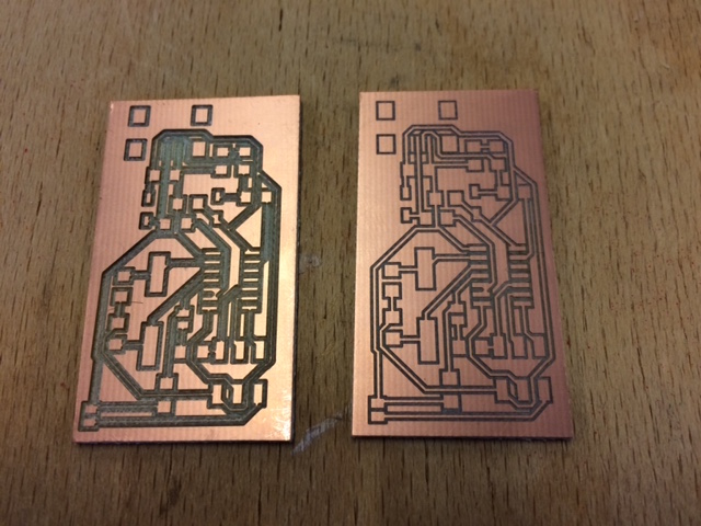
First PCB obtained with by CNC milling with a bad penetration depth (left) and last PCB obtained after a better setting (right).
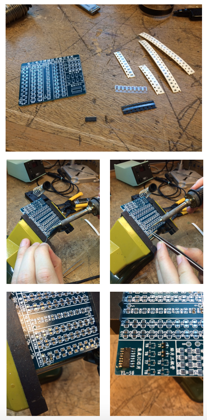
SMD part soldering
The next step will be soldering and testing but for that we need the electronic parts that have not been delivered yet. Meanwhile, I will probably try to practice a little bit SMD part soldering using a kit. The list of parts we should get soon is:
- resistor1 = 1k (labelled 1001)
- resistor2 = 499ohm (labelled 4990)
- resistor3 = 100ohm (labelled 100R)
- resistor4 = 100ohm (labelled 100R)
- resistor5 = 10k (labelled 1002)
- diodezener1 = 3.3v
- diodezener2 = 3.3v
- capacitor1 = 1uf
- capacitor2 = 10pf
- capacitor3 = 10pf
- crystal = 20Mhz
- IC1 = T44 (attiny44ssu)
- j1 = ISP
- j2 = USB
- blank board = fr1 ou (fr4 si c'est plus facile d’accès)
- sj1 = no component (solder-jumper: bridge made of soldering) or 0OHM component
- sj2 = no component (solder-jumper: bridge made of soldering) or 0OHM component
Since we had difficulties getting the parts, we praticed on a the training kit. I could solder the 3 types of resistor 1206, 0805 and 0603, though for the latter I needed the magnifying lens. After that, 0805 caps were easy ! Finally, I soldered SMD transistor and an IC.
Modifying the FabISP board to adjust to the 0402 components baught by our instructor
Unfortunately, our instructor made a mistake when ordering the components from digikeys.
| Quantity | Reference | Reference Fab. | Description | Unit price | Total price |
| 5 | 73-1001- ND | 506 | PCB COPPER CLAD 4X6 1/16" 1-SIDE | 5,43000 | 27,15 € |
| 15 | ATTINY44A- SSU-ND | ATTINY44A-SSU | IC MCU 8BIT 4KB FLASH 14SOIC | 1,19900 | 17,99 € |
| 15 | 644-1039-1- ND | NX5032GA-20.000000MHZ-LN-CD-1 | CRYSTAL 20.0000MHZ 8PF SMD | 0,46300 | 6,95 € |
| 15 | H2961CT- ND | UX60A-MB-5ST | CONN RECEPT MINI USB2.0 5POS | 0,81600 | 12,24 € |
| 15 | 609-3693-1- ND | 20021121-00006C4LF | CONN HEADER 6POS DL UNSHRD SMD | 0,43600 | 6,54 € |
| 50 | 490-6186-1- ND | GRM1555C1H100FA01D | CAP CER 10PF 50V NP0 0402 | 0,02060 | 1,03 € |
| 50 | 490-1320-1- ND | GRM155R60J105KE19D | CAP CER 1UF 6.3V X5R0402 | 0,02620 | 1,31 € |
| 50 | BZT52C3V3- FDICT-ND | BZT52C3V3-7-F | DIODE ZENER 3.3V 500MW SOD123 | 0,16600 | 8,30 € |
| 50 | 311- 1.0KGRCT- ND | RC0603JR-071KL | RES SMD 1K OHM 5% 1/10W 0603 | 0,00720 | 0,36 € |
| 50 | 311- 499LRCT- ND | RC0402FR-07499RL | RES SMD 499 OHM 1% 1/16W 0402 | 0,00840 | 0,42 € |
| 50 | 311- 100LRCT- ND | RC0402FR-07100RL | RES SMD 100 OHM 1% 1/16W 0402 | 0,00840 | 0,42 € |
| 50 | 10KJRCT- ND | RC0402JR-0710KL | RES SMD 10K OHM 5% 1/16W 0402 | 0,00720 | 0,36 € |
| 50 | 311- 0.0GRCT- ND | RC0603JR-070RL | RES SMD 0.0OHM JUMPER 1/10W 0603 | 0,00720 | 0,36 € |
Milling a FabISP with FabModules and MDX40
A little bit later I could use the FabModules and the Roland MDX40 at digiscope to mill a FabISP board.
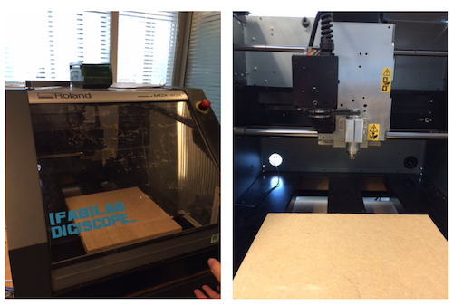
I first installed the 1/64'' (0.4mm) drill that will be used to mill the PCB and fixed the the FR1 laminate (thickness = 1.7 mm) with double sided tape on the MDX40 wood plateau.
I then used the Fab Modules and imported the FabISP.png.
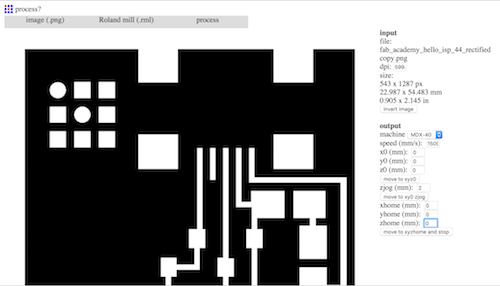
I chose rml in the output format list. I then selected PCB traces 1/64 because I will be using a 1/64'' drill for traces 0.4mm wide. I set 15000 mm/s for the speed. The choice of the 1/64'' sets several parameters to some predefined values (tool diameter = 0.4 mm, cut depth = 0.1 mm, number of offsets = 4 (number of passes), offset overlap = 50%). Finally, I clicked on the 'caclulate' button to ask FabModules to calculate the tool path (black lines, red lines correspond to transport steps of the tool).
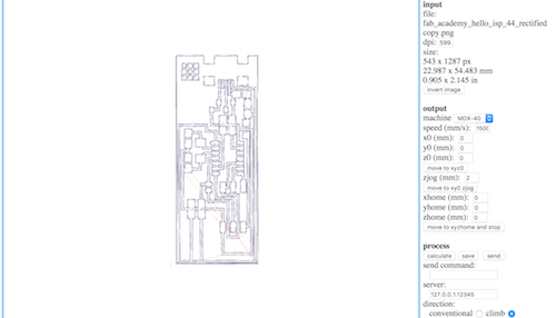
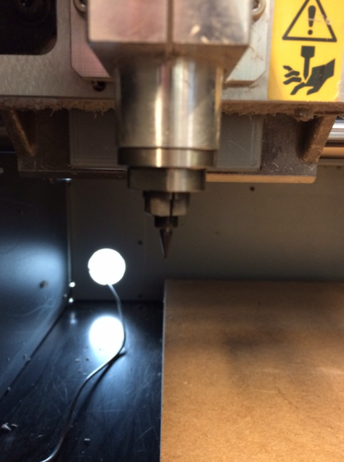
I finished by clicking on the 'save' button to produce a .rml file that I copied on a usb flash drive and plugged the flash drive on the PC so that it could be opened by VPanel the Roland MDX40 software. Before starting the milling, the operator has to set the XYZ origin, the Z origin being the most delicate setting.
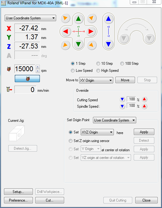
The XYZ origin can be aduster by clicking on the red, green and blue arrows respectively. Different speeds can be used (high, low, 100, 10 and 1 Steps, 1 step is 10 um). I adjusted the drill speed to 15000 rpm but set the cutting speed to 10%. To set the Z origin, I made a slow approch towoard the FR1 laminates with the drill rotating (to avoid breaking the drill in case of strong contact with the laminate). When the tip touches the surface of the FR1 laminate, some chips are clearly visible. I then clicked on the 'Apply' button on the right of Set XYZ Origin. Another technique consist in unmounting the drill (with the rotation turned off) and letting it fall onto the surface of the laminate from a height of 1-2 mm, then will 1 or 2 10um steps, the chips are visible and the Z Origin can be set. Once everyhing is set, the milling process begins by clicking on the 'Cut...' button and selecting the proper .rml file.
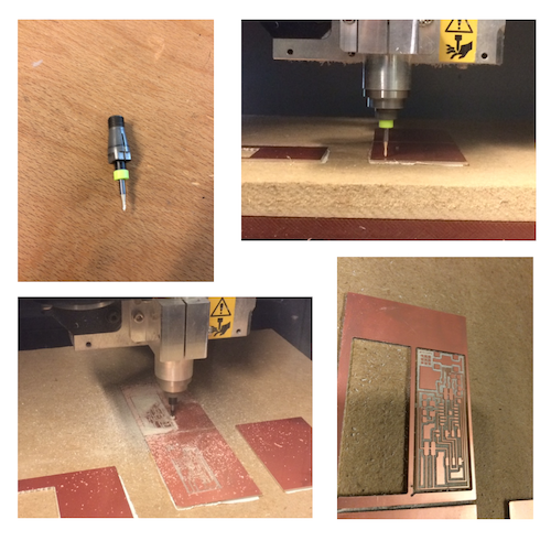
The process is repeated with the 1/32'' drill and the contour .rml file resulting from processing the contour png file with the FabModules (some parameters are changed such as the number of offsets that is set to 1). Once done (Quit cutting) pushing the button 'View' on the MDX40 moves the plateau towards the operator and the board can be removed. Finally, I soldered the SMD components.
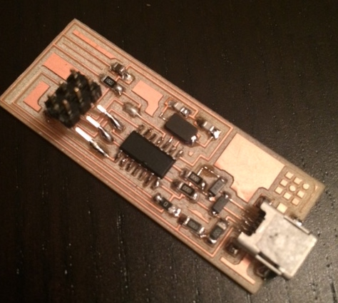
Unfortunately, the programming test did not work. The FabISP is not recognised by the Macbook Pro. Must come back to this later.
Attempts to program the FabISP
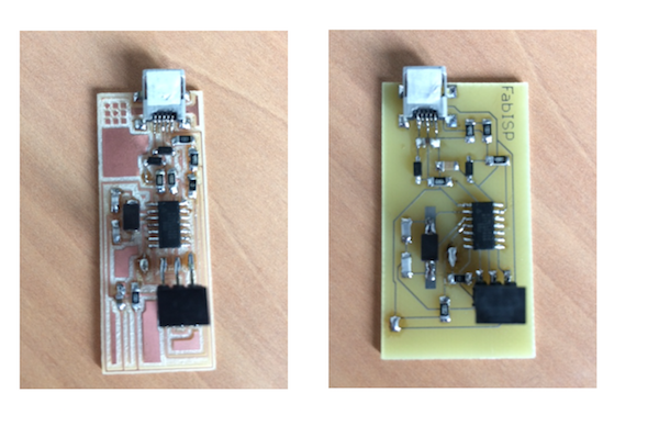
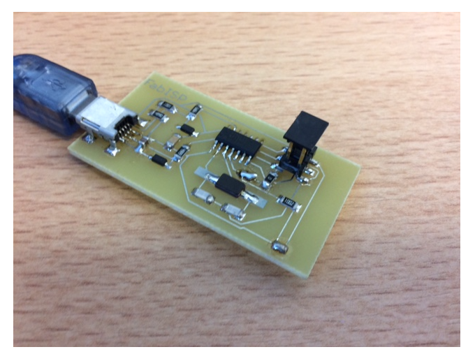
Since the electronic components have finally arrived, I made two FabISPs: one based on Anna Kaziunas' design and one based on David Mellis' design.
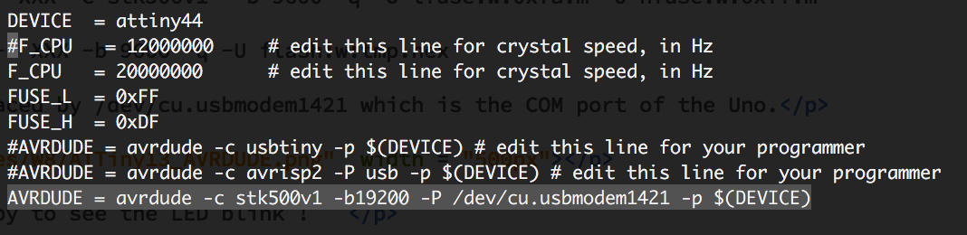
I carefully checked that the boards. No shorts and each pin is connected to what it should be. Since I had no FabISP to program my FabISPs I used an Arduino Uno as an ArduinoISP, pretty much in the same way as described before for the ATTiny13. Except for the Uno as an ISP I followed this tutorial as suggested by my local instructor. I download the firmware, modified the makefile to specify the Arduino Uno as the ISP programmer and add the right /dev/ usb adress for my Uno. Actually, I did it two times, one with an ArduinoISP and one with an AVR ISP that I had.
$Vincents-MacBook-Pro:fabISP_mac.0.8.2_firmware vjmdupuis$ nano Makefile
$Vincents-MacBook-Pro:fabISP_mac.0.8.2_firmware vjmdupuis$ make clean
rm -f main.hex main.lst main.obj main.cof main.list main.map main.eep.hex main.elf *.o usbdrv/*.o main.s usbdrv/oddebug.s usbdrv/usbdrv.s
$Vincents-MacBook-Pro:fabISP_mac.0.8.2_firmware vjmdupuis$ make hex
avr-gcc -Wall -Os -DF_CPU=20000000	 -Iusbdrv -I. -DDEBUG_LEVEL=0 -mmcu=attiny44 -c usbdrv/usbdrv.c -o usbdrv/usbdrv.o
avr-gcc -Wall -Os -DF_CPU=20000000	 -Iusbdrv -I. -DDEBUG_LEVEL=0 -mmcu=attiny44 -x assembler-with-cpp -c usbdrv/usbdrvasm.S -o usbdrv/usbdrvasm.o
avr-gcc -Wall -Os -DF_CPU=20000000	 -Iusbdrv -I. -DDEBUG_LEVEL=0 -mmcu=attiny44 -c usbdrv/oddebug.c -o usbdrv/oddebug.o
avr-gcc -Wall -Os -DF_CPU=20000000	 -Iusbdrv -I. -DDEBUG_LEVEL=0 -mmcu=attiny44 -c main.c -o main.o
main.c:88:13: warning: always_inline function might not be inlinable [-Wattributes]
 static void delay ( void )
             ^
avr-gcc -Wall -Os -DF_CPU=20000000	 -Iusbdrv -I. -DDEBUG_LEVEL=0 -mmcu=attiny44 -o main.elf usbdrv/usbdrv.o usbdrv/usbdrvasm.o usbdrv/oddebug.o main.o
rm -f main.hex main.eep.hex
avr-objcopy -j .text -j .data -O ihex main.elf main.hex
avr-size main.hex
   text	   data	    bss	    dec	    hex	filename
      0	   2002	      0	   2002	    7d2	main.hex

$Vincents-MacBook-Pro:fabISP_mac.0.8.2_firmware vjmdupuis$ make fuse
avrdude -c avrisp2 -P usb -p attiny44  -U hfuse:w:0xDF:m -U lfuse:w:0xFF:m

avrdude: AVR device initialized and ready to accept instructions

Reading | ################################################## | 100% 0.00s

avrdude: Device signature = 0x1e9207
avrdude: reading input file "0xDF"
avrdude: writing hfuse (1 bytes):

Writing | ################################################## | 100% 0.00s

avrdude: 1 bytes of hfuse written
avrdude: verifying hfuse memory against 0xDF:
avrdude: load data hfuse data from input file 0xDF:
avrdude: input file 0xDF contains 1 bytes
avrdude: reading on-chip hfuse data:

Reading | ################################################## | 100% 0.00s

avrdude: verifying ...
avrdude: 1 bytes of hfuse verified
avrdude: reading input file "0xFF"
avrdude: writing lfuse (1 bytes):

Writing | ################################################## | 100% 0.00s

avrdude: 1 bytes of lfuse written
avrdude: verifying lfuse memory against 0xFF:
avrdude: load data lfuse data from input file 0xFF:
avrdude: input file 0xFF contains 1 bytes
avrdude: reading on-chip lfuse data:

Reading | ################################################## | 100% 0.00s

avrdude: verifying ...
avrdude: 1 bytes of lfuse verified

avrdude: safemode: Fuses OK (H:FF, E:DF, L:FF)

avrdude done.  Thank you.

$Vincents-MacBook-Pro:fabISP_mac.0.8.2_firmware vjmdupuis$ make program
avrdude -c avrisp2 -P usb -p attiny44  -U flash:w:main.hex:i

avrdude: AVR device initialized and ready to accept instructions

Reading | ################################################## | 100% 0.00s

avrdude: Device signature = 0x1e9207
avrdude: NOTE: "flash" memory has been specified, an erase cycle will be performed
         To disable this feature, specify the -D option.
avrdude: erasing chip
avrdude: reading input file "main.hex"
avrdude: writing flash (2002 bytes):

Writing | ################################################## | 100% 1.05s

avrdude: 2002 bytes of flash written
avrdude: verifying flash memory against main.hex:
avrdude: load data flash data from input file main.hex:
avrdude: input file main.hex contains 2002 bytes
avrdude: reading on-chip flash data:

Reading | ################################################## | 100% 0.99s

avrdude: verifying ...
avrdude: 2002 bytes of flash verified

avrdude: safemode: Fuses OK (H:FF, E:DF, L:FF)

avrdude done.  Thank you.

avrdude -c avrisp2 -P usb -p attiny44  -U hfuse:w:0xDF:m -U lfuse:w:0xFF:m

avrdude: AVR device initialized and ready to accept instructions

Reading | ################################################## | 100% 0.00s

avrdude: Device signature = 0x1e9207
avrdude: reading input file "0xDF"
avrdude: writing hfuse (1 bytes):

Writing | ################################################## | 100% 0.00s

avrdude: 1 bytes of hfuse written
avrdude: verifying hfuse memory against 0xDF:
avrdude: load data hfuse data from input file 0xDF:
avrdude: input file 0xDF contains 1 bytes
avrdude: reading on-chip hfuse data:

Reading | ################################################## | 100% 0.00s

avrdude: verifying ...
avrdude: 1 bytes of hfuse verified
avrdude: reading input file "0xFF"
avrdude: writing lfuse (1 bytes):

Writing | ################################################## | 100% 0.00s

avrdude: 1 bytes of lfuse written
avrdude: verifying lfuse memory against 0xFF:
avrdude: load data lfuse data from input file 0xFF:
avrdude: input file 0xFF contains 1 bytes
avrdude: reading on-chip lfuse data:

Reading | ################################################## | 100% 0.00s

avrdude: verifying ...
avrdude: 1 bytes of lfuse verified

avrdude: safemode: Fuses OK (H:FF, E:DF, L:FF)

avrdude done.  Thank you.
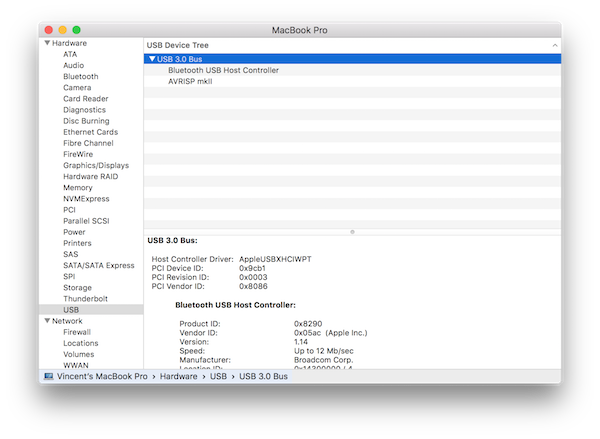
Everything worked execept that after all this, the FabISP is not recognized in the USB list in the Mac System Report. I read that it may be due to USB3. I put a USB2 hub between my Macbook and the FabISP but still the FabISP doesn't show up in the list !!!
Why ? I don't know. I made some resarch in the Student's Archive and ask for advice to my instructor and fellow student but the only answer I got were (maybe a cold joint, try changing a resistor)... that is to say ... I may or may not solder another ISP.
Update after 1st evaluation round
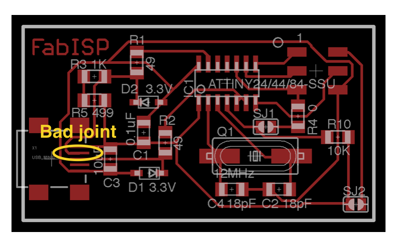
I made many FabISPs and I didn't want to give up. So I came back and reinspected one of my FabISP with a multimeter. I could finally identify a bad solder joint on the USB mini connector. Depending on the way I tested it, the joint was ok or not.
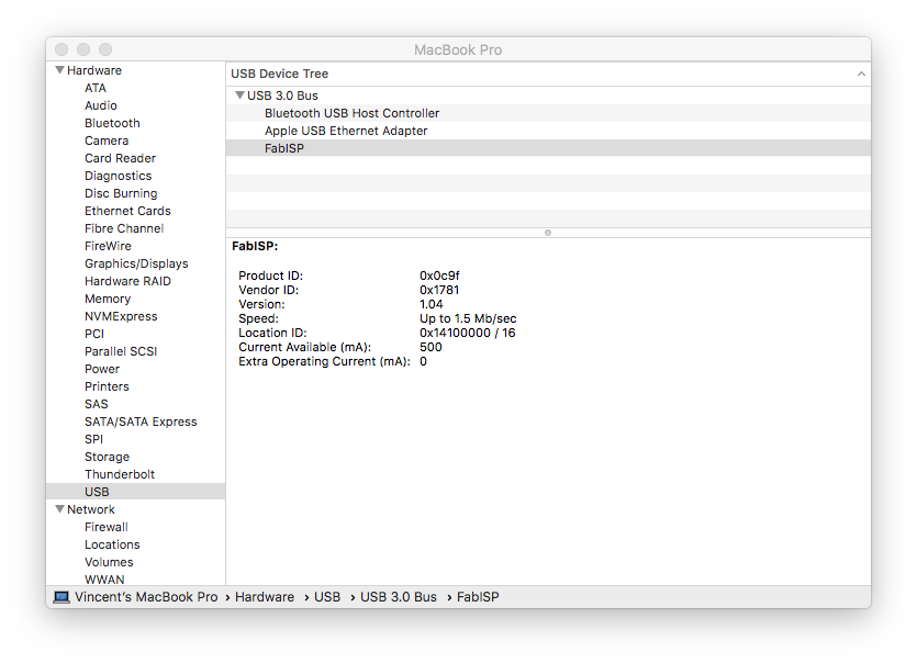
I made a cleaner joint and I was so happy to see the FabISP appear in my Sytem Report in the USB section after plugging the FabISP in my Macbook.
Programming a hello board with the FabISP
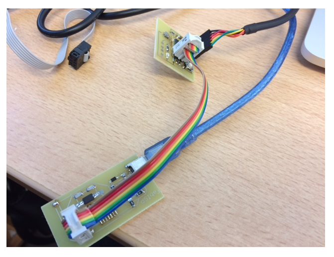
So happy to have a working FabISP (IMPORTANT: I finalized the FabISP by removing the solder joint SJ1), I decided to reprogram my hello board with my FabISP. I used the hello.ftdi.44.echo.c written by Neil. I connected the FabISP and my hello board using the 6 pin ICSP cable and connected the hello board FTDI to my Macbook using a FTDI cable.
I then compiled the c code and flashed the ATTiny44 of the hello board using the following commands in a terminal:
$ make -f hello.ftdi.44.echo.c
$ make -f hello.ftdi.44.echo.c program-usbtiny-fuses
$ make -f hello.ftdi.44.echo.c program-usbtiny
The log is the following
cuivre:6_electronic_design_due_03_09 vjmdupuis$ make -f hello.ftdi.44.echo.c.make
avr-objcopy -O ihex hello.ftdi.44.echo.out hello.ftdi.44.echo.c.hex;\
	avr-size --mcu=attiny44 --format=avr hello.ftdi.44.echo.out
AVR Memory Usage
----------------
Device: attiny44

Program:     758 bytes (18.5% Full)
(.text + .data + .bootloader)

Data:         64 bytes (25.0% Full)
(.data + .bss + .noinit)


cuivre:6_electronic_design_due_03_09 vjmdupuis$ make -f hello.ftdi.44.echo.c.make program-usbtiny-fuses
avr-objcopy -O ihex hello.ftdi.44.echo.out hello.ftdi.44.echo.c.hex;\
	avr-size --mcu=attiny44 --format=avr hello.ftdi.44.echo.out
AVR Memory Usage
----------------
Device: attiny44

Program:     758 bytes (18.5% Full)
(.text + .data + .bootloader)

Data:         64 bytes (25.0% Full)
(.data + .bss + .noinit)


avrdude -p t44 -P usb -c usbtiny -U lfuse:w:0x5E:m

avrdude: AVR device initialized and ready to accept instructions

Reading | ################################################## | 100% 0.00s

avrdude: Device signature = 0x1e9207
avrdude: reading input file "0x5E"
avrdude: writing lfuse (1 bytes):

Writing | ################################################## | 100% 0.01s

avrdude: 1 bytes of lfuse written
avrdude: verifying lfuse memory against 0x5E:
avrdude: load data lfuse data from input file 0x5E:
avrdude: input file 0x5E contains 1 bytes
avrdude: reading on-chip lfuse data:

Reading | ################################################## | 100% 0.00s

avrdude: verifying ...
avrdude: 1 bytes of lfuse verified

avrdude: safemode: Fuses OK (H:FF, E:DF, L:5E)

avrdude done.  Thank you.

cuivre:6_electronic_design_due_03_09 vjmdupuis$ make -f hello.ftdi.44.echo.c.make program-usbtiny
avr-objcopy -O ihex hello.ftdi.44.echo.out hello.ftdi.44.echo.c.hex;\
	avr-size --mcu=attiny44 --format=avr hello.ftdi.44.echo.out
AVR Memory Usage
----------------
Device: attiny44

Program:     758 bytes (18.5% Full)
(.text + .data + .bootloader)

Data:         64 bytes (25.0% Full)
(.data + .bss + .noinit)


avrdude -p t44 -P usb -c usbtiny -U flash:w:hello.ftdi.44.echo.c.hex

avrdude: AVR device initialized and ready to accept instructions

Reading | ################################################## | 100% 0.00s

avrdude: Device signature = 0x1e9207
avrdude: NOTE: "flash" memory has been specified, an erase cycle will be performed
         To disable this feature, specify the -D option.
avrdude: erasing chip
avrdude: reading input file "hello.ftdi.44.echo.c.hex"
avrdude: input file hello.ftdi.44.echo.c.hex auto detected as Intel Hex
avrdude: writing flash (758 bytes):

Writing | ################################################## | 100% 0.58s

avrdude: 758 bytes of flash written
avrdude: verifying flash memory against hello.ftdi.44.echo.c.hex:
avrdude: load data flash data from input file hello.ftdi.44.echo.c.hex:
avrdude: input file hello.ftdi.44.echo.c.hex auto detected as Intel Hex
avrdude: input file hello.ftdi.44.echo.c.hex contains 758 bytes
avrdude: reading on-chip flash data:

Reading | ################################################## | 100% 0.61s

avrdude: verifying ...
avrdude: 758 bytes of flash verified

avrdude: safemode: Fuses OK (H:FF, E:DF, L:5E)

avrdude done.  Thank you.
Finally, I could check with the Serial Monitor of the Arduino IDE that the code was working. By typing character in the Serial Monitor I could see the response of the hello board.
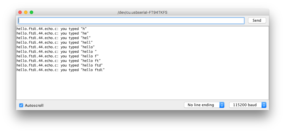
SUCCESS !!!
Finally, although I learned how to use de Modela and how to mill my PCB I made many PCBs using chemical etching because I had the infrastructure available, because the result is very reproducible and because it was a bit complicated for me (due to my teaching agenda in particular) to come to digiscope and train as much as I would have liked on the Modela. Recently though and after the 1st evaluation round we bought a Roland SRM20.
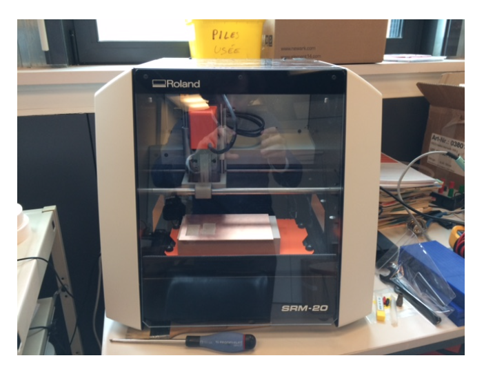
After installing the machine and the software I used the Fabmodules and tried to mill yet another FabISP. The first attempts was bad and I broke the end mill. For the second try, I used a CIF end mill with a conic tip of 30° and an end radius of 0.2 mm. I used 0.4 mm as tool diameter and 0.1 mm depth in the Fabmodule and obtained a pretty good result. I'll probably be using more milling for PCB production using the Fabmodules.