Computer Controlled Cutting
Assignment for this week
- Design, make, and document a press-fit construction kit
- Get familiar with parametric design tools
- Learn how to use the laser cutter and the vinyl cutter
- Use cardboard!
- The press-fit construction kit should make up more than one form
- Link to this week’s home work page
This week lecture was about Computer Controlled Cutting and dealt mainly with vinylcutters and lasercutters. Vinylcutters can be used to cut several types of materials, vinyl of course but also copper films and I would like to try that someday to create soft PCBs. Lasercutters can be used to cardboard, wood and acrylic. They are very fast but need to be supervised due to fire risks. They can be used to cut or to engrave.
This week assignement was the design and making of a press-fit construction kit to build a 3d object from 2d pieces. I looked around and found some documentation in the student archive and on the web. I decided to try to build this
3d from 2d pieces (from Instructables).
and used inkscape for the drawing.
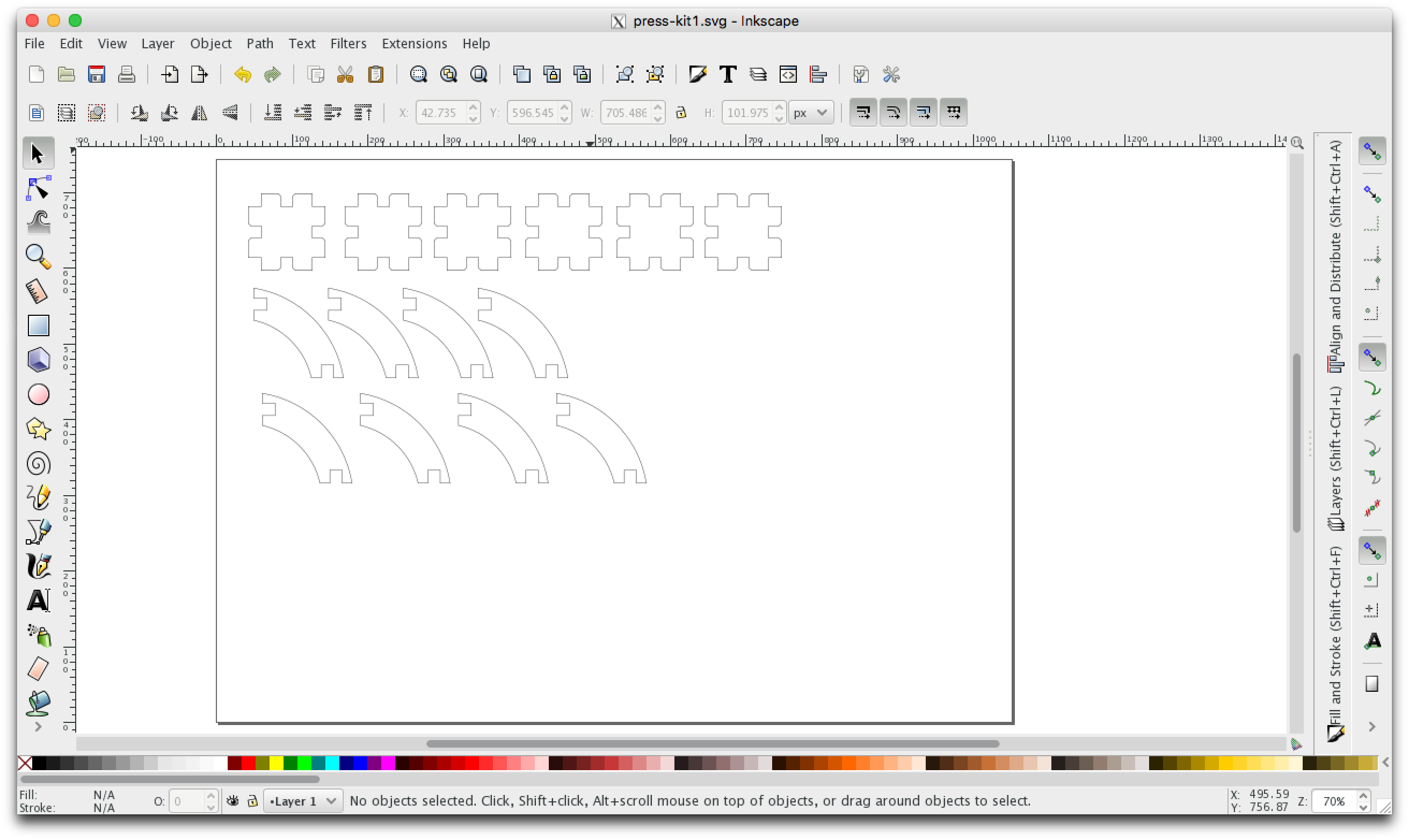
Press-fit construction set using Inkscape.
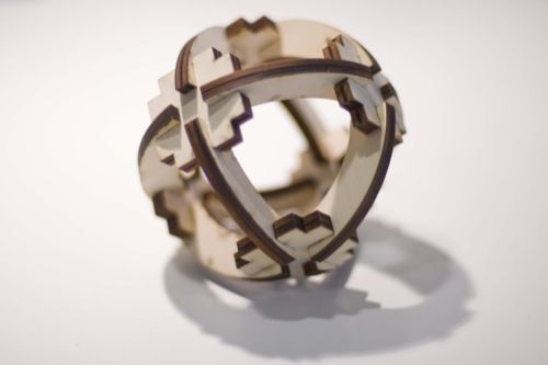
I had to scale a little bit the svg downloaded from instructables to adjust it to the Plywood 3mm that we had in our lab. I also had to used red lines cutting with our Trotec laser printer. The svg file can be found here and the photo of the final object is:
My press-fit 3d globe.
I understand that this was not really parametric design but it is not possible to cut shapes with clones in Inkscape, so I needed more time and other softwares to do real parametric design of press-fit pieces. I used Fusion360 and OpenSCAD and it worked.
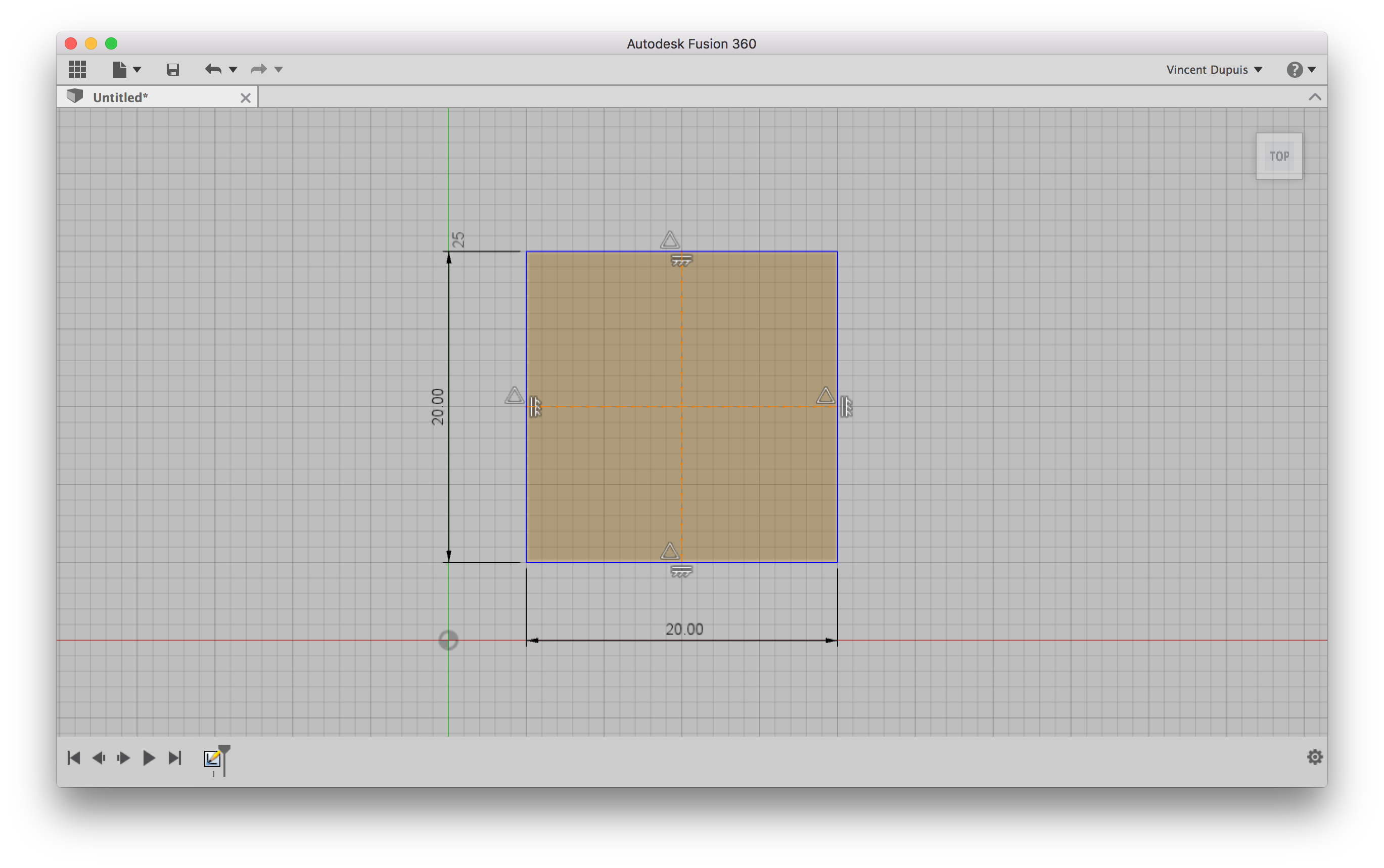
Press-fit parametric design using Fusion360.
I first started with the sketch of a square and added horizontal and vertical dimensions so that it could be resized in a parametric way.
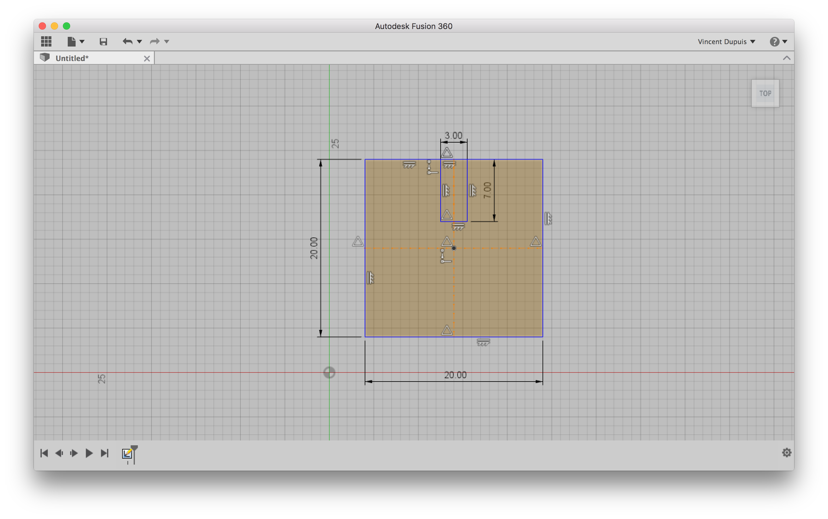
Press-fit parametric design using Fusion360.
I then added another rectangle to serve as a cut, drew two construction lines (horizontal and vertical symetry axes) and added a constraint in to impose the rectangle to be symetrical with respect to the vertical symetry axis.
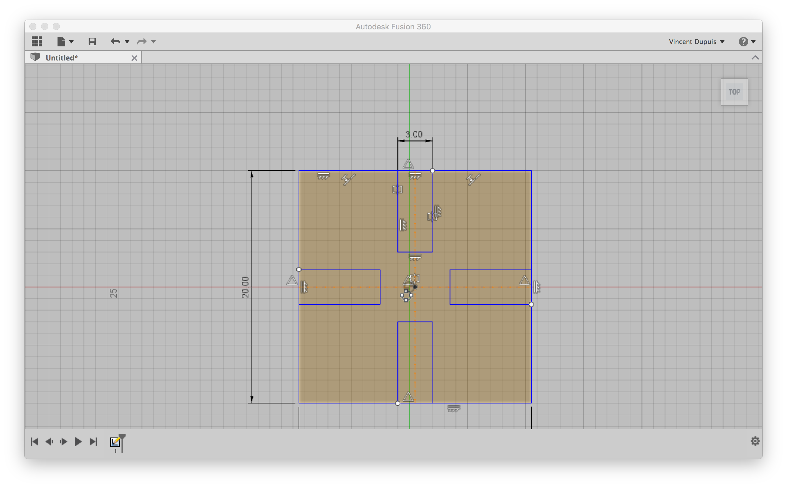
Press-fit parametric design using Fusion360.
I then used the circular pattern functionnality in the sketch dropdown menu to duplicate the cut in a circular pattern choosing 4 elements. At this stage, the sketch can be exported as a .dxf file.
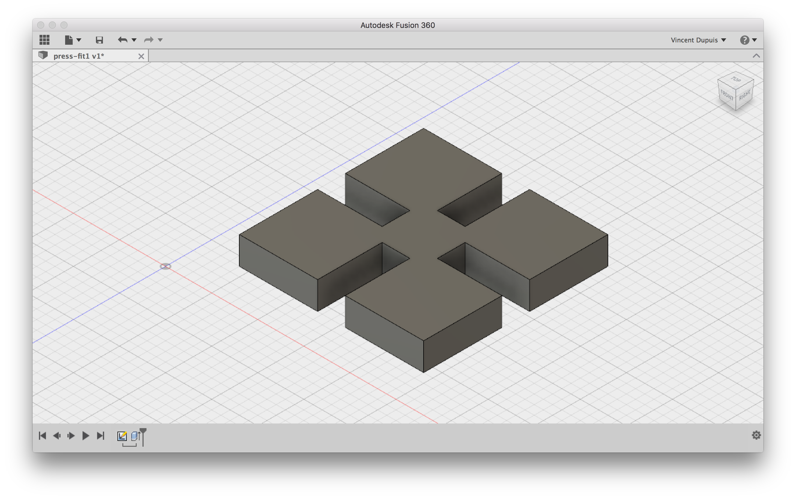
Press-fit parametric design using Fusion360.
Finally, I extruded the sketch in the z direction to create a solid. This solid could be also duplicated and assembled to form a particular 3d object. Finally, as this may be a bit complicated (although necessary for complex designs) I came back to OpenSCAD because as I already mentioned I like the command-line style and it is intrinsically parametric. I a square based press-fit piece and defined 3 parameters (a: length of the side of the square, h and l the lengths of the sides of the rectangular cuts). Here is the code
// press-fit under OpenSCAD
a = 20;
h = 6; l = 3;

module cut (h, l, a) {
    translate([a/2-h/2, 0, 0]) square([h, l], center = true);
}

difference() {
    square([a, a], center = true);
    cut(h, l, a);
    rotate([0,0,90]) cut(h, l, a);
    rotate([0,0,180]) cut(h, l, a);
    rotate([0,0,270]) cut(h, l, a);
}
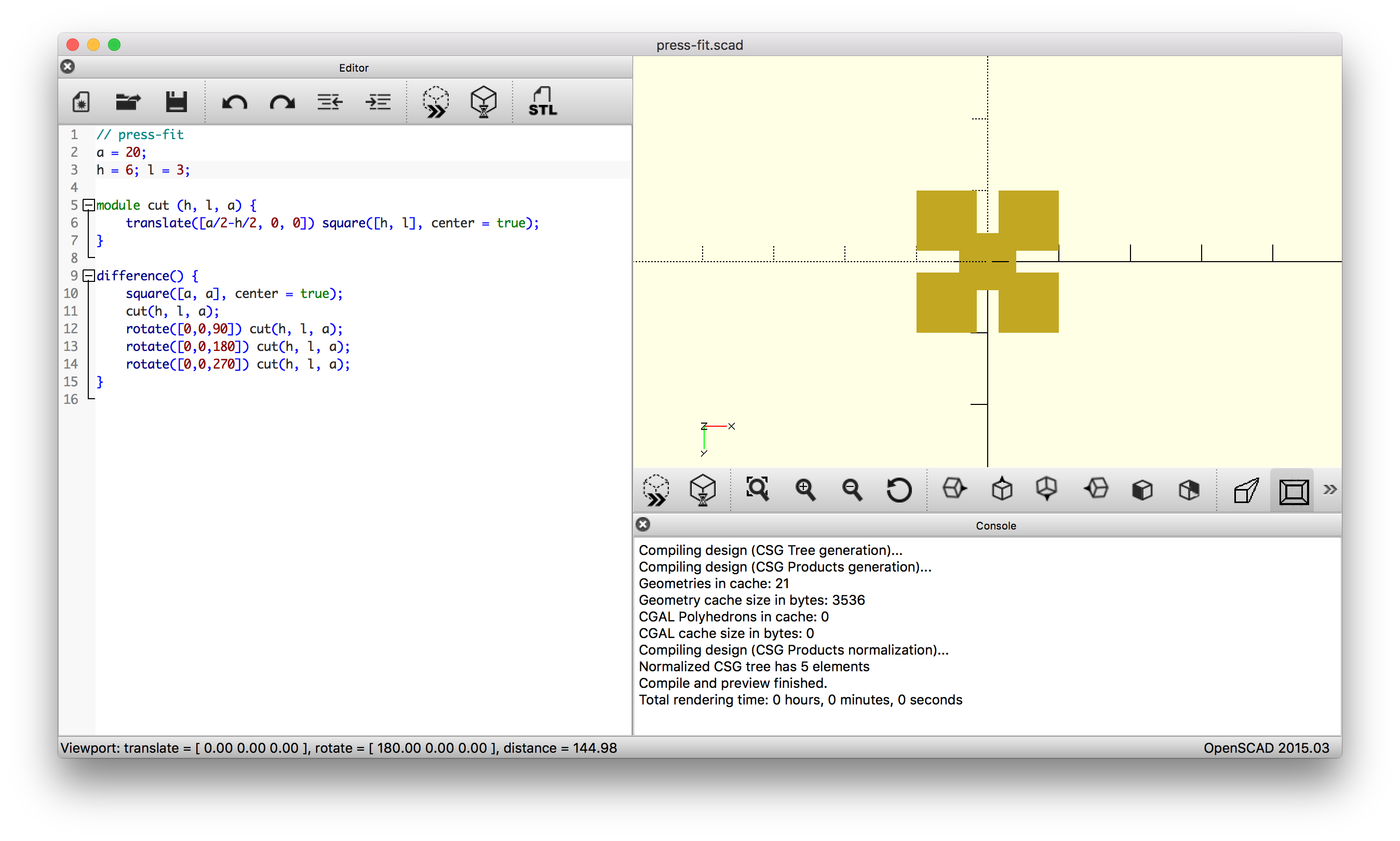
Press-fit parametric design using OpenSCAD.
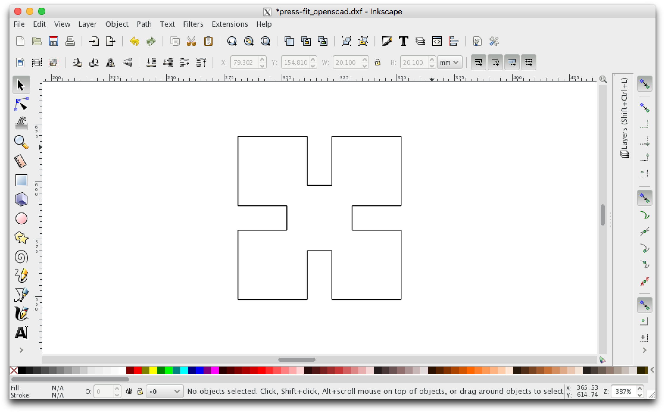
Press-fit parametric design using OpenSCAD exported in dxf and imported in InkScape.
Cutting
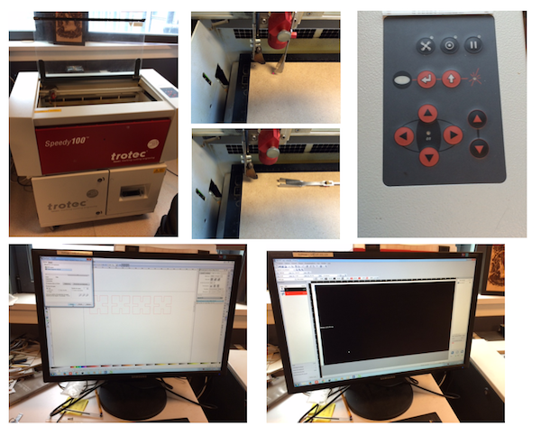
I used 3 mm thick plywood which actually turned out to be 2.7 mm thick when carefully measured. I adjusted the width of the cut in my press-fit design in openscad and repeated the dxf export and was happy to have a parametric design. I used our trotec lasercutter to cut the parts. The software is rather intuitive (it's like a printer) and a list a materials with different cutting parameters corresponding to different thicknesses are already defined (but can be modified). The opertator has neverthess to adjust the focus using a calibrated height piece that fall down on the plywood sheet when one levels the machine bed up.
Here is a picture taken during the cutting process,
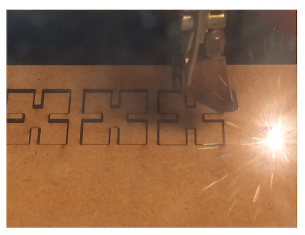
and a video:
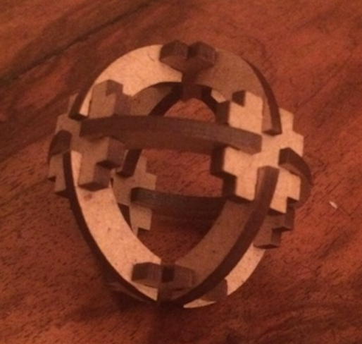
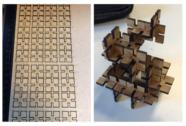
I cutted a few pieces and tested that the assembly was ok with 2.7 mm cuts. Then I repeated the cutting and assembled an object:
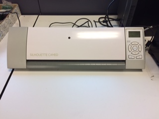
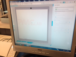
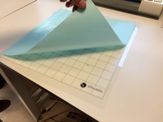
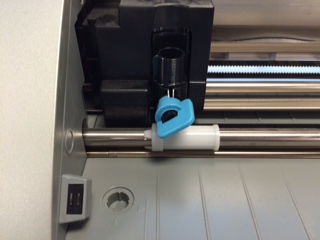
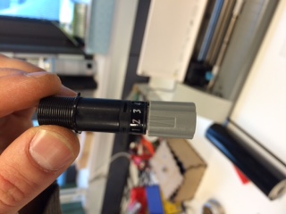
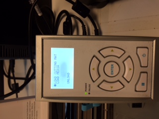
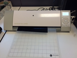
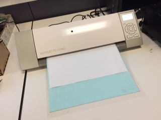
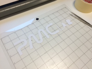
Vynil cutting
Although it was not explicity asked in the assignment, we were encouraged to try to cut something with a vynil cutter. Since we had a Silhouette Cameo in our lab that was not used, we decided to install it and give it a try. In the near future, I want to try to use it for the production of soft PCBs.
 |
 |
 |
 |
 |
 |
 |
 |
 |
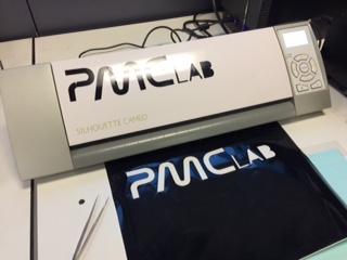 |
First attempts with the Silhouette Cameo vynil cutter.
Cutting the case for my final project
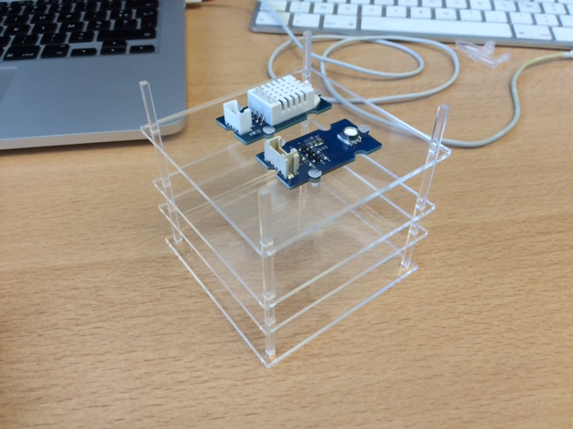
After designing my case for my final project, I used 3 mm thick acrylic and our laser cutter to prepare the case.
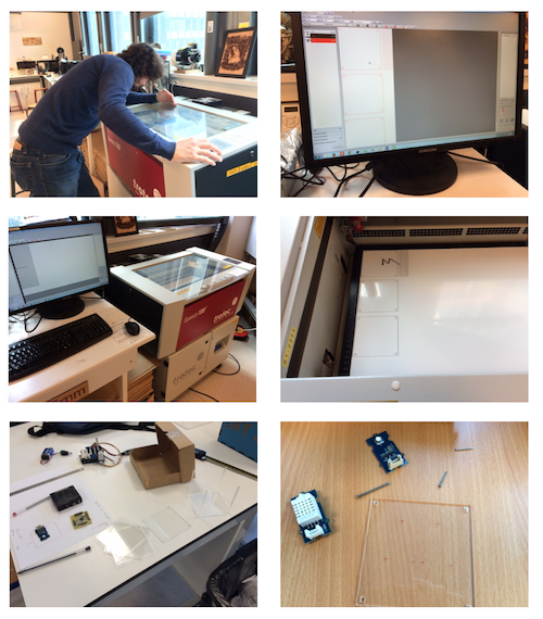
Then I drilled holes and shaped M2 threads in order to screw the sensors.
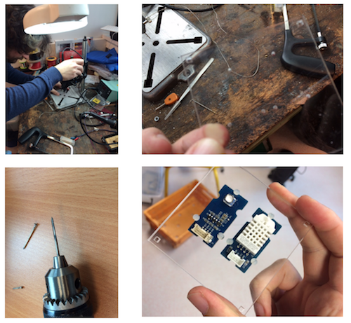
Assembling the parts gave me this: