Input Devices
Assignment for this week
- Measure something: add a sensor to a microcontroller board that you've designed and read it.
- Link to this week´s homeworks page.
This page is organized as follows:
Measuring a distance
The sensor
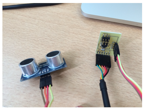
For this week's assignment, I decided to redesign the Hello.HC-SR04 board that uses a HC-SR04 sensor based on ultrasonic transducers (emitter/receiver) to mesure a distance. The sensor datasheet provides the necessary information on how to use the sensor.

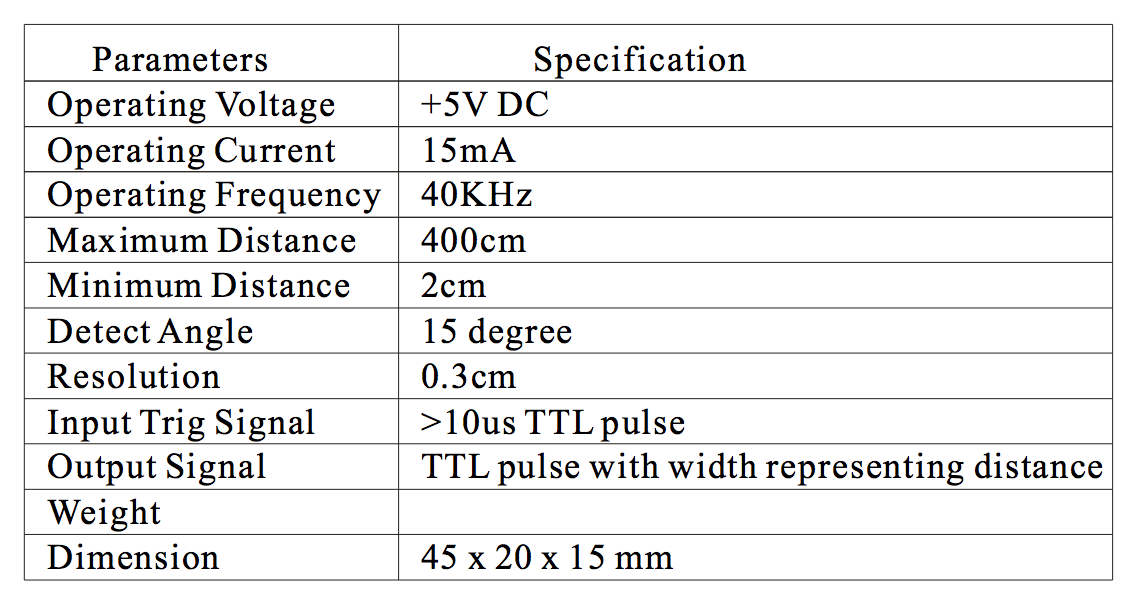
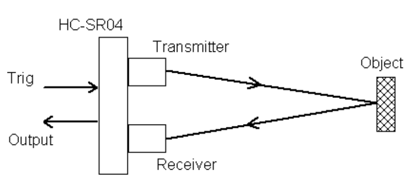
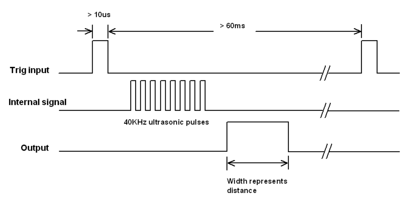
The sensor has 4 pins (the supply pins Vcc and GND, and 2 signal pins trig). When properly operated and trigged (by applying a 10 us pulse on the trig pin), the HC-SR04 generates 40 kHz ultrasonic pulses and listens to echos reflected by a distant object. From these echos, the sensor generates a pulse on the echo pin whose width is the total traveling time of the ultrasonic wave. The distance between the sensor and the object can then be calculated from this traveling time by multiplying by the sound velocity (340 m/s) and dividing by 2.
Niel's board
The Sonar board example presented during the class that uses the HC-SR04 sensor is the following:
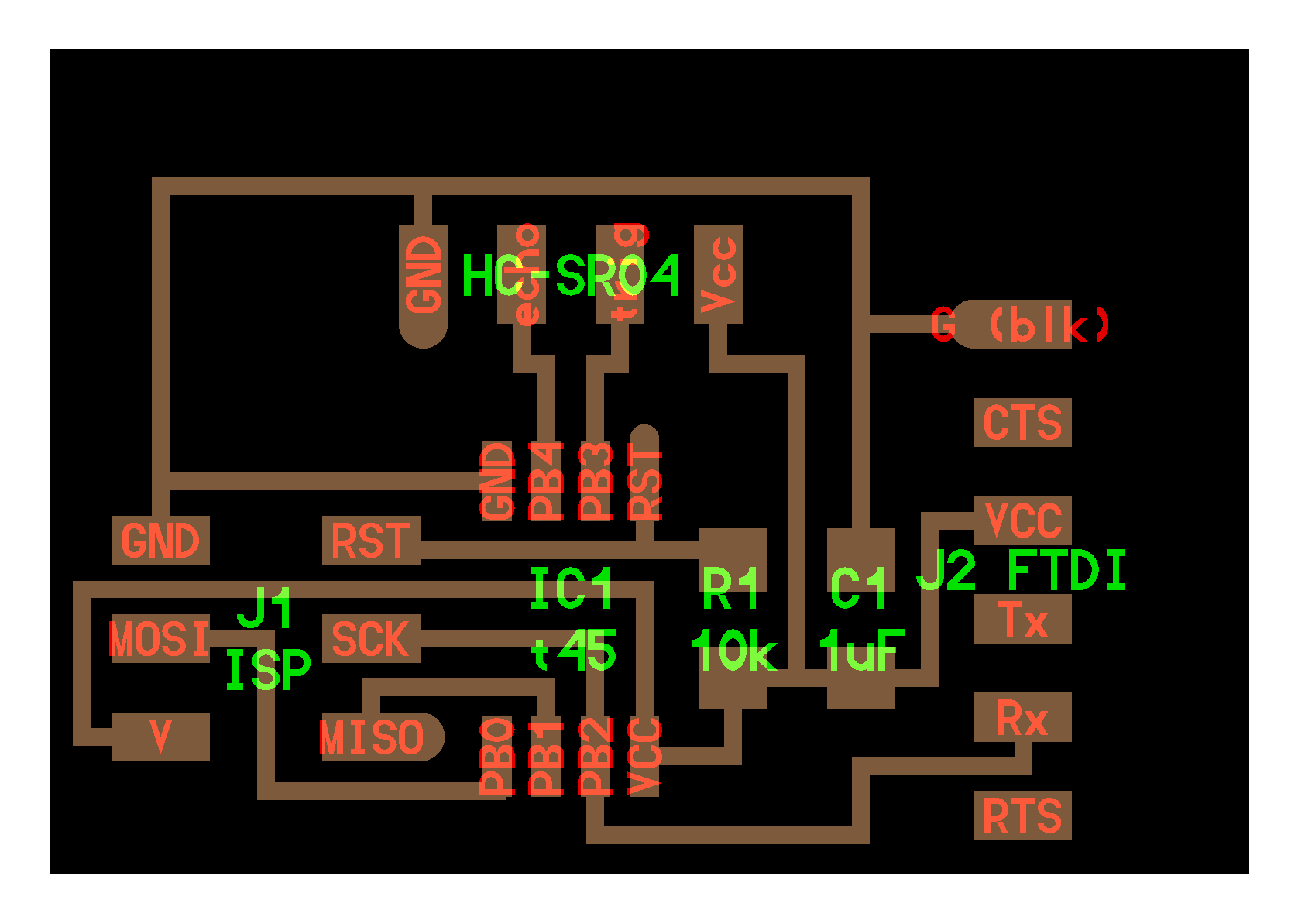
It is based on a ATTiny45 microcontroller and includes a 6 pin header (on the left of the figure) for ISP programming as well as 6 pin FTDI header (on the right) for serial RX/TX communication. As usual, a 10k resistor between the Reset pin and the VCC and an 1 uF capacitor for decoupling the power supply. A 4 pin header (GND, echo, trig, Vcc) with echo and trig being connected to pins PB4 and PB4 on the t45 is used to connect the board and the sensor.
I etched the board and soldered the components.
My board
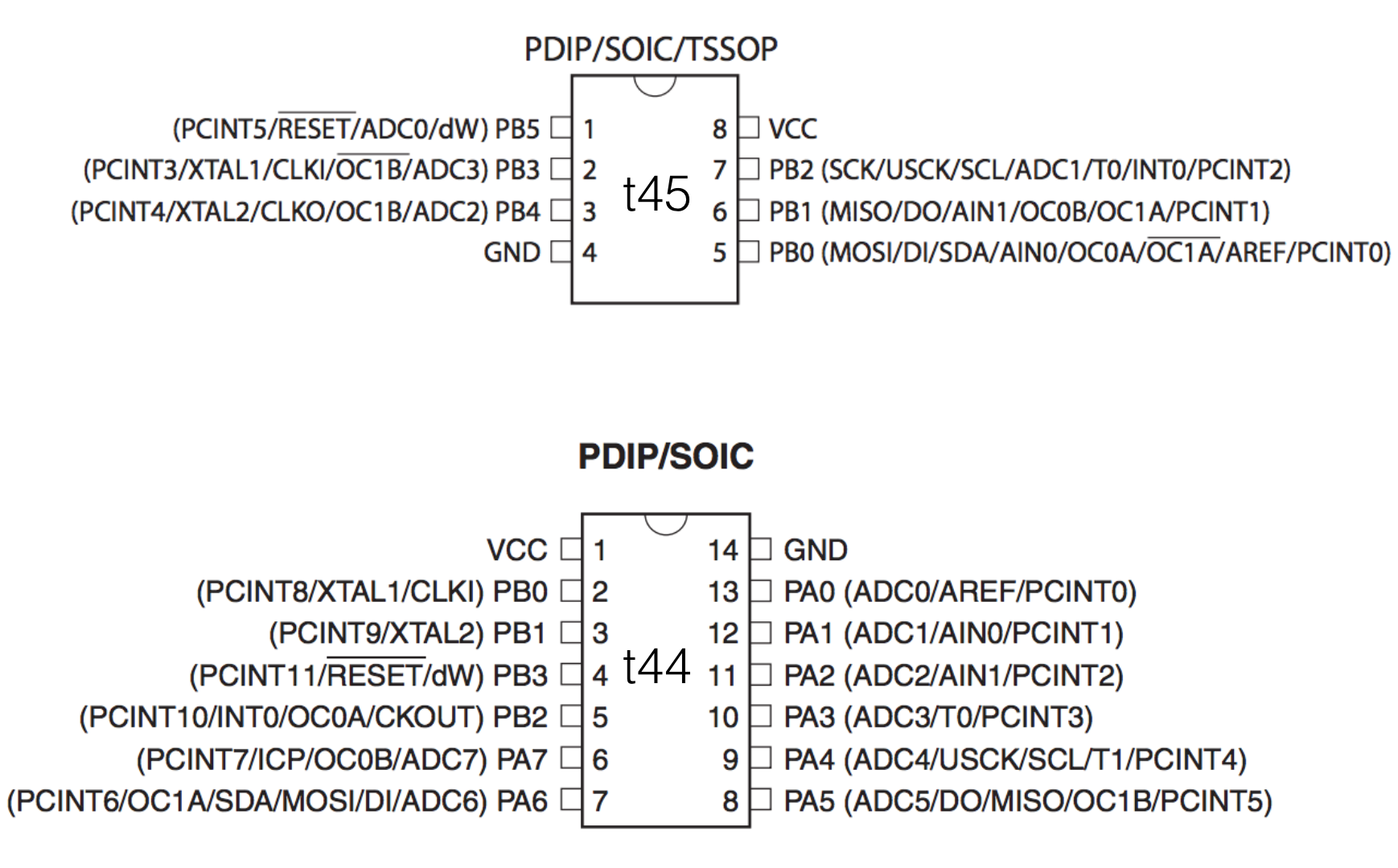
Since the assignment consisted in redesigning a board that would integrate an input device, make it and read it, I decided to switch from the ATTiny45 with its 8 pins (with only 2 availables for input/output) to ATTiny44 that has 14 pins.
I used Eagle.
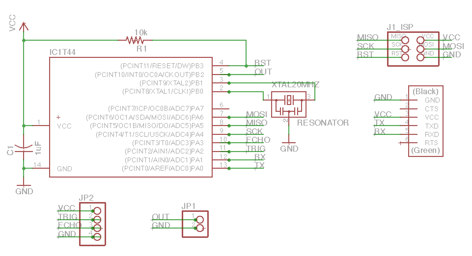
I have a t44 with a 20 MHz crystal and the ISP and FTDI connectors and I added a 4 pin connector JP2 for the sensor (trig and echo are connected to PA2 and PA3 on the t44. I also added a 2 pin connector JP2 (connected to PA5 and GND) to allow for output such as a LED for instance. PA6 remains available and is not used in this design.
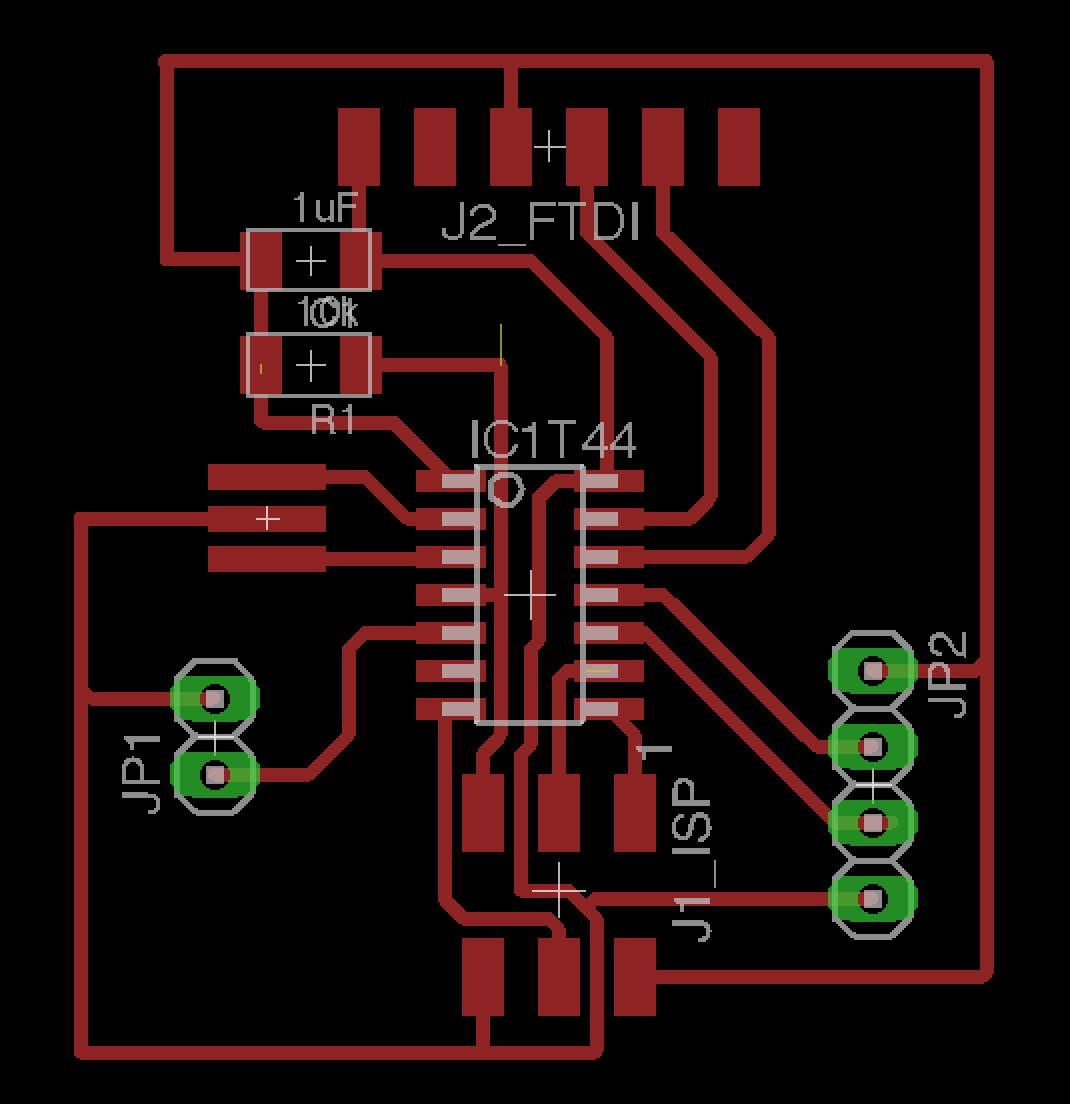
For the PCB layout, I wanted the ISP and FTDI headers to be on two opposite sides of the board. I thus adapted the basic Hello board from the Electonics Design assignment. I used chemical etching to make the board, soldered the different parts and then checked every solder joint with a DMM (one needle tip on the trace, the other on the part). This last step is absolutely critical as bad joints are frequent.
ISP programming
I looked at the (hello.HC-SR04.c, hello.HC-SR04.make) and the (hello.ftdi.44.echo.c, hello.ftdi.44.echo.c.make) codes. The idea was to adapt the code given for the t45 to the t44. The makefile for the t45 is starting with
PROJECT=hello.HC-SR04
SOURCES=$(PROJECT).c
MMCU=attiny45
F_CPU = 8000000

CFLAGS=-mmcu=$(MMCU) -Wall -Os -DF_CPU=$(F_CPU)

$(PROJECT).hex: $(PROJECT).out
	avr-objcopy -O ihex $(PROJECT).out $(PROJECT).c.hex;\
	avr-size --mcu=$(MMCU) --format=avr $(PROJECT).out

$(PROJECT).out: $(SOURCES)
	avr-gcc $(CFLAGS) -I./ -o $(PROJECT).out $(SOURCES)
...
I replaced MMCU=attiny45 by MMCU=attiny44 and changed F_CPU to 20000000. The rest of the code is composed of the avrdude commands for the different programmers. For usbtiny,
program-usbtiny: $(PROJECT).hex
	avrdude -p t45 -P usb -c usbtiny -U flash:w:$(PROJECT).c.hex
Looking at the makefile for the t44, I noticed two lines instead of one for the avrdude call.
program-usbtiny: $(PROJECT).hex
	avrdude -p t44 -P usb -c usbtiny -U flash:w:$(PROJECT).c.hex

program-usbtiny-fuses: $(PROJECT).hex
	avrdude -p t44 -P usb -c usbtiny -U lfuse:w:0x5E:m
So I added those lines. Then the main hello.HC-SR04.c code consist of three main parts. One finds definitions at the beginning (#define directives), then a put_char(volatile unsigned char *port, unsigned char pin, char txchar) function (to serial send a character txchar) and the main function contain the main commands to interact with the sensor and send character on the serial port. The hello.ftdi.44.echo.c has the same structure. In addition to the put_char function, a get_char and a put_string functions are also implemented. The main function in this case reads from serial and then send back the string read to serial.
I replace all the references to PORTB in the t45 by PORTA for the t44. To ISP program the t44 I used the command
make -f hello44.HC-SR04.c.make program-usbtinyAnd .... I had this error.
pc27:hello_HC-SR04 vjmdupuis$ make -f hello44.HC-SR04.c.make program-usbtiny
avr-gcc -mmcu=attiny44 -Wall -Os -DF_CPU=20000000 -I./ -o hello44.HC-SR04.out hello44.HC-SR04.c
hello44.HC-SR04.c: In function 'main':
hello44.HC-SR04.c:144:7: error: 'TIFR' undeclared (first use in this function)
       TIFR |= (1 << TOV0);
       ^
hello44.HC-SR04.c:144:7: note: each undeclared identifier is reported only once for each function it appears in
make: *** [hello44.HC-SR04.out] Error 1
Debugging
What to do when you get this kind of error ? Well you tried to google the error and you spent a lot of time searching forums, ... In the end I said to myself, ok let's learn more deeply how timers work on AVR. I can recommend these links 1 and 2. The code in the main function is the following:
// start counter
   //
   TCCR0B |= (1 << CS00); // prescale /1
   //
   // main loop
   //
   while (1) {
      //
      // trigger pulse
      //
      set(trigger_port,trigger_pin);
      _delay_us(10);
      clear(trigger_port,trigger_pin);
      //
      // wait for echo rising edge
      //
      high = 0;
      TCNT0 = 0;
      TIFR |= (1 << TOV0);
      while (1) {
         if ((echo_pins & echo_pin) != 0) // check for rising edge
            break;
         if ((TIFR & (1 << TOV0)) != 0) { // check for counter overflow
            high += 1;
            if (high == timeout)
               break;
            TIFR |= (1 << TOV0);
            }
         }
      //
I decided to get a deeper understanding of the Niel's code. I learned that TCCR0B is the Timer Counter Control Register and is used to configure the timer. CS00 is the first bit of this 8 bit register and actually it is possible to set the frequency of the timer by 8, 64, 256 by choosing the value of the first 3 bits CS00, CS01 and CS02. In our case 001 means no division which is consistent with Neil's comment. Then comes TCNT0. This is the Timer Counter register that contains the value of the counter. In the code it is resetted to 0. The comes TIFR is the Timer/Counter Interrupt Flag Register whose first bit TOV0 is set to 1 when the timer overflows.
Since it is related to interruptions and that the error message just means that avr gcc just does not know what TIFR is, and following code examples on the internet I tried to add a #include < avr/interrupt.h > which should do no harm. Nope. In the end I just tried to replace TIFR by TIFR0 and ... the error went out. I could check with the terminal that the board was firing data on the Serial port. The hello.HC-SR04.py script gives something but not exactly what Niel observed in his video.
Measuring a temperature
The temperature board example presented during the class that uses a NTC temperature sensor mounted in a bridge configuration with three 10k resistors to increase the sensitivity. As usual, the 6 pin connector for ISP programming on the left and the FDTI connector on the right for serial communication.

I etched the board and soldered the different components. The board before and after soldering is shown below.
To program the board I used my USBTiny programmer and the 6 pin ISP connector. I used the makefile provided on the class page, plugged my USBTiny programmer on the 6 pin ISP header and flashed the board using
make -f hello.temp.45.make programm-usbtinyThe c code provided by Neil is the following. It consists in the serial put_char function followed by the main function that configures the ADC with PB3 and PB4 as input pins and send the data (2 bytes H and L) preceeded by a 1,2,3,4 framing sequence.
//
//
// hello.temp.45.c
//
// thermistor hello-world
//    9600 baud FTDI interface
//
// Neil Gershenfeld
// 10/27/10
//
// (c) Massachusetts Institute of Technology 2010
// This work may be reproduced, modified, distributed,
// performed, and displayed for any purpose. Copyright is
// retained and must be preserved. The work is provided
// as is; no warranty is provided, and users accept all
// liability.
//

#include
#include

#define output(directions,pin) (directions |= pin) // set port direction for output
#define set(port,pin) (port |= pin) // set port pin
#define clear(port,pin) (port &= (~pin)) // clear port pin
#define pin_test(pins,pin) (pins & pin) // test for port pin
#define bit_test(byte,bit) (byte & (1 << bit)) // test for bit set
#define bit_delay_time 102 // bit delay for 9600 with overhead
#define bit_delay() _delay_us(bit_delay_time) // RS232 bit delay
#define half_bit_delay() _delay_us(bit_delay_time/2) // RS232 half bit delay
#define char_delay() _delay_ms(10) // char delay

#define serial_port PORTB
#define serial_direction DDRB
#define serial_pin_out (1 << PB2)

void put_char(volatile unsigned char *port, unsigned char pin, char txchar) {
   //
   // send character in txchar on port pin
   //    assumes line driver (inverts bits)
   //
   // start bit
   //
   clear(*port,pin);
   bit_delay();
   //
   // unrolled loop to write data bits
   //
   if bit_test(txchar,0)
      set(*port,pin);
   else
      clear(*port,pin);
   bit_delay();
   if bit_test(txchar,1)
      set(*port,pin);
   else
      clear(*port,pin);
   bit_delay();
   if bit_test(txchar,2)
      set(*port,pin);
   else
      clear(*port,pin);
   bit_delay();
   if bit_test(txchar,3)
      set(*port,pin);
   else
      clear(*port,pin);
   bit_delay();
   if bit_test(txchar,4)
      set(*port,pin);
   else
      clear(*port,pin);
   bit_delay();
   if bit_test(txchar,5)
      set(*port,pin);
   else
      clear(*port,pin);
   bit_delay();
   if bit_test(txchar,6)
      set(*port,pin);
   else
      clear(*port,pin);
   bit_delay();
   if bit_test(txchar,7)
      set(*port,pin);
   else
      clear(*port,pin);
   bit_delay();
   //
   // stop bit
   //
   set(*port,pin);
   bit_delay();
   //
   // char delay
   //
   bit_delay();
   }

int main(void) {
   //
   // main
   //
   static char chr;
   //
   // set clock divider to /1
   //
   CLKPR = (1 << CLKPCE);
   CLKPR = (0 << CLKPS3) | (0 << CLKPS2) | (0 << CLKPS1) | (0 << CLKPS0);
   //
   // initialize output pins
   //
   set(serial_port, serial_pin_out);
   output(serial_direction, serial_pin_out);
   //
   // init A/D
   //
   ADMUX = (0 << REFS2) | (0 << REFS1) | (0 << REFS0) // VCC ref
      | (0 << ADLAR) // right adjust
      | (0 << MUX3) | (1 << MUX2) | (1 << MUX1) | (1 << MUX0); // 20(PB4-PB3)
   ADCSRA = (1 << ADEN) // enable
      | (1 << ADPS2) | (1 << ADPS1) | (1 << ADPS0); // prescaler /128
   ADCSRB = (1 << BIN); // bipolar mode
   //
   // main loop
   //
   while (1) {
      //
      // send framing
      //
      put_char(&serial_port, serial_pin_out, 1);
      char_delay();
      put_char(&serial_port, serial_pin_out, 2);
      char_delay();
      put_char(&serial_port, serial_pin_out, 3);
      char_delay();
      put_char(&serial_port, serial_pin_out, 4);
      char_delay();
      //
      // initiate conversion
      //
      ADCSRA |= (1 << ADSC);
      //
      // wait for completion
      //
      while (ADCSRA & (1 << ADSC))
         ;
      //
      // send result
      //
      chr = ADCL;
      put_char(&serial_port, serial_pin_out, chr);
      char_delay();
      chr = ADCH;
      put_char(&serial_port, serial_pin_out, chr);
      char_delay();
      }
   }
The python script provided by Neil is the following:
#
# hello.temp.45.py
#
# receive and display temperature
# hello.temp.45.py serial_port
#
# Neil Gershenfeld
# CBA MIT 3/27/12
#
# (c) Massachusetts Institute of Technology 2012
# Permission granted for experimental and personal use;
# license for commercial sale available from MIT
#

from Tkinter import *
from numpy import log
import serial

WINDOW = 600 # window size
eps = 0.5 # filter time constant
filter = 0.0 # filtered value

def idle(parent,canvas):
   global filter, eps
   #
   # idle routine
   #
   byte2 = 0
   byte3 = 0
   byte4 = 0
   ser.flush()
   while 1:
      #
      # find framing
      #
      byte1 = byte2
      byte2 = byte3
      byte3 = byte4
      byte4 = ord(ser.read())
      if ((byte1 == 1) & (byte2 == 2) & (byte3 == 3) & (byte4 == 4)):
         break
   low = ord(ser.read())
   high = ord(ser.read())
   value = 256*high + low
   if (value > 511):
      value -= 1024
   V = 2.5 - value*5.0/(20.0*512.0)
   R = 10000.0/(5.0/V-1.0)
   # NHQ103B375R5
   # R25 10000 (O)
   # B (25/85) 3750 (K)
   # R(T(C)) = R(25)*exp(B*(1/(T(C)+273.15)-(1/(25+273.15))))
   B = 3750.0
   R25 =  10000.0
   T = 1.0/(log(R/R25)/B+(1/(25.0+273.15))) - 273.15
   filter = (1-eps)*filter + eps*T
   x = int(.2*WINDOW + (.9-.2)*WINDOW*(filter-20.0)/10.0)
   canvas.itemconfigure("text",text="%.2f"%filter)
   canvas.coords('rect1',.2*WINDOW,.05*WINDOW,x,.2*WINDOW)
   canvas.coords('rect2',x,.05*WINDOW,.9*WINDOW,.2*WINDOW)
   canvas.update()
   parent.after_idle(idle,parent,canvas)

#
#  check command line arguments
#
if (len(sys.argv) != 2):
   print "command line: hello.temp.45.py serial_port"
   sys.exit()
port = sys.argv[1]
#
# open serial port
#
ser = serial.Serial(port,9600)
ser.setDTR()
#
# start plotting
#
root = Tk()
root.title('hello.temp.45.py (q to exit)')
root.bind('q','exit')
canvas = Canvas(root, width=WINDOW, height=.25*WINDOW, background='white')
canvas.create_text(.1*WINDOW,.125*WINDOW,text=".33",font=("Helvetica", 24),tags="text",fill="#0000b0")
canvas.create_rectangle(.2*WINDOW,.05*WINDOW,.3*WINDOW,.2*WINDOW, tags='rect1', fill='#b00000')
canvas.create_rectangle(.3*WINDOW,.05*WINDOW,.9*WINDOW,.2*WINDOW, tags='rect2', fill='#0000b0')
canvas.pack()
root.after(100,idle,root,canvas)
root.mainloop()
Connecting the FTDI cable and invoking the python script. I could check that the board was properly working.
Update after first evaluation
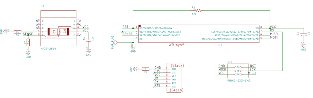
After 1st evaluation round, I was asked by the reviewer to make a MC input board and provide the design files and firmware code. I decided to design and make a board that integrates an ozone sensor MICS2614.
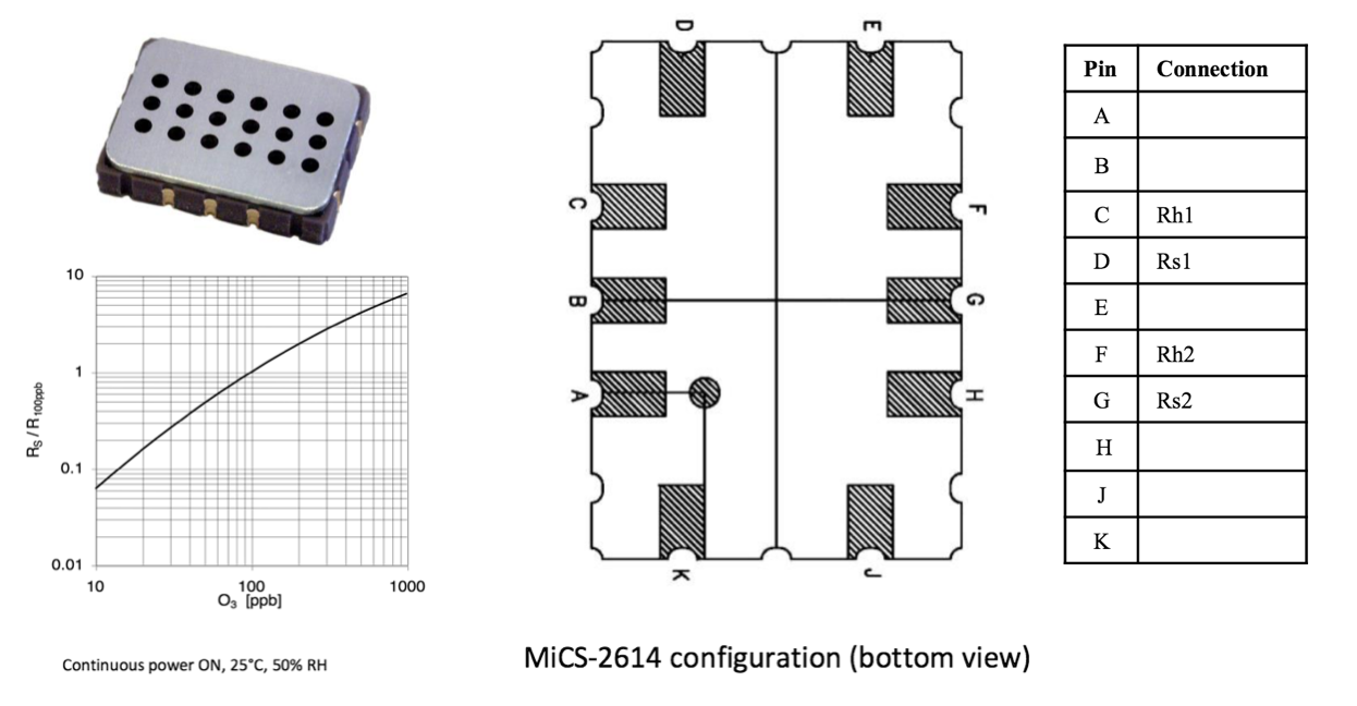
The sensor behaves as a resistor whose resistance value increases with the ozone concentration. It also includes a heater that needs to be fed with an appropriate current. The supply circuit and measurement circuits are as follows:
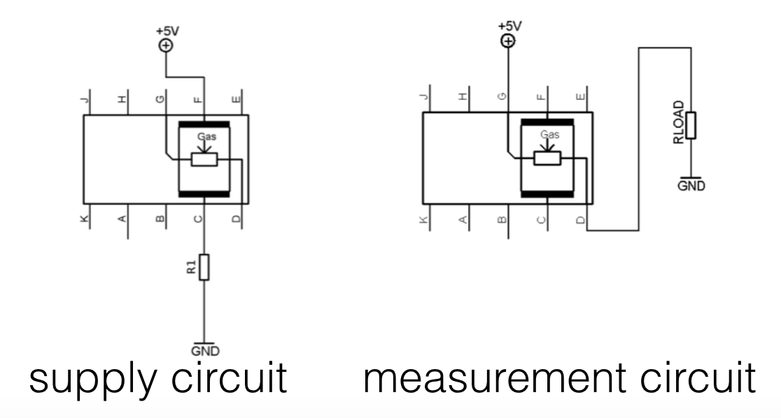
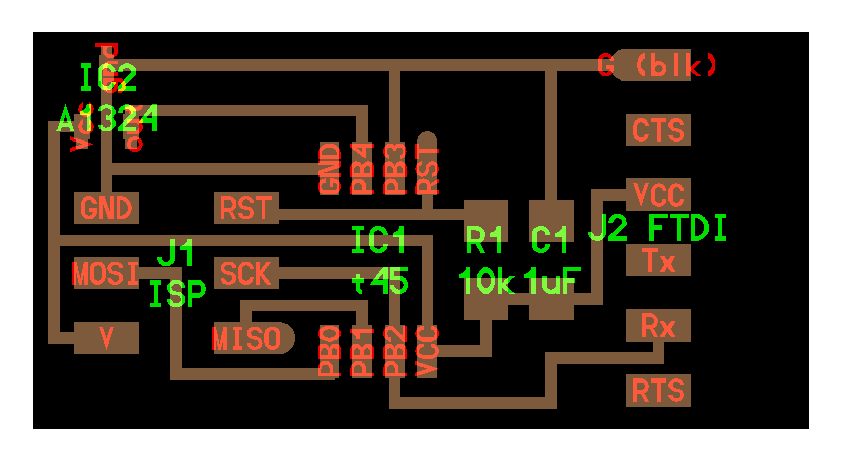
The idea is to associate the MICS2614 with a load resistance, measure the voltage across the load (using a microcontraller ADC) and deduce the value of sensor's resistance and then the ozone concentration. I used Kicad to design my board. The schematics is inspired from the hello.mag.45 board seen in class. The voltage across the load (which I named SENSE) is fed to the PB4 pin of an ATTiny85 microcontroller.
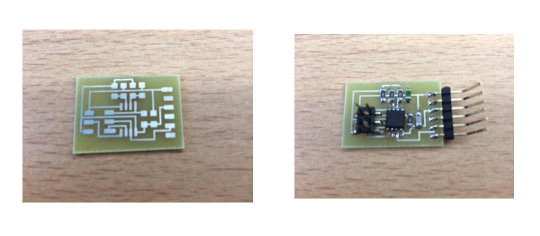
The board layout is shown below. I included a ground (GND) plane.
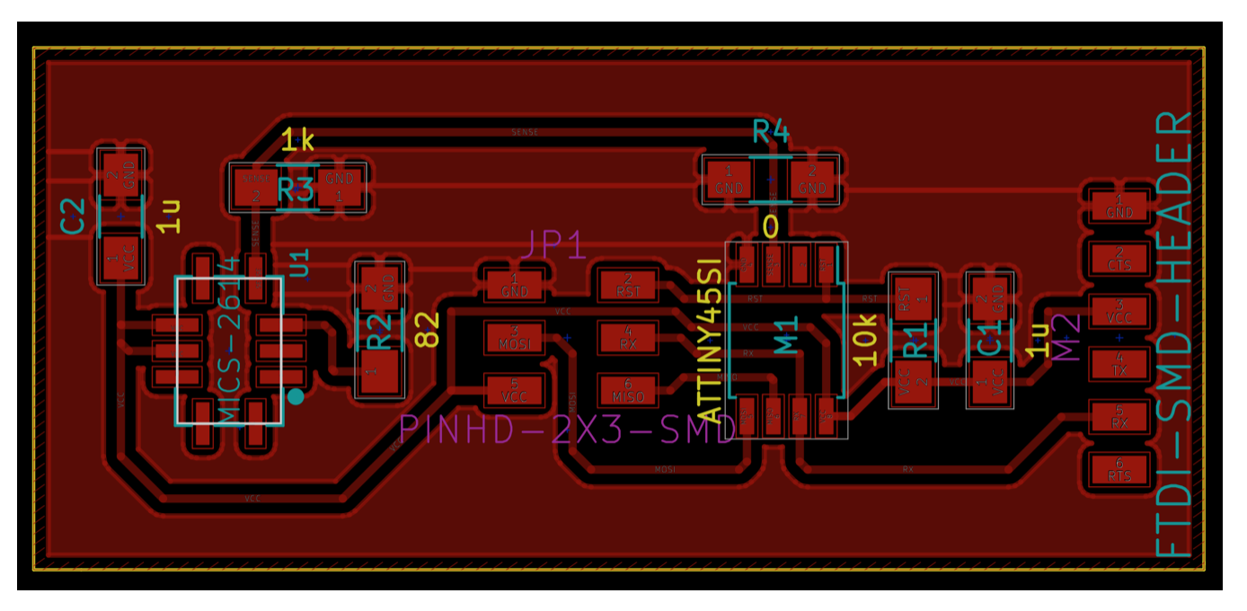
I etched the board and soldered the different electronic components. I checked all the joints and everything was ok.

I then turned to programming. Again, I looked at the code written by Neil for the hello.mag.45 example. This code uses PB2 for serial out and accumulate nsamples = 100 readings on ADC4 before sending the sum on serial with a 1 2 3 4 framing.
//
// hello.mics.85.c
// adapted from hello.mag.45.c
//
// Hall effect magnetic sensing hello-world
//    9600 baud FTDI interface
//
// Neil Gershenfeld 11/3/13
// (c) Massachusetts Institute of Technology 2013
//
// This work may be reproduced, modified, distributed,
// performed, and displayed for any purpose. Copyright is
// retained and must be preserved. The work is provided
// as is; no warranty is provided, and users accept all
// liability.
//

#include <avr/io.h>
#include <util/delay.h>

#define output(directions,pin) (directions |= pin) // set port direction for output
#define set(port,pin) (port |= pin) // set port pin
#define clear(port,pin) (port &= (~pin)) // clear port pin
#define pin_test(pins,pin) (pins & pin) // test for port pin
#define bit_test(byte,bit) (byte & (1 << bit)) // test for bit set
#define bit_delay_time 102 // bit delay for 9600 with overhead
#define bit_delay() _delay_us(bit_delay_time) // RS232 bit delay
#define half_bit_delay() _delay_us(bit_delay_time/2) // RS232 half bit delay
#define char_delay() _delay_ms(10) // char delay

#define serial_port PORTB
#define serial_direction DDRB
#define serial_pin_out (1 << PB2)

#define nsamples 100 // number of samples to accumulate

void put_char(volatile unsigned char *port, unsigned char pin, char txchar) {
   //
   // send character in txchar on port pin
   //    assumes line driver (inverts bits)
   //
   // start bit
   //
   clear(*port,pin);
   bit_delay();
   //
   // unrolled loop to write data bits
   //
   if bit_test(txchar,0)
      set(*port,pin);
   else
      clear(*port,pin);
   bit_delay();
   if bit_test(txchar,1)
      set(*port,pin);
   else
      clear(*port,pin);
   bit_delay();
   if bit_test(txchar,2)
      set(*port,pin);
   else
      clear(*port,pin);
   bit_delay();
   if bit_test(txchar,3)
      set(*port,pin);
   else
      clear(*port,pin);
   bit_delay();
   if bit_test(txchar,4)
      set(*port,pin);
   else
      clear(*port,pin);
   bit_delay();
   if bit_test(txchar,5)
      set(*port,pin);
   else
      clear(*port,pin);
   bit_delay();
   if bit_test(txchar,6)
      set(*port,pin);
   else
      clear(*port,pin);
   bit_delay();
   if bit_test(txchar,7)
      set(*port,pin);
   else
      clear(*port,pin);
   bit_delay();
   //
   // stop bit
   //
   set(*port,pin);
   bit_delay();
   //
   // char delay
   //
   bit_delay();
   }

int main(void) {
   //
   // main
   //
   static uint16_t count;
   static uint32_t accum;
   //
   // set clock divider to /1
   //
   CLKPR = (1 << CLKPCE);
   CLKPR = (0 << CLKPS3) | (0 << CLKPS2) | (0 << CLKPS1) | (0 << CLKPS0);
   //
   // initialize output pins
   //
   set(serial_port, serial_pin_out);
   output(serial_direction, serial_pin_out);
   //
   // init A/D
   //
   ADMUX = (0 << REFS2) | (0 << REFS1) | (0 << REFS0) // Vcc ref
      | (0 << ADLAR) // right adjust
      | (0 << MUX3) | (0 << MUX2) | (1 << MUX1) | (0 << MUX0); // ADC4
   ADCSRA = (1 << ADEN) // enable
      | (1 << ADPS2) | (1 << ADPS1) | (1 << ADPS0); // prescaler /128
   //
   // main loop
   //
   while (1) {
      //
      // accumulate samples
      //
      accum = 0;
      for (count = 0; count < nsamples; ++count) {
         //
         // initiate conversion
         //
         ADCSRA |= (1 << ADSC);
         //
         // wait for completion
         //
         while (ADCSRA & (1 << ADSC))
            ;
         //
         // add result
         //
         accum += ADC;
         }
      //
      // send framing
      //
      put_char(&serial_port, serial_pin_out, 1);
      char_delay();
      put_char(&serial_port, serial_pin_out, 2);
      char_delay();
      put_char(&serial_port, serial_pin_out, 3);
      char_delay();
      put_char(&serial_port, serial_pin_out, 4);
      char_delay();
      //
      // send result
      //
      put_char(&serial_port, serial_pin_out, (accum & 255));
      char_delay();
      put_char(&serial_port, serial_pin_out, ((accum >> 8) & 255));
      char_delay();
      put_char(&serial_port, serial_pin_out, ((accum >> 16) & 255));
      char_delay();
      }
   }
I also modified the makefile to compile for ATTiny85 and flashed the board using make -f hello.mics.85.make program-usbtiny. I obtained the following log:
avr-gcc -mmcu=attiny85 -Wall -Os -DF_CPU=8000000 -I./ -o hello.mics.85.out hello.mics.85.c
avr-objcopy -O ihex hello.mics.85.out hello.mics.85.c.hex;\
	avr-size --mcu=attiny85 --format=avr hello.mics.85.out
AVR Memory Usage
----------------
Device: attiny85

Program:     662 bytes (8.1% Full)
(.text + .data + .bootloader)

Data:          6 bytes (1.2% Full)
(.data + .bss + .noinit)


avrdude -p t85 -P usb -c usbtiny -U flash:w:hello.mics.85.c.hex

avrdude: AVR device initialized and ready to accept instructions

Reading | ################################################## | 100% 0.00s

avrdude: Device signature = 0x1e930b
avrdude: NOTE: "flash" memory has been specified, an erase cycle will be performed
         To disable this feature, specify the -D option.
avrdude: erasing chip
avrdude: reading input file "hello.mics.85.c.hex"
avrdude: input file hello.mics.85.c.hex auto detected as Intel Hex
avrdude: writing flash (662 bytes):

Writing | ################################################## | 100% 0.84s

avrdude: 662 bytes of flash written
avrdude: verifying flash memory against hello.mics.85.c.hex:
avrdude: load data flash data from input file hello.mics.85.c.hex:
avrdude: input file hello.mics.85.c.hex auto detected as Intel Hex
avrdude: input file hello.mics.85.c.hex contains 662 bytes
avrdude: reading on-chip flash data:

Reading | ################################################## | 100% 1.06s

avrdude: verifying ...
avrdude: 662 bytes of flash verified

avrdude: safemode: Fuses OK (H:FF, E:DF, L:62)

avrdude done.  Thank you.
I then tried to use the python script written by Neil again for the hello.mag. I use ls /dev/tty.usb* to grab the name of my USB to Serial FTDI cable and ran python hello.mics.85.py myserial.
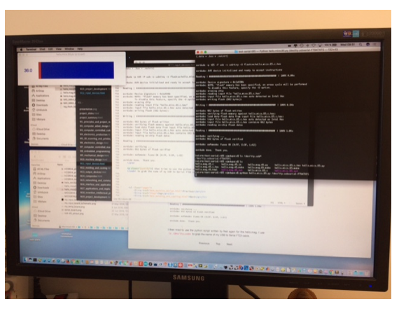
I could see the graphic window with the red bar. It does not change a lot because hopefully the ozone concentration in my office does not change. I tried to touch the sensor and then I could see a change meaning that the sensor is sensitive also temperature and potentially humidity. In the python script, the scale is 0-1023 and the max value should correspond to a 5V voltage. This gave me about 146 mV for a reading of 30. With 1k load resistance, I could calculate a value of the sensor resistance of (5/(30/1024*5)-1) = 33k which is in the range indicated in the datasheet (although a bit high).
The kicad files, ATTiny firmware and python script can be downloaded below (or in the section Files to download, top right panel):
- kicad .pro file: hello-mics.pro
- schematics: hello-mics.sch
- board: hello-mics.kicad_pcb
- firmware: hello.mics.85.c
- makefile: hello.mics.85.make
- python script: hello.mics.85.py