16. Interface and Application Programming
Week 16:
Group Assignment
List of program candidates…of interest to me
- Dart (on Flutter)
- Processing
- Blynk
- APP Inventor
- Grasshopper (on Rhino)
Link to group page here
Individual Assignment
- Develop an App and UI to interact with Input or Output boards
The Plan
- Develop an Android control app to control (output instructions to) RGB LED (Neopixel) board…change the RGB color…by touching colors on a colorwheel of a UI
- Develop an Android control app to control (output instructions to) Servo board…move servos a specific amount…by moving a slider bar from 0 to some value up to 360.
For my final project, I would hope to develop a smartphone App with the following functionality...
- Make adjustments to the RGB illumination associated with ‘Braking’ and ‘Fun’ programs…adjust specific hue, blink rate, sensitivity to Accelerometer force, etc.
- Make adjustments to photo transistor sensitivity…to control auto on/off, and to also do manual on/off of device
- Turn on/off the auto wing angle feature associated with the gyro sensor (disable input signals from the Gyro?) and allow the wing angle to be specified and fixed
- Provide a battery level indicator…receive a signal from the battery and display a notification if the battery is running low
The Procedure
Try out a few UI programming languages…
- Flutter
- Processing
- Blynk
1. Flutter
Installing Flutter
- Install Flutter SDK
- Added ‘Flutter/bin’ Path in Environmental Variables
- Install Android Studio
- Install Google USB Driver
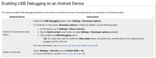
- Enable Android smartphone for Debugging work
- Run ‘flutter doctor’…resolve errors
- In Android Studio…File > Settings…to install plugins (Dart & Material)
- Watch tutorial videos
- Try to make a simple Android APP to control color…by modifying example Apps to interact with an Input or Output device (need to decide)
Learning Flutter
Completed this tutorial to get an cursory understanding of Flutter. Learned to…
- Get familiar with the Android Studio IDE
- Get familiar with the structure and syntax of the Dart programming language used in the Flutter SDK
Here is a simple ‘Hello World’ program in Dart…utilizing ‘Material’ UI package
import 'package:flutter/material.dart';

void main() => runApp(MyApp());

class MyApp extends StatelessWidget {
  @override
  Widget build(BuildContext context) {
    return MaterialApp(
      title: 'Welcome to Flutter',
      home: Scaffold(
        appBar: AppBar(
          title: Text('Welcome to Flutter'),
        ),
        body: Center(
          child: Text('Hello World'),
        ),
      ),
    );
  }
}
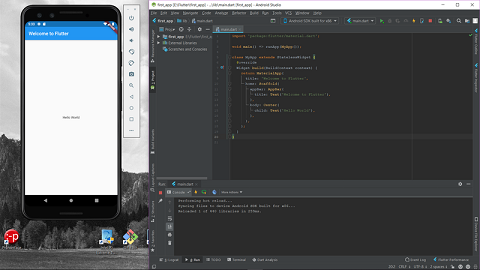
- Run code on an Emulator
- Make adjustments to code (changed a string) while it is still running and ‘Hot Reload’ to immediately see changes
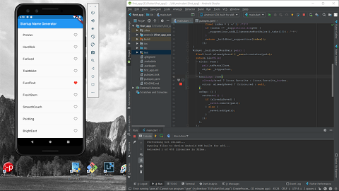
- Made additional changes to the code to get interactive buttons (heart icon in Red) and change colors of UI items (Top Bar in White)
Tuesday, 14:00pm…Running out of time…will leave the Flutter spiral here for now and move on to a programming platform that might be a less steep learning curve for me to complete this week’s assignment.
Flutter - Learning Outcome
- The installation process was rather cumbersome…does it need to be this way?
- Has the potential to make very beautiful, high configurable, highly functional, professional grade mobile phone UI to control various ‘Output’ boards
- Code once and can compile to native Android or iOS native code…very versatile
Moving on to a different program…
2. Processing
Installing Processing
As simple as downloading and running an executable file…and I am in the Processing programming environment…ready to code.
Lots of great code examples to do many things in the Processing program, I looked at…
- Button
- Handles

- Scrollbar

…as possible UI elements to control my RGB and Servo output boards.
But…how to send signals from Processing to the board? According to the arduino website here…for Processing to control the Arduino, an Arduino library and firmware must be installed into Processing. A Standard firmware program, called ‘Firmata’, is uploaded to the board and communication between Processing and Arduino is made possible with the library.

- I downloaded the Firmata firmware and library here
- I unzipped and saved the Arduino library folder into the Processing Sketchbook/Libraries folder
- Getting the Arduino and Processing to communicate with the help of this excellent instructions from Sparkfun here
Successfully got Arduino to send Processing a ‘Hello World’ message over and over.
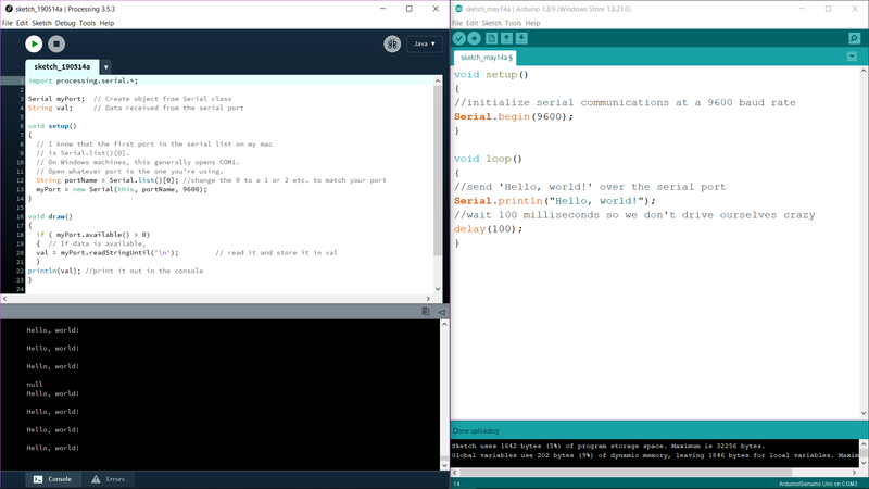
Code on the Arduino SEND side…
void setup()
{
//initialize serial communications at a 9600 baud rate
Serial.begin(9600);
}

void loop()
{
//send 'Hello, world!' over the serial port
Serial.println("Hello, world!");
//wait 100 milliseconds so we don't drive ourselves crazy
delay(100);
}
Code on the Processing RECEIVE side…
import processing.serial.*;

Serial myPort;  // Create object from Serial class
String val;     // Data received from the serial port

void setup()
{
  // I know that the first port in the serial list on my mac
  // is Serial.list()[0].
  // On Windows machines, this generally opens COM1.
  // Open whatever port is the one you're using.
  String portName = Serial.list()[0]; //change the 0 to a 1 or 2 etc. to match your port
  myPort = new Serial(this, portName, 9600);
}

void draw()
{
  if ( myPort.available() > 0)
  {  // If data is available,
  val = myPort.readStringUntil('\n');         // read it and store it in val
  }
println(val); //print it out in the console
}
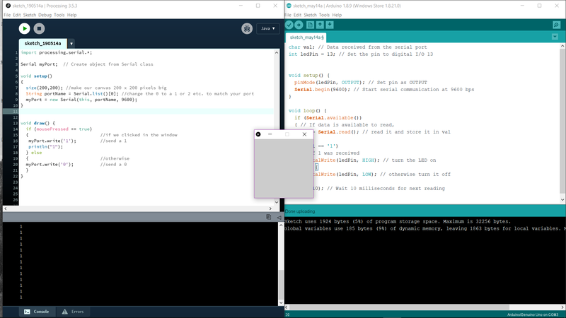
Now to go the other way, sending instructions from Processing to Arduino…
Code on the Processing SEND side…
import processing.serial.*;

Serial myPort;  // Create object from Serial class

void setup()
{
  size(200,200); //make our canvas 200 x 200 pixels big
  String portName = Serial.list()[0]; //change the 0 to a 1 or 2 etc. to match your port
  myPort = new Serial(this, portName, 9600);
}


void draw() {
  if (mousePressed == true)
  {                           //if we clicked in the window
   myPort.write('1');         //send a 1
   println("1");
  } else
  {                           //otherwise
  myPort.write('0');          //send a 0
  }
}
Code on the Arduino RECEIVE side…
char val; // Data received from the serial port
int ledPin = 13; // Set the pin to digital I/O 13


void setup() {
  pinMode(ledPin, OUTPUT); // Set pin as OUTPUT
  Serial.begin(9600); // Start serial communication at 9600 bps
}

void loop() {
  if (Serial.available())
  { // If data is available to read,
    val = Serial.read(); // read it and store it in val
  }
  if (val == '1')
  { // If 1 was received
    digitalWrite(ledPin, HIGH); // turn the LED on
  } else {
    digitalWrite(ledPin, LOW); // otherwise turn it off
  }
  delay(10); // Wait 10 milliseconds for next reading
}
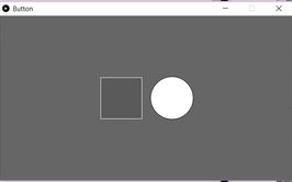
Successfully got Processing to send a serial WRITE signal to the Arduino…when a mouse click occurs over a grey square generated by Processing.
OK…with the completion of the tutorial, I can now get Processing to communicate with Arduino both as signal sender and receiver…over a physical USB serial connection. As a review, this required…
- A serial library usage in Processing
- The definition of a COM port and Baud rate that is the same on both sides of the communication ends
Driving my RGB Board with a Processing UI
The Objective: Write simple programs in Processing and Arduino so that when the mouse cursor moves over the Processing generated button, the RGB LED on my RGB board will change from a ‘Steady Red’ illumination to ‘Changing Color’ illumination program.
In Processing:
-
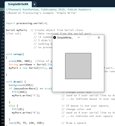
Used the Processing example program ‘Simple Write’ as the base program
-
Made some small modifications..
-
Enlarged the UI window size from 200 x 200 to 300 x 300
-
Increased the UI button size from 100 x 100 to 150 x 150
-
Adjusted the ‘mouse over’ parameters to account for the larger window and button size
- The program will send a ‘Y’ character to the Arduino by means of serial communication when the mouse cursor moves over the button…made possible by importing the Processing Serial library, defining a serial class object…and in the setup routine, look for the active serial communication port and activating the port to communicate at 9600 baud.
import processing.serial.*;
Serial myPort;

void setup()
{
  String portName = Serial.list()[0];
  myPort = new Serial(this, portName, 9600);
}
The Processing program in its entirety is here…
//Phanuwit Kanthatham, FabAcademy 2019, FabLab Kamakura
//Based on Processing's example 'Simple Write'


import processing.serial.*;

Serial myPort;  // Create object from Serial class
//int val;        // Data received from the serial port
                  // (I commented out this line because
                  // I didn't think it was needed...
                  // nothing being sent from Arduino side
                  // to processing side)

void setup()
{
  size(300, 300);  //Size of graphics window
  String portName = Serial.list()[0];
  myPort = new Serial(this, portName, 9600);  //Finds active COM port...6 in my case
                                              //sets communication rate at 9600
}

void draw() {
  background(255);
  if (mouseOverRect() == true) {    // If mouse is over square,
    fill(204);                      // change color and
    myPort.write('Y');              // send an Y over serial line to Arduino
                                    // ...to indicate mouse is over square
  }
  else {                            // If mouse is not over square,
    fill(0);                        // change color and
    myPort.write('N');              // send an N over serial line to Arduino
                                    // ...to indicate not over square
  }
  rect(75, 75, 150, 150);           // Draw a square
}

boolean mouseOverRect() { // Test if mouse is over square
  return ((mouseX >= 75) && (mouseX <= 225) && (mouseY >= 75) && (mouseY <= 225));  //This series
                                                                                    //of Boolean statements
                                                                                    //sees whether the mouse
                                                                                    //position is within
                                                                                    //the area defined by the
                                                                                    //square as defined by
                                                                                    //mouse position relative
                                                                                    //to left and top of the
                                                                                    //window area
}
In Arduino:
-
Based on the Adafruit example RGB program, I wrote code to have the RGB flash Red, Green, Blue when the character ‘Y’ is received (triggered by the mouse cursor moving over the Processing button) from Processing via serial communication.
-
To make this possible, I imported the SoftwareSerial library (the ATTiny45 on my RGB board doesn’t have hardware serial capability), created a serial class object, activated serial communication at 9600 baud
#include <SoftwareSerial.h>
SoftwareSerial mySerial(3,4);
void setup()
{
  mySerial.begin(9600); // Start serial communication at 9600 bps
}
- The Adafruit code instructed that an important line of code needed to be utilized if running a Common Anode RGB LED (which I was).
#define COMMON_ANODE // The CREE CLV1A-FKB is a Common Anode RGB
- Furthermore, because I am operating my board using Arduino code, I had to make sure that I used Arduino pin designations for the ATTiny45 pins used as RGB signal pins…so rather than defining my RGB pins as 5, 6, 7…I called them the equivalent Arduino designations 0, 1, 2


- Also, I think because SoftwareSerial is being used, an interesting quirk in the program was required…function sub-routines (‘SetColor’ in my case) other than ‘Setup’ and ‘Loop’ need to be placed BEFORE ‘Setup’…for the program to compile without error
The Arduino code…
// Phanuwit Rico Kanthatham, Fabacademy 2019, FabLab Kamakura
// Based on code by...Adafruit Arduino - Lesson 3. RGB LED

#include <SoftwareSerial.h>
char val; // Data received from the serial port

SoftwareSerial mySerial(3,4);

int redPin = 2; //Arduino pin designations
int greenPin = 0; //...not ATTiny45 pin designations
int bluePin = 1;

//uncomment this line if using a Common Anode LED
#define COMMON_ANODE // The CREE CLV1A-FKB is a Common Anode RGB

void setColor(int red, int green, int blue)
{
  #ifdef COMMON_ANODE
    red = 255 - red;
    green = 255 - green;
    blue = 255 - blue;
  #endif
  analogWrite(redPin, red);
  analogWrite(greenPin, green);
  analogWrite(bluePin, blue);
}

void setup()
{
  mySerial.begin(9600); // Start serial communication at 9600 bps
  pinMode(redPin, OUTPUT);
  pinMode(greenPin, OUTPUT);
  pinMode(bluePin, OUTPUT);
}

void loop(){
 while(mySerial.available()) { // If data is available to read,
 val = mySerial.read(); // read it and store it in val
 }
 if (val == 'Y'){
  setColor(255, 0, 0);  // red
  delay(500);
  setColor(0, 255, 0);  // green
  delay(500);
  setColor(0, 0, 255);  // blue
  delay(500);
 }
 else{
  setColor(255, 0, 0);  // red
  delay(500);
 }
}
Success!! The video showing the RGB illumination changing from ‘Steady Red’ to ‘Changing Color’ is here…
3. Blynk
Installing Blynk
Unlike the others, this software installs into the mobile phone…not the PC. The Blynk website promises…”Build an IoT App in 5 Minutes”. Sounds good to me.
Followed this Blynk tutorial here to install all necessary files on the PC and run an example ‘Terminal’ sketch via ‘Serial USB’ connection.


Installing and Using the Blynk App on an Android Smartphone
- Downloaded and Installed Blynk using Google Playstore
- Registered Username and Password with BLYNK
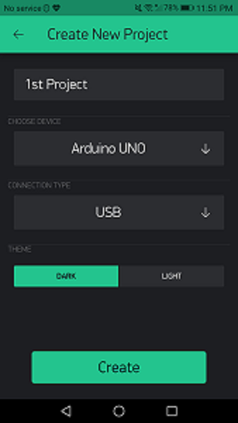
- Create a new project (a ‘Terminal’ program) by specifying the ‘Arduino Uno’ as the device and ‘USB’ as the connection method
- In the project interface…
- Added a ‘Terminal’ widget, specifying the ‘Input Pin’ as ‘V1’
- Added a ‘Button’ widget, specifying the ‘Output Pin’ as ‘D13’
Setting Up and Using the Blynk App on the PC and Arduino IDE
- Downloaded and installed Arduino ‘Libraries’ and ‘Tools’ into the Arduino ‘Sketchbook’ folder
- Got Arduino code for the ‘Terminal’ program from Blynk here
- Lauched Arduino IDE and paste code…
- making sure that the ‘Input’ and ‘Output’ pins are the same as in the mobile App (V1 and D13)
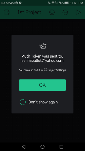
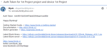
- …and pasting the ‘Auth Code’ that the mobile App sent to my email into the Arduino code at char auth[] = “(token code)” line
- Open Command Prompt terminal to run script to connect the Arduino to the internet and allow communication with the Blynk Mobile APP…fail!!
The video tutorial is for Mac users. The solution for Windows users I found at the Blynk Help Center under the category USB Serial here. The article describes internet connection script usage for Windows/Mac/Linux.
What I needed to do was…
- Edit the .Bat file in the script folder changing the COM port from 1 to 3…which is the port where my Arduino is connected.
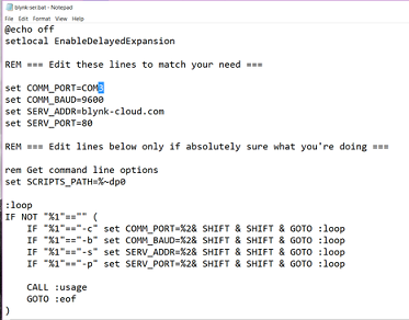
- Save the edited .Bat file
- Run the newly edited and saved .Bat file by double-clicking the icon for the file

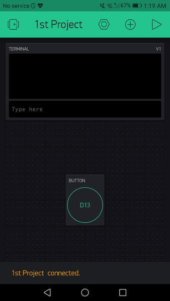
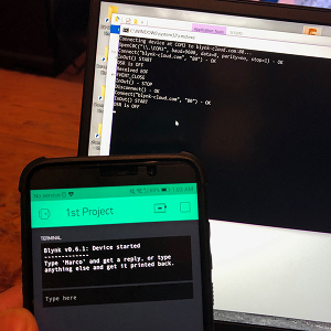
The script runs and creates a success connection, allowing the Arduino code to run on the mobile phone…
The code copied into Arduino IDE as follows…
#define BLYNK_PRINT SwSerial

#include <SoftwareSerial.h>
SoftwareSerial SwSerial(10, 11); // RX, TX

#include <BlynkSimpleStream.h>

// You should get Auth Token in the Blynk App.
// Go to the Project Settings (nut icon).
char auth[] = "cfe7354ee8454e96b8fe89871a73274b";

// Attach virtual serial terminal to Virtual Pin V1
WidgetTerminal terminal(V1);

// You can send commands from Terminal to your hardware. Just use
// the same Virtual Pin as your Terminal Widget
BLYNK_WRITE(V1)
{

  // if you type "Marco" into Terminal Widget - it will respond: "Polo:"
  if (String("Marco") == param.asStr()) {
    terminal.println("You said: 'Marco'") ;
    terminal.println("I said: 'Polo'") ;
  } else {

    // Send it back
    terminal.print("You said:");
    terminal.write(param.getBuffer(), param.getLength());
    terminal.println();
  }

  // Ensure everything is sent
  terminal.flush();
}

void setup()
{
  // Debug console
  SwSerial.begin(9600);

  // Blynk will work through Serial
  // Do not read or write this serial manually in your sketch
  Serial.begin(9600);
  Blynk.begin(Serial, auth);

  // This will print Blynk Software version to the Terminal Widget when
  // your hardware gets connected to Blynk Server
  terminal.println(F("Blynk v" BLYNK_VERSION ": Device started"));
  terminal.println(F("-------------"));
  terminal.println(F("Type 'Marco' and get a reply, or type"));
  terminal.println(F("anything else and get it printed back."));
  terminal.flush();
}

void loop()
{
  Blynk.run();
}
Appendix - Research
Processing
- An open source language/development tool for writing programs in other computers
- …for letting computers “talk” with an Arduino
- Write ‘Processing’ and ‘Arduino’ programs and have them talk to each other.
- To control an ‘Arduino’ board with a ‘Processing’ program…use a ‘Processing’ library in ‘Arduino’
- The ‘Processing’ library can control an Arduino board without having to write Arduino code…only need to upload a standard firmware (program) to the Arduino board…communication made possible by the library (codes).
- ‘Firmata’ is the name of the firmware…included in Arduino Software
- ‘Processing’ communicates with ‘Arduino’ by means of serial communication…for high speed serial data monitoring, use a ‘Processing’ window and a ‘draw()’ command…not a generic console window.
Jeremy Blum: Serial Communication and Processing A good instructional video here.
-
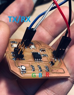
TX/RX serial communication
-
Digital pin 0 and 1 on Arduino can be used for Input/Output functions while the program is running…but ‘multiplexed’ during programming to be used as programming pins for the Arduino
-
TX = Transmit
-
RX = Receive
-
Arduino TX pin connected to Computer RX pin…and vice versa…to enable serial communication
-
Serial Interface…reconciling voltage differences
-
Computer: Operate at +/- 15V (Logic 1 = -15V , Logic 0 = +15V)
-
Arduino: Operates at 0V to 5V (TTL = Transistor Transistor Logic…Logic 0 = 0V, Logic 1 = 5V)
-
A ‘Converter Chip’ translates between the voltages of the different logic types