12. Output devices
Week 12: Electronics Round 2…ding, ding, ding! Round 1 was rough beating. I took many more punches than landed them, I was down for the count a handful of times…but with a bit of sleep and reflection…I came away realizing that I learned a bunch of stuff from the mistakes I made. For this week, I decided to put the ‘Input’ assignment aside for now and focusing on getting ‘Output’ right…putting to work all of the learning outcomes from the Round 1 beating to good effect.
Assignment Requirements:
- Add an output device to a microcontroller board you’ve designed and program it to do something
- Demonstrate workflows used in circuit board design and fabrication Implement and interpret programming protocols
- Describe design and fabrication process using words / images / screenshots, or linked to previous examples.
- Explain the programming processes you used and how the microcontroller datasheet helped you (…need to do)
- Outlined problems and how you fixed them (…need to do)
- Included original design files and code (…need to do)
The Plan
A ‘Manageable Spiral’ and “Supply Side’ time management are the mantras this week. The aim is not to overreach, but instead to complete required assignment tasks and hopefully generate some useful learning outcomes
- Sketching and Fabricating an Output board (maybe two) following Neil’s examples and instructions closely…reinforce learnings from previous weeks, trying to avoid making the same mistakes.
- Upload Neil’s program to the built board(s)…aim to successfully complete the procedure…and if time permits, make an effort to understand the code underlying the program(s).
- Run the program to test the board(s)…as validation for correct fabrication and correct programming procedure.
Preparations:
I decided to work with Neil’s RGB and Servo boards…again, because they are relevant to my final project (lighting effect control and ‘wing’ actuation). Including last week, I will have at the end of this week’s work sessions…completed initial investigations into 3 crucial components for my final project…Accelerometer, Servos, and RGBs.
Prior to the Saturday work session, I used Eagle to layout the two boards. This in attempt to allow available time during the work session to be utilized for circuit board fabrication, programming and testing…and for completion of the Group Project.
Datasheet Understanding/Application: Pulse Width Modulation
For both output devices intended for this week, the data signal type that will need to be sent from the Microcontroller to both the Servo and RGB LED is a specific type called ‘Pulse Width Modulation’ or ‘PWM’ for short. In my understanding, the need for PWM signals in these instances has to do with a digital device (the Microcontroller) generating an Analog-like signal. Digital devices have 2 logic states only, ON or OFF…represented in code as a 1 or 0 and manifesting electrically (in the case of AVR chips) as 5V or 0V. But this binary state cannot fully utilize the range of function in certain output devices, like Servos and RGB LEDs. Hobby servos can rotate very precisely between 0 degrees and 180 degrees…180 possible positions it can take…not just 2. Likewise, RGB LEDs can be instructed to output a range of 255 different colors and 255 levels of brightness…not just be turned ON and OFF. To access the full range of capabilities of these output devices, PWMs need to be used.
With a little YouTube research here, here, here, adn here I learned that PWMs…
- Vary the power going to an electronic device by quickly turn power on a signal pin ON/OFF…at a certain frequency and with a certain Pulse Width
- A square wave of which the HIGH state can be controlled…the key parameters are the wave ‘Amplitude’ (the difference between Vmin and Vmax), ‘Cycle Time’ (the time required for one wave pulse to run, ‘Frequency’ is 1/Cycle Time), and ‘Duty Cycle’
- Duty Cycle = is the Pulse Width of the HIGH state (@ Vmax), used to specify how long a signal is turned ON vs turned OFF (ex: 50% Duty Cycle means ON 50% of the time and OFF 50% of the time, 25% Duty Cycle means ON 25% of the time while OF 75% of the time)
PWM and LEDs - Flicker Fusion Rate = 18 times/second…the ON/OFF switching rate above which humans can no longer visually perceive ON/OFF and see only continuous ON. - Most LEDs controlled by PWM operate at a switching frequency rate of 100 times/second or 100Hz (i.e. much faster than the Flicker Fusion perception rate) - Increasing the Duty Cycle percentage while switching at a 100Hz rate…increases LED Brightness (i.e. 25% Duty Cycle is dimmer than 75% Duty Cycle…@ 100Hz)
PWM and Servos
- Hobby servos typically operate with a Pulse Width of 20ms or 50Hz
- Duty Cycle changes affect servo position in the following ways…1ms Duty Cycle = 0 degree position, 1.5ms Duty Cycle = 90 degrees position, and 2.0ms Duty Cycle = 180 degrees. Positions in between can be achieve by fine tuning the Duty Cycle period between 1ms and 2ms.

PWM on ATTINY44 (SOIC type) - Discussions on PWM for the ATTiny44 is in section 13 (…from page 63-77) of the microcontroller’s datasheet - The ATTiny44’s PWM functions can be accessed via digital Pins 5-8
PWM on ATTINY45 (SOIC type) - Discussions on PWM for the ATTiny45 is in section 11 (…from page 64-81) of the microcontroller’s datasheet - The ATTiny45’s PWM functions can be accessed via digital Pins 3-6
Lab Session:
At the beginning of the session, Caterpillar sensei recommended that we ‘Breadboard’ our chosen Output board, before creating the actual PCB. The reasoning: ‘Breadboarding’ reduces ‘debugging expense’…i.e. cutting, stuffing and eventually discarding boards…because of mistakes with circuit routing and programming, etc. Made tons of sense to me…especially since I never made it to ‘programming’ and ‘testing’ during the ‘Input’ week. I decided to ‘breadboard’ Neil’s ‘Servo’ board.
1. Breadboard Prototyping - Servo Board


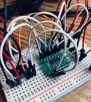


The process took a while, as I have limited breadboarding experience and also never dealt with this many components with so many different pins. Translating Neil’s circuit routing diagram to the breadboard was challenging, but really forced me to understand how the pin from one component connects to the pin from another component. This may be just my imagination, but I felt the physicality of breadboarding (vs Eagle circuit routing) aided to my understanding of the workings of the Servo board. Of course I made mistakes…
- Putting pins from different components into the same row in the breadboard…because I wanted to maintain the adjacency of the components as it was in Neil’s diagram. Ofcourse, this led to problems as different signals cannot share the same ‘channel’ on the breadboard
- Silly basic mistake…forgetting a couple of ground lines as a necessary pair to power lines
Significant Learning Outcome: Program Boards via ISP…IDE unnecessary!!!
- Last week, I assumed I had to copy Neil’s code into an IDE (Atmel Studio in my case) and use it to compile and upload it to the board via in ISP connection…I was wrong.
- Mad Hatter sensei reminded me that I didn’t need to do this…that I could save the files to a folder on my PC and upload it directly to my board.
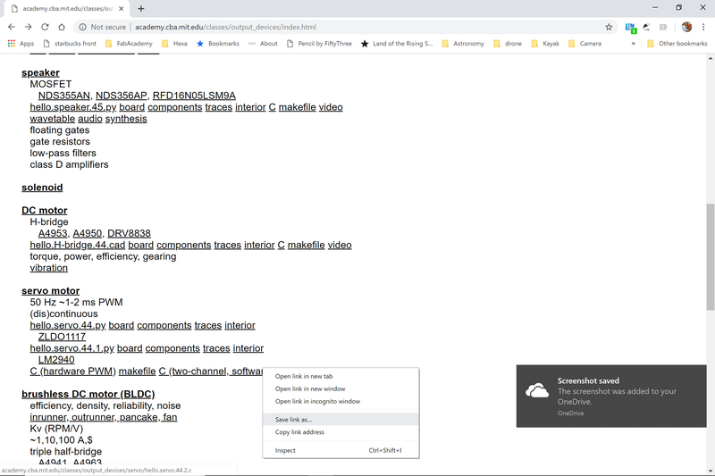
Procedure: Uploading Code Directly to a Board using the FabTinyISP (initially learned Week 07). This technique utilizes weblinks to code and make files that Neil provides in weekly assignment pages.
-
Right-click the link that Neil provided…for C code and Makefile
-
Choose “Save link as”
-
Save the “Code” file ([file name].c) and associated “Make” ([file name].make) file into the same folder (…the path to this folder will need to be specified later, so remember it)
-
Launch a ‘Git Bash Terminal’ window and use it ‘CD’ (referrencing the file path from the last step) to the directory where the C code and make files were saved
-
Use 3 (some times 2) commands in a terminal (ex: Windows Command Prompt, Git Bash, etc.) to upload the program to the new board. While the structure of the 2-3 commands are the same, some modifications the commands will be necessary (specifying a different microcontroller, location of files, etc.). The example set of bash commands from Week 07 is here

The commands for the servo project:
- make -f hello.servo.44.2.make…sets up the FabTinyISP to program the ATTINY44)
- make -f hello.servo.44.2.make program-usbtiny-fuses…manages the external Resonator on the board?
- make -f hello.servo.44.2.make program-usbtiny…compiles C-code to hex and uploads to the ATTINY44
Servo Board Result
Success! It’s alive!!
Time to make the PCB version…
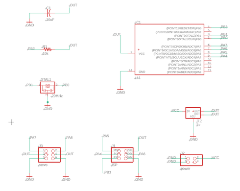

Schematics and Routing went reasonably well in Eagle. Getting Power and Ground lines to the Microcontroller, Servo pins and ISP pins did prove to be a challenging routing puzzle…which I ended up getting wrong…I didn’t ground the Microcontroller and ISP pins (fixed in the routing image above)…requiring a wire bridge after ‘stuffing’.

Stuffing went fast. Few parts and many of them large. Only the Microcontroller (double checked the correct orientation), Resistor and Capacitor required a little more attention.

Programing - Servo Board
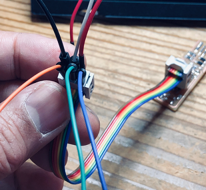
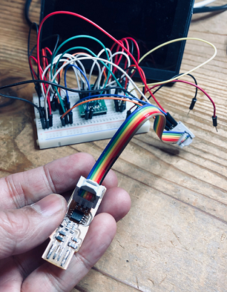
Stuffing done, the FabTinyISP was connected to the new Servo PCB. The same process used to program the breadboard prototype above utilized…
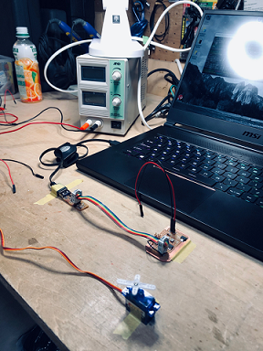
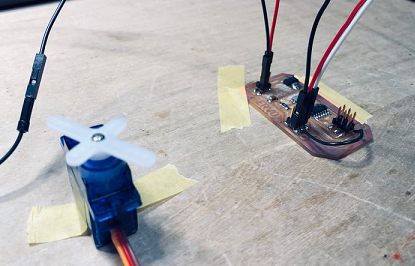
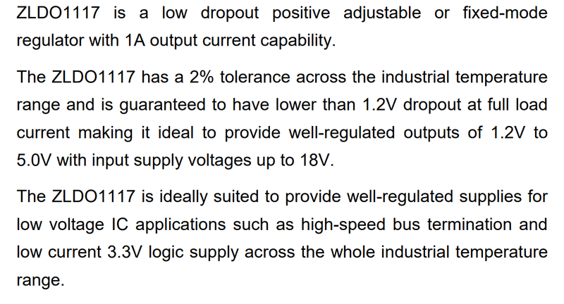
Programming went smoothly…I connected up the little servo again and gave it 6.3v (the ZLDO1117 Regulator’s datasheet specifies a 1.2v ‘Dropout’ voltage…so I added that amount to the 5.5v minimum required by the regulator)
from the power supply, and…
Woo hoo!!!
For my final project, I worked with servo control once again. Working with a base Arduino sketch, I made adjustments to create a simple program to set the zero spindle position, then move the servo spindle to a specific rotation angle (135 deg), pause and return to the starting position. My modified code is here…
// Phanuwit Kanthatham, Fab Academy 2019, FabLab Kamakura

# include <Servo.h>   //Servo library

Servo servoLeft;      // creating a servo object called "servoLeft"

void setup() {
  servoLeft.attach(0);    // Attaches servoLeft to digital pin 9
  servoLeft.write(0);     // Sets servo start position to zero angle
  delay(2000);        // 2 seconds delay

}

void loop() {

  servoLeft.write(135);   // Rotates servo spindle to 135 degrees
  delay(1000);
  servoLeft.write(0);     // Returns servo spindle to home...zero angle
  delay(1000);

}
I tested this program on both the servo board I built in week 12 and on my MCU for the final project device.
Servo Board learnings
- While I am able to control the servo’s spindle position, I cannot yet figure out how to control the speed of rotation.
- The servo movement is more abrupt than I like, lashing when the program loop ends. When hooked up to external power, I can observe a current draw spike when the servo lashes or when it meets with enough rotational resisting force.
- In the future, when my programming skill improves, I hope to look into managing power delivery to the servo to result in smoother…lash free movement.
- The SoftwareServo library rather than the typical Servo library needs to be used when working with the Attiny chipset (not supported by the standard Servo library)
2. PCB Production - The RGB Boards
Giddy with partial success on the Servo Board, I decided to forego the intelligent and useful ‘breadboarding’ prototyping stage and jump straight into the production of another output board - the RGB Board.
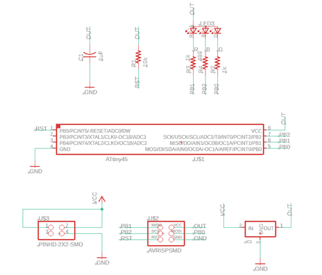
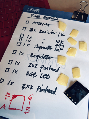
Neil’s RGB board is not overly complicated. 10 components only. The usual suspects…Microcontroller (ATTINY45), a 2 x 3 ISP Pin Header, and a 2 x 2 Power Pin Header (no FTDI connector on this board!). The featured component is the CREE RGB LED (CLV1A-FKB, datasheet here)…
From the component datasheet…
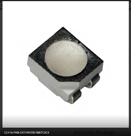
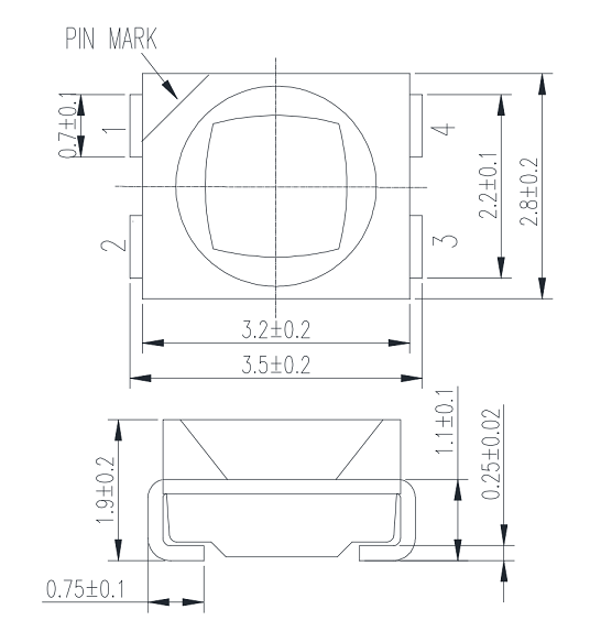
4 pads on the bottom of the RGB LED component…Red, Green, Blue and a common anode (negative). Additionally…
- 1x 5V Regulator, with..
- 1x 1uF Capacitor, and…
- 1x 10k Resistor to manage output power to the Microcontroller
- 3x Resistors manage power to the LEDs
- 2x 1k Ohm, for R & G and…
- 1x 499 Ohm, for B
Schematics and trace routing work on Eagle went pretty smoothly, with traces under the Microchip and LED’s Resistors being a little challenging.
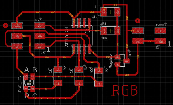
PNG image files (monochrome, 800dpi) of the traces and board outline were saved when routing work was completed and digital error checks (DRC) passed.
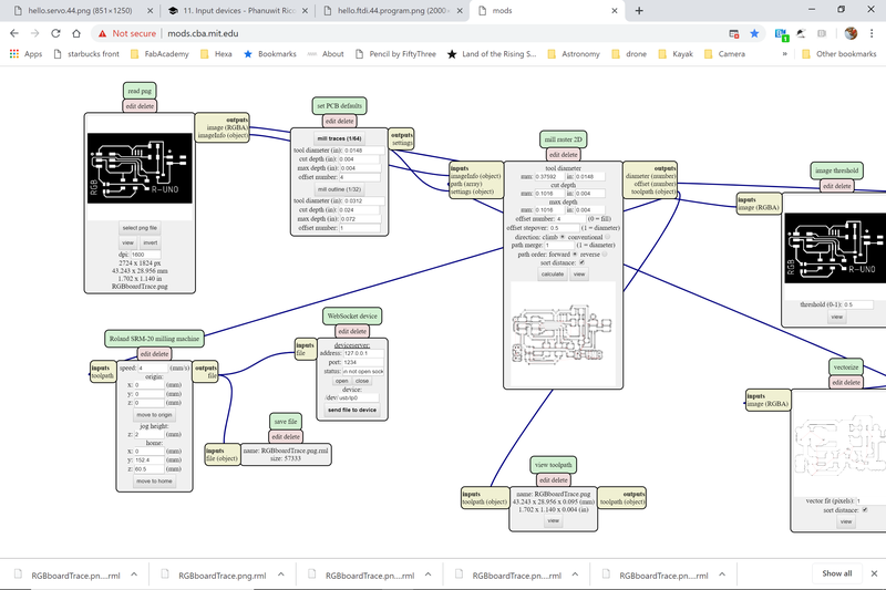
MODS conversion of the PNG to toolpath RML files also went smoothly. Only the small, narrow pads of the Microcontroller posed a problem. I used to ‘cheat’ in MODS (rather than return to Eagle to make adjustments to pad or line widths) to reduce the actual 1/64” (0.01525”) end mill diameter down to false 0.0149” diameter to allow for all the pads to be separated by tool paths.

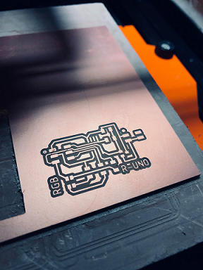
Milling went smoothly. The results were good.
“Stuffing” has also become routine now (strange to be saying that). The Microcontroller soldering feels like a piece of cake compared to the Accelerometer (which I still can’t get right). Like the Microcontroller, getting the orientation of the RGB LED is important and I checked twice before putting hot solder to leads. Following advice from internet soldering tutorials, I prep most of my pad soldering by brushing them with flux. It did seem to generate better, shinier solder joints…though it left the board with a sticky appearance. RGB board done…conductivity tests revealed no issues.

Time to program…
Similar to the Servo breadboard programming, I used the terminal command line to run a series of commands (utilizing files saved in the same directory where the commands are being run) to program the freshly minted RGB board.
The commands or my RBG LED project:
Only 2 are needed for this board. No need to adjust fuses (because no external clocks/resonators utilized)
- make -f hello.RBG.45.make..prepares the FabTinyISP to program the ATTINY45 RGB board
- make -f hello.RGB.45.make program-usbtiny…compiles Neil’s C-code to machine language and uploads to the RGB Board
RGB Board Result
I literally pumped my fists into the air chanting ‘RGB, RGB!!’ when the board’s LEDs lit up. It feels great to succeed…as modest the task and victory was.
Files
Servo Board Schematics here
Servo Board Routing here
Servo Board Outline image here
Servo Board Trace image here
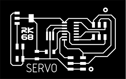
Servo Board Outline RML file here
Servo Board Trace RML file here
RGB Board Schematics here
RGB Board Routing here
RGB Board Outline image here
RGB Board Trace image here
RGB Board Outline RML file here
RGB Board Trace RML file here