9. Embedded programming
Week 9 Entering the Matrix…10 hours in, and I really asked myself…if I shouldn’t have taken the blue pill. There’s never an easy week at FabAcademy and this week was no exception. Felt like Neo in the Matrix, waking up to a new reality but struggling to make sense of it all. There was English everywhere…but now it has been configured and ‘compiled’ by a completely new ‘logic operand’. After a full day at it…I am beginning to understand…like Neo, I learned to let go, accept and embrace the new physics…and it feels liberating and powerful.
The Group Assignment page is here
The Assignment Requirement:
- Upload a program onto the EchoHelloBoard (made in week 07)
- Read the Atmel datasheet
Assignment 1: Programming the EchoHelloBoard
This section is basically a review and hands-on expansion of the procedures learned briefly in Week 07.
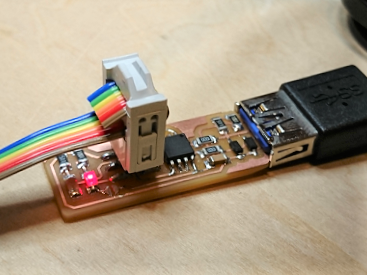
- Connect the FabTinyISP programmer to the laptop and get it to be recognized as an Atmel USB Device/USBTinySPI. I had trouble with this and had to use Zadig to reinstall the correct Windows driver.
- Launch Zadig
- Choose ‘Options’ > ‘List All Devices’
- Select ‘USBtinySPI’ from the dropdown box below
- Install ‘libusb0 (v1.2.6.0)’
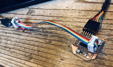
- Connect the target board/microcontroller…the EchoHelloBoard in this case
to the laptop with a FTDI cable…be careful to have the ground wire connected to the ground pin. This powers the board and allows the board to send signals back to the laptop.
-
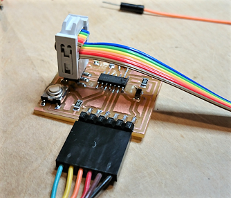
Connect the FabTinyISP to the EchoHelloBoard with a 6-pin ribbon cable…make sure to match wires and pins from one board to the other.
6-Pin Connector:
- VCC - power
- GND - ground
- SCK - Serial Clock
- MISO - Master-in, Slave-output
- MOSI - Master-out, Slave-in
- RESET - tells AVR to enter programming mode
The EchoHelloBoard is now ready to receive a program.
Using Integrated Development Environments to Program the Target Board
To program the Atmel ATtiny44 powered EchoHelloBoard, I will need an IDE to write/debug, compile, upload code into it. The procedure differs slightly from one IDE to the next, but generally follows these steps…
-
Write/Debug code: Done in an IDE using any of a long list of programming languages can be used…there are pros and cons to each. Some are more user friendly (High Level, Natural Language) but tend to generate code that is bulky and inefficient. Others are more cryptic (closer to machine language in syntax) and may be more difficult to use (especially for novices like me) but will generate smaller, more efficient code. As the Atmel ATtiny44 has a limited amount of onboard memory…smaller, tighter, more efficient code is preferred. Write it, make sure it is free of ‘bugs’ or errors…then move on to the next step.
-
Compile Code: This steps converts programming language code into hexidecimal machine language instructions that can be understood and executed by the microcontrollers. In our case, the compiler to be used is the GNU AVR-GCC.
-
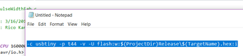
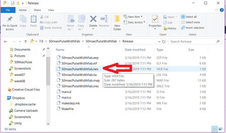
upload Code: With the ‘Hex File’ of the program instructions created, it can be uploaded into the target board/microcontroller via a programmer. For each IDE, the programmer will need to be set up to be recognized as such. The program AVRdude is used to allow IDEs to recognize the USBtiny. Within the IDE, generally, the location of the AVRdude application needs to be specified…as well as code to be run thru AVRdude specifying chip type (-p), programmer type (-c), memory type, location and name of executable Hex File (-U)…contained in a ‘Makefile’ that is saved in the same directory as the rest of your project files (c code, hex files, etc.)
After much internet research, decided to install 3 IDEs for evaluation.
- Arduino IDE
- Atmel Studio IDE
- PlatformIO IDE on Atom
1. The Arduino IDE
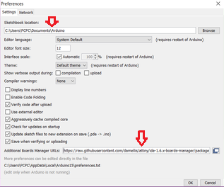
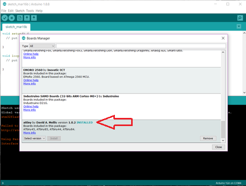
To be able to program the EchoHelloBoard, the ATtiny44 has to be added as a board in the Arduino IDE via the Board Manager function to be supported. The website High-Low-Tech provides detailed instructions to install the ATtiny board into Arduino IDE, here.
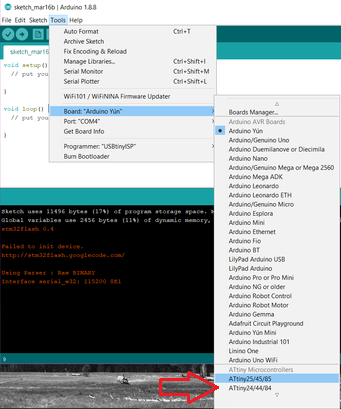
Once installed and selected as the ‘Target Board’ to be programmed, make sure that the settings in the Tools menu is as follows…
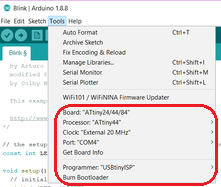
Then…Burn Bootloader to write instructions to external clock. The EchoHelloBoard is now ready to receive a program from Arduino (uploaded via the FabTinyISP).
Programming the EchoHelloBoard with Arduino
I didn’t do anything heroic here, since I cannot really write programs (yet), so I opened Arduino’s Blink program example after which I…
- compiled the code and uploaded it into the EchoHelloBoard.
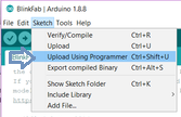
- Use ‘Upload Using Programmer command’…
- The FabTinyISP’s Yellow LED flashes as it processes the program instructions and sends it onwards to the EchoHelloBoard.
- A few seconds later…the Red LED on the EchoHelloBoard blinks. Success!!!
Just to feel a bit like a real programmer…I modified the stock example file a bit, changing the time that the LED is ON and OFF . Can you tell the difference?
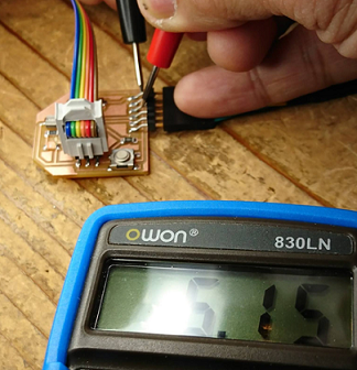
For fun, I check the voltage out of Pin 6 heading to the LED on the EchoHelloBoard with a Multimeter. The reading fluctuates but maxed out at 4.95v…vs voltage in at the FTDI cable of around 5.13v. Hmmmmm…why the voltage difference?
Impression of the Arduino IDE:
- The Arduino IDE is relatively easy to use. Not too many menu options, a clean pleasant interface not overly crowded with scary controls.
- Adding a new board would be difficult potentially, but it seems that there is plenty of 3rd party support to make this just a matter of following instructions.
- Arduino code is easy to read, appears to be like natural language…nothing overly cryptic in the code.
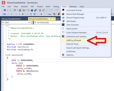
2. Atmel Studio 7 IDE
Launching the Atmel Studio 7 after using the Arduino IDE, one feels the sense that things just got a whole lot more serious. Rather than doing things blindly and wasting time, I visited the Oracle for advice again…found this video “Using USBtiny with Atmel Studio” by D(s)Squared, a tutorial that walks through board programming with the Atmel Studio 7 here.
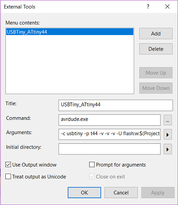
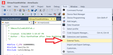
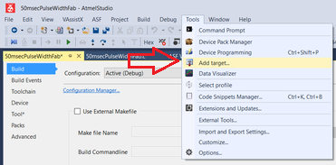
Like with the Arduino IDE, the USBtiny needs to be created as an External Tools (not automatically recognized as a programmer)…using AVRdude
Adding External Tools - AVRDUDE instructions

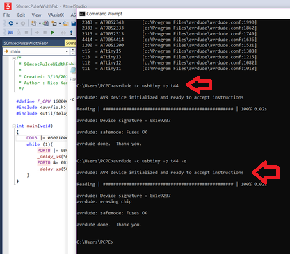
Programmer ready for upload
Adding a new Target Board
Target Board successfully added…
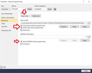
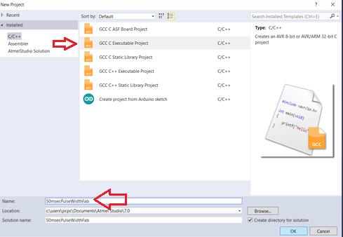
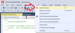
Programming the EchoHelloBoard with Atmel Studio
Opening a new Atmel Studio programming project…
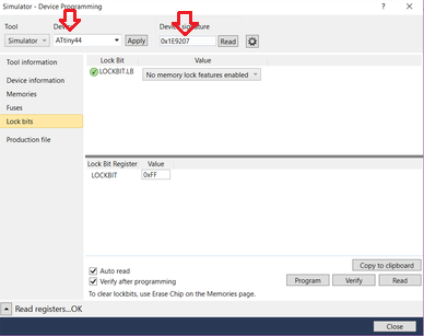
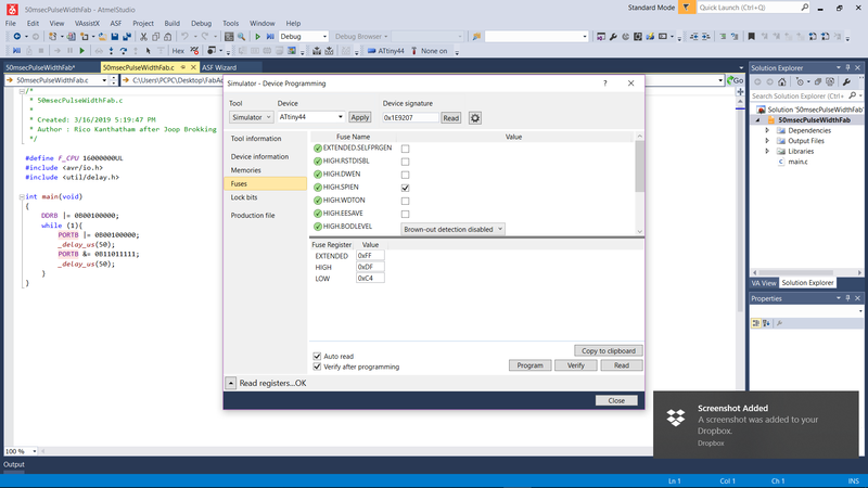
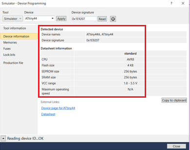
Choose a specific Atmel AVR Chipset (the dropdown box at the top allows for narrowing of choices)…
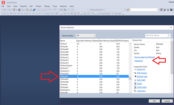
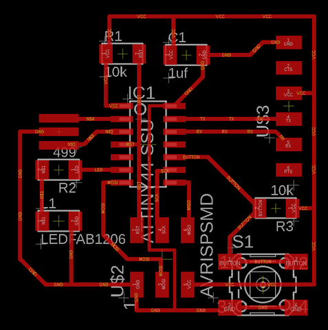
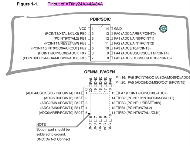
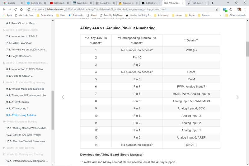
Borrowing C code for a Blink program from the internet (there are many). I make modifications to correctly identify the pin connected to the LED on my EchoHelloBoard (referring to the Atmel Datasheet). My LED is connected to ATtiny44 pin 6 which is named PA7 or ‘Port A number 7’. With learnings from the Elliot Williams video, I was able to successfully use Binary to trigger the specific Register to turn the pin signal High (LED ON) and Low (LED OFF).
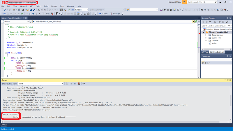
I uploaded the hex file to the EchoHelloBoard using the xxx command in Atmel Studio, but then…
I hit a snag. The build/compile was successful, as was the upload process. But the EchoHelloBoard does respond as expected…the LED does blink.
- I checked the voltage at the FTDI cable…good, 5.15v
- I checked the voltage of Pin 6 with the multimeter…0.01v. An Output signal is not being generated
- I am pretty certain that the issue is with the way I am specifying the clock speed in the code. The code I copied refers to an internal clock while the EchoHelloBoard utilizes a 20MHz External Resonator. I will have to figure out how to fix the code at some point in the future…when I have more time.
Impression of the Atmel Studio 7 IDE:
- Atmel Studio 7 (AS7), natually, has more specific support for Atmel AVR chips. Specifications and datasheets, for example, can just be pulled up within the IDE.
- As learned, programming in C will produce a more efficient code to use in the limited memory ATtiny44 chip. It is clear that gaining expertise with AS7 will allow the programmer to take full advantage of the AVR chip capabilities
- After using AS7 for a while and getting used to the interface, the intimidation factor drops and the understanding of the potential of the IDE increases.
- I suspect I will be on AS7 more and more as I program the AVR chipset more and more.
3. PlatformIO
I love the Atom environment for Markdown. I also have Github integrated into it (used it once). Naturally, was keen to have an IDE that is integrated into Atom. Installed the package…
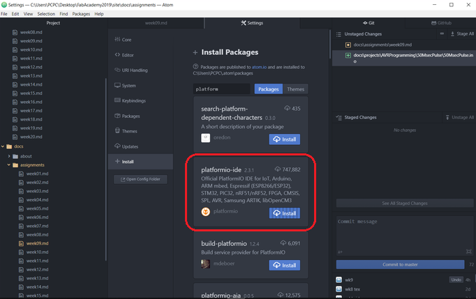
but no time to use…yet. Stay tuned…
Assignment 2: Reading the datasheet
The Datasheet…is my Frenemy
I made a mistake…trying to tackle this technical, reference manual front to back. It didnt’ take more than a couple dozen pages before my eyes…and brain…glazed over. New strategy…it’s time to go see the ‘Oracle’…aka YouTube…and discovered this gem. It is the perfect preface to reading the Atmel ATtiny datasheet, providing a solid overview of concepts that is relevant to making sense of the cryptic datasheet content.
Datasheet Dive Preparation
It’s over an hour long and the video is kinda dull and slow at the beginning…but give it time…”Programming AVR Microcontrollers in C”, a webcast by Elliot Williams will make you feel empowered.
O’Reilly Webcast: “Programming AVR Microcontrollers” video by Elliot Williams…an overview before tackling the datasheet head-on. The EXCELLENT and HIGHLY RECOMMENDED video here
…and this overview of the AVR Microcontroller on Wiki
Some key takeaways…
- C is an old language, but it is efficient and very relevant to microcontrollers with limited onboard memory
- C code is much faster than Arduino code…because it does not have a code bloating, user-friendly front end to bog things down
- The Atmel AVR ‘speaks’ in 8-bit words
- Programming the Atmel AVR essentially means ‘Flipping Pins’ ON/OFF, Input/Output, etc.
- Pulse Width Modulation (PWM…flipping digital output On and Off quickly…varying the time spent High/Low to affect voltage) can be used to emulate an Analog signal
- Analog to Digital Conversions (ADC) can be done with input signals
- AVR chips want to be programmed using the SPI (Serial Parallel Interface) protocol for In-System Programming (ISP)…need an intermediary ‘Hardware Programmer’ (i.e. USBtiny) between it and the laptop
- Onboard ‘Peripherals’in the Microcontroller can be used to handle I/O tasks and free up the CPU for calculations…hence the importance of reading the datasheet of the Microcontroller to get an understanding of the associated Pins and Peripherals
Peripherals: - Timers: To delay Microcontroller clock speed to ‘human’ speed, PWM - Interrupts: Runs code when an event occurs - Serial I/O: Hardware for USART, SPI, I2C serial protocols - ADC: Convert analog to digital - EEPROM Memory Read/Write memory that persists after power off - …most can be used simulaneously
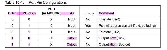
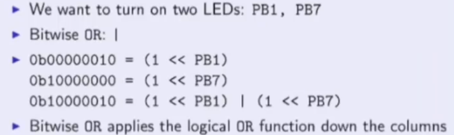
- ‘Peripherals’ are controlled by ‘Registers’ (Special Function Registers)…configured as 8 single-bit switches arranged in a linear sequence. Switching each of the 8-bits On/Off in a specific pattern will define the function of that ‘Register’. In GCC…’Register’ switches are represented ‘visually’…ex: 0B00000010 means that the 2nd switch of the register (Pin 1…counted from right to left starting with zero) is ON.
- I/O pins are configured (as Input or Output) with Data Direction Register (DDR)
- Bitwise method (utilizing built in macros) is used to abstract binary syntax to make the code more streamlined
Diving into the Datasheet
Armed with an overview of the AVR Microcontroller, I was ready to try to tackle reading the Atmel ATtiny Datasheet once again. And this time it goes a bit smoother. Matrix code is beginning to resolve itself into sensible words and understandings.
Some key takeaways…
- The Datasheet is a reference manual…not a novel…cannot be read front to back.
- In my opinion, the best place to start is at the back, starting from page 224…where (inexplicably) the ‘Table of Contents’ is located. These pages provides a structural overview of how this reference manual is organized. Tip: If you click on the page number in the Table of Contents, it will bring you to that page.
- After the big picture is understood, reading xxx to get an understanding of the unique features of the
- The most useful general reference pages:
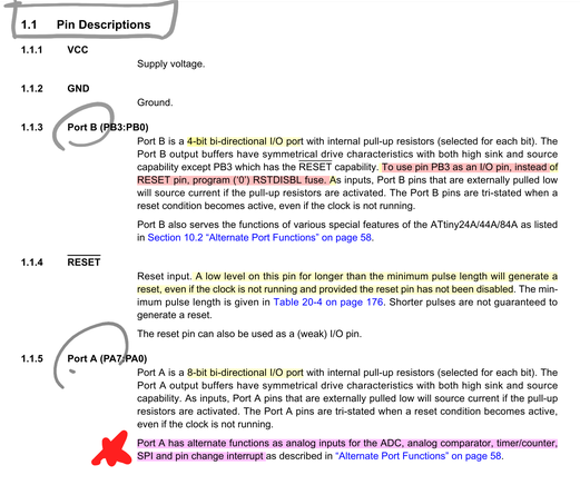
- Page 1: Features
- Page 2-3: Pin Diagram & Pin Descriptions
- Page 4: Block Diagram of AVR Chipset
- Page 7: Block Diagram of AVR architecture
- Page 9: Diagram & Description of AVR CPU General Purpose Working Registers
- Page 215: Register Summary
A handy converstion chart to change Arduino Pin designations to C Code designations…
- From Page 7 onwards…the Datasheet describes each major component groups on the chip in detail. As Elliott Williams suggests…read the beginning and end of each chapter…to get an overview then how to configure registers.
- The Datasheet provides very useful code examples throughout.
- The AVR chip has 8 built in ‘Peripherals’ to handle some tasks and free up the CPU for calculation work
Beyond Blink…Making Practical Use of the Datasheet
While scanning YouTube for videos relevant to this week’s subject matter, deciding which IDE platform I would focus on, I came across this video by Joop Brokking called “Why I’m Switching from the Awesome Aruduio IDE to Atmel Studio” here.
What made this video interesting to me was that Joop showed in concrete terms why GCC code in the Atmel Studio IDE was superior to code generated by the Arduino IDE. Specifically, Joop wrote a program to send a 5v pulse to the Microcontroller and demonstrated that Arduino presents a much less clean end signal (measured by a digital oscilloscope) than C…because of all the extra noise generating code that Arduino’s programs have by default. I thought, by recreating his demonstration…I would learn something about the differences in code between Arduino Sketch and Atmel Studio C. And…as a bonus…I could use this opportunity to use the Multimeter digital oscilloscope again…to get more experience on them.
Replicating Joop Brokking’s demonstration
So I replicated Joop’s 5V Pulse Generator code to produce a 50 millisecond delay in Arduino and uploaded it to the EchoHelloBoard.
void setup() {
  // put your setup code here, to run once:
  //pinMode(LED,OUTPUT);
  DDRA |= 0B10000000; //sets ATtiny pin 7 as output
}

void loop() {
  // generate a 50microsecond pulse
  // digitalWrite(LED,HIGH);
  PORTA |= 0B10000000; //sets pin ON
  delayMicroseconds(50); //pauses for 50 microseconds
  //digitalWrite(LED,LOW);
  PORTA &= 0B01111111; //sets pin OFF
  delayMicroseconds(50); //pauses for 50 microseconds
}
With the code successfully uploaded to the EchoHelloBoard, I first used a Multimeter to check voltages. First, I checked the voltage entering the board by measuring at the FTDI connector pins. The incoming voltage read…5.15v.
Then I measured the voltage at the pin and read 2.49v. I then switched to the Digital Oscilloscope to take the same readings and got 5.14v and 2.49v, respectively.
On the Oscilloscope, one can easy see the pulse width expansion…
The 5V Pulse Width program runs OK on the EchoHelloBoard via the Arduitno IDE.
video for 5v pulse using Arduino IDEs
- First observation…I was not getting a clean 5.0v signals.
- Second observation…the signal was jumping from around 5.0v to something higher…indicating that a greater delay in timing as causing a greater pulse width.
- Joop was right…something in the Arduino code was causing a distortion to the desired signal generation. Arduino’s support pages describes “the approximation is due to execution of the other instructions in the code”
With initial measurements done, I followed Joop’s procedure and replaced Arduino code with some C code. Arduino’s ‘digitalWrite’ function was adding 3.5 microseconds to the signal delay…added to 50microseconds delay time.The ATtiny is able to switch a pin ON and OFF within 2 clock cycles or around 125 nanoseconds…28x faster than Arduino’s ‘digital write). Code adjusted and board signals remeasured.
-
First observation…killing the extra processes had the desired effect of creating a cleaner signal closer to the desired 5.0v.
-
I then modified Arduino code, swapping out ‘digitalWrite’ commands for C code and Bitwise versions using Binary designations. I referred back to the Datasheet for Pin and Port names and for PORT register configuration specifications.
Code Versions: Blink Programm
- Arduino Sketch
- Binary
- Bitwise
// blink - Arduino Sketch

/*
  Blink

  Turns an LED on for one second, then off for one second, repeatedly.

  Most Arduinos have an on-board LED you can control. On the UNO, MEGA and ZERO
  it is attached to digital pin 13, on MKR1000 on pin 6. LED_BUILTIN is set to
  the correct LED pin independent of which board is used.
  If you want to know what pin the on-board LED is connected to on your Arduino
  model, check the Technical Specs of your board at:
  https://www.arduino.cc/en/Main/Products

  modified 8 May 2014
  by Scott Fitzgerald
  modified 2 Sep 2016
  by Arturo Guadalupi
  modified 8 Sep 2016
  by Colby Newman

  This example code is in the public domain.

  http://www.arduino.cc/en/Tutorial/Blink
*/

// the setup function runs once when you press reset or power the board
const int LED = 7;

void setup() {
  // initialize digital pin 6 as an output.
  pinMode(LED, OUTPUT);
}

// the loop function runs over and over again forever
void loop() {
  digitalWrite(LED, HIGH);   // turn the LED on (HIGH is the voltage level)
  delay(300);                       // wait for a second
  digitalWrite(LED, LOW);    // turn the LED off by making the voltage LOW
  delay(50);                       // wait for a second
  digitalWrite(LED, HIGH);   // turn the LED on (HIGH is the voltage level)
  delay(300);                       // wait for a second
  digitalWrite(LED, LOW);    // turn the LED off by making the voltage LOW
  delay(50);                       // wait for a second
}
//Blink - Binary

/*
 * BlinkLEDAtmelBinaryCode.c
 *
 * Created: 3/18/2019 12:21:58 AM
 * Author : Rico K. after Elliott Williams
 */

void setup() {
  DDRA |= 0B10000000; //sets ATtiny pin 7 as output
}

void loop() {
  // generate a 50microsecond pulse

  PORTA |= 0B10000000;      //sets pin ON
  delayMicroseconds(50);    //pauses for 50 microseconds

  PORTA &= 0B01111111;      //sets pin OFF
  delayMicroseconds(50);    //pauses for 50 microseconds
}
// Blink - BitWise & BitShift

/*
 * BlinkLEDAtmelBitShiftCode.c
 *
 * Created: 3/18/2019 12:21:58 AM
 * Author : Rico K. after Elliott Williams
 */

#define F_CPU 16000000UL

#include <avr/io.h>
#include <util/delay.h>

#define LED PA7
#define LED_PORT    PORTA
#define  LED_DDR    DDRA

int main(void){
    LED_DDR |= (1 << LED);      //enable Output on LED

    while (1){

    LED_PORT |= (1 << LED);     //sets LED to HIGH, by setting bit with OR
    _delay_ms(1000);            //delay 1sec

    LED_PORT &= ~(1 << LED);    //sets LED to LOW, by clearing bit with AND and NOT
    _delay_ms(1000);            //delay 1sec
    }
}
Links
Links to other instances where Datasheet referencing was important to project work…
Week11…Analog-to-Digital Converter and the PhotoTransistor
Week12…Pulse Width Modulation usage to control LED and Servos
Appendix:
AVR: Alf & Vegard’s RISC processor
- Modified Harvard architecture 8-bit RISC…‘On-chip flash’ memory for program storage…as opposed to ‘one-time programmable’ ROM, EPROM or EEPROM used by other microcontrollers
- Used in ‘Embedded Systems’…real time, embedded as part of a complete device including hardware and mechanical parts
- Tiny series…0.5-32KB program memory, 6-32 pin package, limited peripheral set
- Flash, EEPROM and SRAM integrated onto a single chip…no need for external memory…some have parallel external bus option for adding memory.
- Program instruction stored in non-volatile flash memory
- The MCUs are 8-bit…but each instruction takes one or two 16-bit words
- The size of the programming memory in the name of the chip…ATtiny44 has 44KB of flash memory
- No provision for off-chip program memory…all code executed by the AVR core must reside in the on-chip flash
- Internal registers…32 single byte registers, classified as 8-bit RISC devices
- SRAM starts after the register section
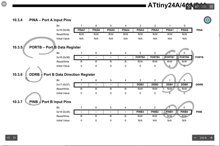
- GPIO port on a tiny controlled by 3 8-bit registers: DDRx (Data Direction Register), PORTx (Output port register…sets output value on pins configured as Outputs; enables/disables pull-up registers on pins configured as Inputs), and PINx (Input register, used to read an input signal…on some chips can be used for Pin Toggling…writing logic 1 ot a PINx toggles corresponding bit in PORTx, irrespective of the setting of the DDRx bit)…x is the port identifier)
- EEPROM for semi-permanent data storage…can only be accessed an external peripheral device is, using a special pointer registers and read/write instructions…makes EEPROM slower than other internal RAM. Limited 100k write cycles
- AVRs have 2-stage, single-level pipeline design…the next machine instruction fetched as the current is executing. Most instructions only take 1 or 2 clock cycles…AVR are fast 8-bit controllers
- AVR designed with efficient execution of compiled C code in mind
Tool Chain
A set of tools used in sequence (the output of one comprises the input of the next) that is used to perform a complex software development task…compiler, libraries, debugger
- GCC compiler…targeting AVR
- Binary Tools (linking, assembly, conversions)
- avr-libc library
- avrdude for programming the board
GCC Tool Chain
GNU Compiler Collection…a set of compilers for different languages from GNU. Front ends for various languages (C, C++, etc.) as well as libraries for those languages. Back-ends that generate assembly code for many processors and OS. More on GCC here
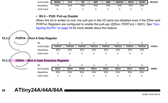
DDR
DDR is used for setting the direction (INPUT or OUTPUT) of GPIO pins. DDRB, for example, is the Data Direction register for PORT “B”.
-
If you set this register to 0xFF (by running DDRB |= 0xFF ), all ports or pins in the “B” I/O port act as outputs.
-
If you set DDRB to 0x00 (it’s initialized to 0x00 by default), then all ports or pins in the “B” I/O port act as inputs.
After setting the DDRB register…
- If set as Output, individual Pins of PORTB can be set to HIGH or LOW voltages.
- To output a low voltage -> PORTB &= ~(1<<PB0).
-
This method clears or sets only the PORTs that we explicitly want to manipulate.
-
If set as an input, then you can read a certain Pin/Port(s) voltage state (HIGH/LOW).
- if ( PINB & 0x01 == 0x00) means PB0 is HIGH
- if ( PINB & 0x03 == 0x00) means both PB0 and PB1 are HIGH triggered.
- If its configured as an input and if you set PORTB register bits to 1, then the corresponding pin/port’s input pull-up resistor will be enabled.
Bitwise Operators
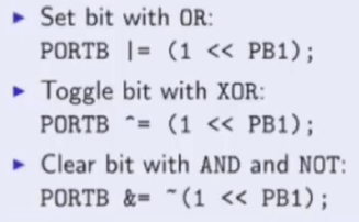
|= (Bitwise OR)…the bitwise OR of two bits is 1 if either or both of the input bits is 1, otherwise it is 0.
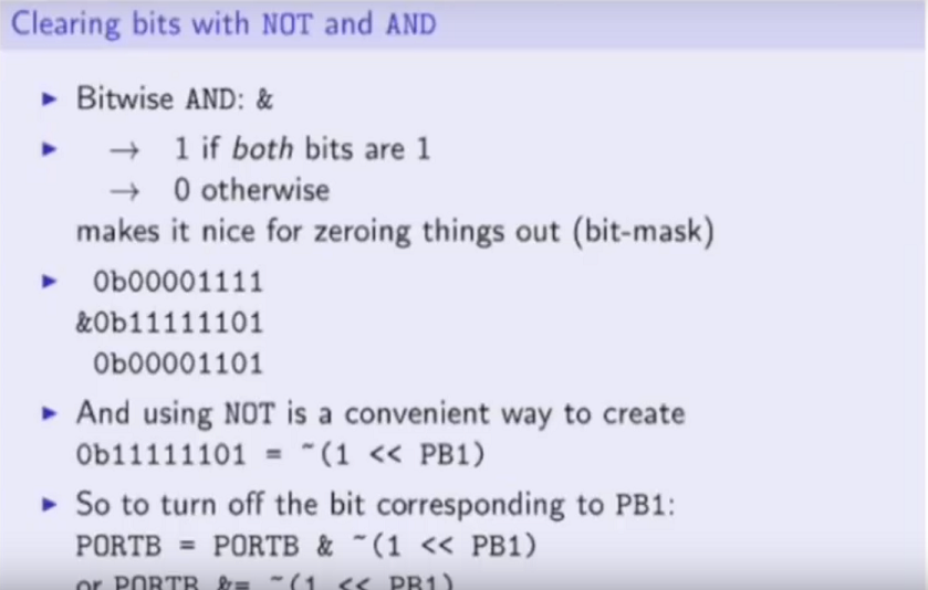
&= (Bitwise AND)…if both input bits are 1, the resulting output is 1, otherwise the output is 0.
^= (Bitwise XOR)…similar to bitwise OR except that it evaluates to 1 for a given position when exactly one of the input bits for that position is 1. If both are 0 or 1, the XOR operator evaluates to 0.
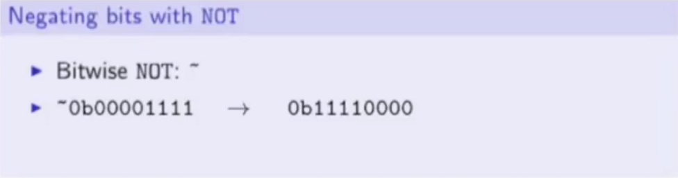
~= (Bitwise NOT)…bitwise NOT changes each bit to its opposite: 0 becomes 1, and 1 becomes 0)
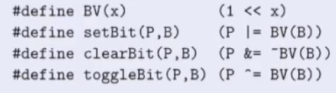
There is even code for predefined macros for these Bitwise operations…
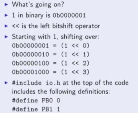
Bitshift
Bootloader:
- A piece of code that runs before any operating system is running…used to boot other operating systems
- First software to run after startup
- Highly processor and board specific
EEPROM: Electrically Erasable Programmable Read-Only Memory
- A read-only memory whose contents can be erased and reprogrammed using a pulsed voltage
- A type of non-volatile memory used in computers, integrated in microcontrollers
Fuses
- Set it once, but must do it right
- 3 bytes of permanent (active after power out) storage called ‘Fuses’
- Fuses determine how the chip will act…if it has a bootloader, what speed, what voltage to run, etc.
- Fuses are resettable…doesn’t have anything to do with protection from overpowering
-
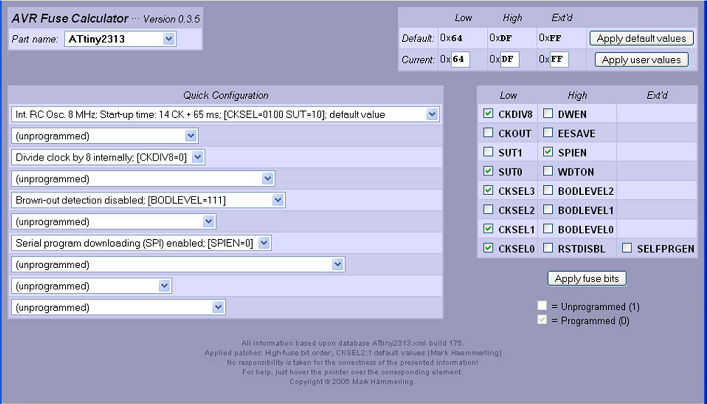
Look at fuses via a Fuse Calculator here
-
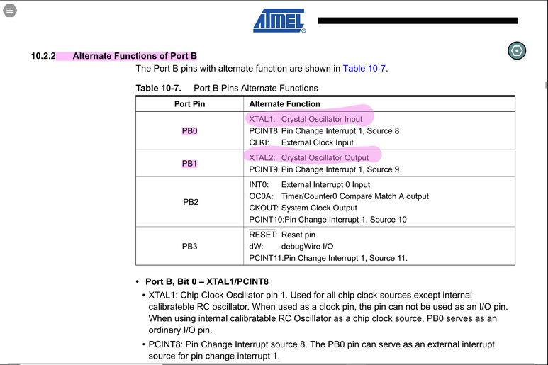
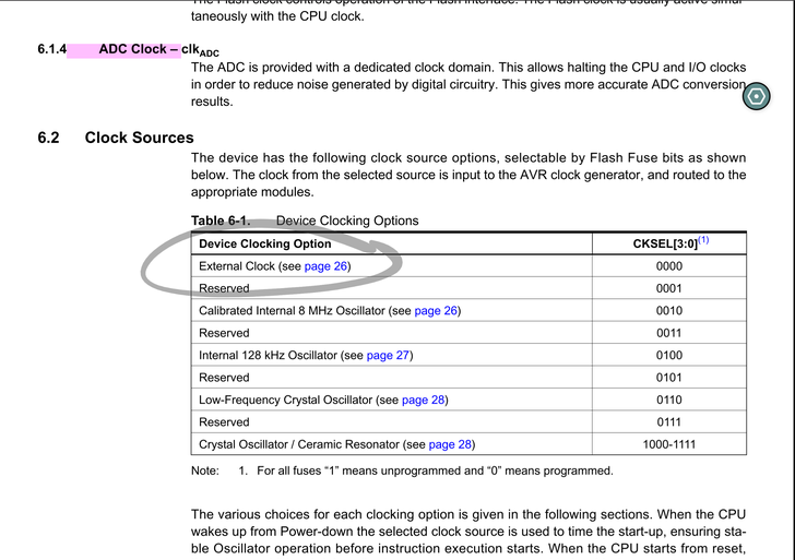
Clock Selection: detm how a chip is clocked. In general one assembly code instruction is run every clock cycle. ‘clock source’ and ‘clock startup’ are the key settings. ‘clock source’ can be external clock/crystal or one of several internal clocks (running at different frequencies). The ‘clock setup’ can be one of 3 modes…14ck+0 ms, 14CK+4ms, 14CK+65ms. ‘External Clock’ means a square wave is being input into the ‘clock-in’ pin…this is rare unless you have a clock generating chip (don’t use unless you really want to). ‘Internal Clock’ means a little oscillator inside the chip (not precise but good enough for most projects)…varies with temperature and power supply voltage (8MHz, 4MHz, 128KHz (for low power applications where running chip slowly needed to conserve power) are options). Internal oscillator means pin freed up for other uses. ‘External Crystal’…if a special clock rate (like 3.58MHz or 12MHz) or high precision clock unaffected by temperature matters. ‘Startup Time’ is just how long the clock source needs to calm down from when power is first applied…go with longest setting 14CK+65ms typically, unless specific requirements for shorter startup time. From factory…Internal 8MHz clock with 14CK+65ms startup.
- Clock Output: …on PortD2, whatever the clock input is a square wave of the same frequency will appear on pin D2…useful if you’re debugging the clock rate or if you want to use the clock to dive another chip. This is turned OFF from the factory.
- Clock Divide: This fuse causes the chip to divide the clock rate by 8 (an Internal 8MHz clock with this fuse set runs at 1MHz). Turned ON from the factory.
- Reset Disable: Turns the RESET pin into a normal pin. Turned ON, the chip cannot be programmed using ISP anymore. Don’t use this fuse unless you intend to. Turned OFF from the factory.
- Brown Out Detect (BOD): Sets what voltage to turn the Brownout (voltage drop affecting reliable running of the chip…erasing or overwriting RAM and EEPROM, running random piece of programs) protection circuitry on. Will cause chip to turn off until voltage returns…resets and starts over. No BOD from factory, recommend setting it…especially if there is a bootloader or storing data in EEPROM, the BOD setting is a must!