When is the last time you weight yourself? Whether you cannot locate the scale in the bathroom, or forgot about using it, or just have no space for a scale, a mon only weight himself every two months.
INVESTIGATION
Where is the one place we go at least once a day?
SOLUTION
An integrated toilet seat/ toilet mat seems the ideal solution, and idea that was suggested 7 years ago, but not yet commercialised
FabLab 2017 Assignements
Everyweek a new challenge
Week 1
01. PRINCIPLES & PRACTICES, PROJECT MANAGEMENT
Week 2
02. COMPUTER-AIDED DESIGN (Feb 1)
Week 3
03. COMPUTER-CONTROLLED CUTTING (Feb 8)
Week 4
04. ELECTRONICS PRODUCTION (Feb 15)
Week 5
3D scanning and printing (Feb 22)
Week 6
06. electronics design (Mar 1)
Week 7
07. COMPUTER-CONTROLLED MACHINING
Week 8
08. EMBEDDED PROGRAMMING
Week 9 & 11
09. Mechanical Design & 10. Machine Design
Week 10
10. OUTPUT DEVICES
Week 12
12. MOLDING AND CASTING
Week 13
13. INPUT DEVICES
Week 14
14. COMPOSITES
Week 15
15. NETWORKING AND COMMUNICATIONS
Week 16
16. INTERFACE AND APPLICATION PROGRAMMING
Week 17
17. APPLICATIONS AND IMPLICATIONS
Week 18
18. INVENTION, INTELLECTUAL PROPERTY, AND INCOME
Week 19
19. PROJECT DEVELOPMENT
JC THUAN
Ideas and words do not count, only actions matter
1986-Paris
My Haircut
Creative was not
2016-Brussels
My encounter with the maker movement
I accidently came accross the microfactory in brussels, a pool of friendly and super energetic maker group in brussels, led by a super motivated person called Gilles. I loved it ! and realised I wanted to develop my skills in this are.
Jan 2017-Barcelona
The Fab Academy 2017
It was time to take a sabatical from work! and study again, with the clear objective to develop and launch some of the ideas i had in my head
June 2017
The future
A cristall ball would be a nice to have, but even better (more fun) tolets code, 3D design, prototype, refine this future
Next
Coming
Soon!
SIDE PROJECTS
There is fablab and there are those odd projects I enjoy developing.
NOCCITO Urban poetry
Flowers + Frames spread out in the city. I see it as something poetic, short-living, and wonderfully satisfying
SuperBurgerBox
One hand only to eat your burger menu
Smart Invest Your Small Changes
How to make the best use of the leftover currencies you have when travelling abroad
For the past 3 years as part of my job I have been debugging html pages or email when there was a glitch, or some modifications were needed, so I was somehow familiar with html language. However I never built a website in html myself so I found it an interesting excercise. It was also my first time using terminal command & github.
Option 1: Creating the website from scratch, writing the html directly on html page.
Option 2: Download & adapt an existing web template
Benefits of using Web Template
Web templates are great when you have limited experience in html, you benefit from best practices and latest trends in web user experience & user experience (responsive, animations, user path). It is also a source of inspiration, and very importantly it ensures your website has an important degree of consistency in terms of designs from the start.
Drawback of using WebTemplate
What i am now finding is that you spend a lot of time understanding how the website and the corresponding CSS have been developped if ever you need to make a change to the webtemplate. Overall, I would say if you are going to exactly use the section (DIV) and fonts and organisation from the template, template are greats. However if you think you need to make some customisation, I would have preferred to build the website from scratch directly. I think it would actually save time at the end.
Selection the template from bootstrap called "Agency"
Start Bootstrap is a collection of free to download Bootstrap themes and templates. Our themes are open source and you can use them for any purpose, even comercially! I reviewed the various templates and seleted the agency template because I liked the one page template and the way the information were organised on the page. The idea was to use the portfolio section for assignement.
You will download a number of files that need to be kept in the same foler
Open the index html file with bracket
Modify the html code in bracket
You can use additional font by dowloading them from google link here
Save the hmtl
I also modified the CSS & save it to reduce file size
CSS Stylesheet
Stylesheet are a great way to ensure consistency in my website design. I have created a couple of additional class in the css sheet to manage Subtitles & section to display code
H4 title
H5 title
Line of code
Image storage
Optimising image space
We need to optimise image size for 2 reasons: we are limited in storage space on the git hub, and the lighter the image/the webpages the quicker it loads. Therefore I did two things. First I optimised pictures in photoshop (save for web as jpeg quality between 20 and 30 depending on how it looks).
Storing images on a external server
Secondly I searched what was the best data storage solution for publishing images on the web. The top recommendation was to use of S3 amazon server to store large images. I therefore used S3 Amazon for storing my images. I need to explore Amazon S3 as it looks like a powerful solution for web hosting. However I was told i might to pay after a year of using Amazon S3, therefore i looked for an alternative solution. I have since transitioned the storage of images to a my own newly created git repository. I have also tried Google drive but it takes longer to display the image on the web (5 steps needed: go to google drive, select the image, make it shareable by right clicking, copy the URL provided, and modified it so it have the following syntax https://drive.google.com/uc?export=view&id=Image-ID".)
web analytics & Search Engine Optimisation
If you create a website you might as well want to promote it. One way to promote is by optimising the presence of your website on search engines. There are several ways to do it and a good start is tol follow the recommendation on How to Get Your New Website or Blog Discovered:.
Create a Sitemap
Submit Sitemap to Google Webmaster Tools
Install Google Analytics
Submit Website URL to Search Engines
Create or Update Social Profiles
Share Your New Website Link
Out of those options, I install google analytics and submitted the Website URL to google. To instally google analytics, visit Google Analytics, sign up with your google id. Go to Admin (bottom left of the home screen) & create a new account.
In the Property section, go to tracking info. You will be able to copy the JavaScript Tracking code lines
Back onto your html page, copy this code at the end of the header section of your webpage. Note you will have to repeat the opeation for each webpage of your site, unless you place directly the code into a webpage template, that is being used by all pages of your site
It was interesting to track the visits per month. However to be more accurate I should exclude my IP address from the tracking.
PRODUCING THE DESIGN WITH THE LASER CUTTING MACHINE
Publishing the site to the web
Setting up the git
"Git is a distributed version control system, which means you can work locally but you can also share or “push” your changes to other servers. Before you can push your changes to a GitLab server you need a secure communication channel for sharing information. GitLab uses Public-key or asymmetric cryptography which encrypts a communication channel by locking it with your “private key”." source here
Login/create account to: fablabs.io
Go to http://git.fabacademy.org/ and login with your fablabs.io credentials. Once you have your username of fablabs.io
Add a ssh-key to your account.
What started as a joke between friends
Generate a SSH Key
A SSHKey is used to have a secure communication between my computer and the Gitlab
In terminal: cat ~/.ssh/id_rsa.pub
To generate a new SSH key, use the following command: ssh-keygen -t rsa -C “$your_email”
Use the command below to show your public key:cat ~/.ssh/id_rsa.pub
Please copy the complete key starting with ssh-rsa and ending with your username and host. Mac: pbcopy ~/.ssh/id_rsa.pub
Download and install: git
Transfering my files onto the web
Open Terminal in MAC
Using the "cd" command to locate the folder where my files (html pages, css files, javascript,....) are saved on my laptop. I use the "ls" command to ensure I am in the right folder. cd Desktop/Fablab/fablabbcn/students/48
Pull the archive to my computer. Here I am downloading all the files onto my laptopcd pull
To know what are the changes since last pullgit status
git add.
git commit -m "commit message"
git push
Project idea
What started as a joke between friends, became a more impregnated idea in my brain. Not only have a toilet seat to weight you was a fun idea to put in practice fab academy learnings, but i also realised there was an actual need for it.
Two reasons pushed in that direction.
In certain large metropolitan cities housing space is very limited. In paris, where i come from, you often find 20 sqm studio, where the toilet/bathroom is very small, and where its is almost impossible to have a scale in the bathroom. A integrated toilet seat scale would be a solution
Man dont weight themselves much. Very often it is not about being agains it, it is just about not thinking about it, not taking the scale out of the cupboard,etc.... The product would encourage the control of your weight.
I then started to look at 3 possible options for the toilet seat scale:
Week 2
02. COMPUTER-AIDED DESIGN
Deliverables
Comments
Try as many 2D/3D softwares you can.
3 softwares tried to recreate a bolt
Modelled experimental objects/part of a possible project in 2D and 3D software.
See Toilet Design in 3D
Shown how you did it with words/images/screenshots
This week was challenging for me ! 3Design? Wow !
NEWBIE zone: As it was all new to me I tried to match the various tools I got exposed (listed above) to vs my projects needs and time. I was impressed by SolidWorks as it looks like the ideal tool for any engineering design. Blender looks extremely powerful, and I enjoyed using it after a intial shock when discoverint the interface. Grasshoper programactic approach was very interesting, in particular in terms of machine shaped design, and the ability to collect data from external source (I am thinking Arduino sensors), to mofidy the 3D design based on this.
How to select the right 3D Software for my needs
PROJECT REQUIREMENTS VS EASE OF USE VS COST.
Based on the requirements of my project (3D Toilet and Toilet Seat containing electronics) and limited (none) knowlegde of 3D design, the fact SOLID WORKS is for Windows only, I had to limit myself to 3 tools for a more detailed trials of the tools.
The Tools selected to start with tutorials were Onshape (Free/Limited online 3D), Rhyno (Trial version), Fusion 3D (open source). To facilitate my selection I run 2 tests (or challenges).
THE BOLT 3D TEST
The idea was to test multiple 3D softwares (Onshape, Fusion 360 and Rhynoceros), making use of tutorials, to recreate a bolt in each tool, and see the pro and cons for a newbie
RESULT BOLT 3D TEST
ONSHAPE was probably the easiest and quickest tool out of the 3 to create the tool. Menu options is limited and clearly explained which makes it an ideal tool for beginner. Onshape is very similar to SolidWorks and include feature I really like (constraints for lines, object in relation to each other in the assembly mode). Yet there is an issue of performance with Onshape. As it is online tool, it can slow down from time to time.
RHYNO: surpringly not the easiest tool to create a bolt. The method is similar than Onshape but includes many more steps.
THE WASHROOM TOILET 3D TEST
As part of my final project I will need to create a 3D washoom and 3 seat cover.
RESULT WASHROOM 3D TEST
I initially leaned toward Onshape. Unfortunately Onshape still lacks some 3D features I would need for my project: The method to create sphere to be able to create a toilet bowl is cumbersome. Moreover esthetics of the bowl is very limited in Testing Onshape. Regarding Fusion 3D I unfortunately did not have the time to run the tests with this tool yet.
FINAL TESTS RESULT
I selected Rhino vs Onshape, for two reasons: First Onshape is limited in terms of stylish design. Secondly, I have to admit having some fellow tutors, studens with expertise with Rhino also helped my choice. However i give the possibility to switch to Fusion 360 once i complete the tests with this software
DELIVERABLES
Modelled experimental objects/part of a possible project in 2D and 3D software: See pictures above.
Shown how you did it. As I wanted to have a 3D toilet design with a certaine aesthetics, I opted out for Rhino. I got lucky and found a tutorial on how to make a toilet in a different software (MAYA), but that enable me to see each step of the process, starting with sphere, sphere cut, sphere split, extrusion of tube, joining of objects (water tank, toilet bowl, water evacuation tube), including filleting. I also follow a tuturial on cocoon sofa 3D for Rhyno design which helped with the toilet bowl shape. Finally some fellow students showed me two other methods in rhyno that did greatly improved the style of the water bowl.
Included your original design files. Download here Rhyno file. >>>
Try as many 2D/3D softwares you can: all 3D softwares listed above except Solidworks were tested to different degree
2D Design software
Photoshop
I started playing with photoshop after many years. I took this opportunity to create my first gif animation with the help of one more advanced classmate Wim Lanz. The GIF represents how I fell during the first week of the fab academy. It only starts on page load and is NOT on a loop. I realised the major drawback of gif was the size: 180k for a 300*400pixel animation with 4 frames. The can be downloaded here
Gif test>
Inskape/Illustrator
I tried both Illustrator and inskape. Although Illustrator has a better of reputation in terms of features, I found Inskape much easier to start with. In week 3 assignement I have design my sticker with Inskape
Week 3
03. COMPUTER-CONTROLLED CUTTING.
Deliverables
1. Design, make, a (1) parametric (2) press-fit construction kit which can be (3) assembled in multiple ways
I created an heart shaped structure.
2. Cut something on the vinylcutter
I made a sticker for both my laptop and t-shirt
3. Group assignment: Make lasercutter test part(s), varying cutting settings and slot dimensions
Again this was a very challenging and very interesting week that gave the chance to practice further more 3D design. It gave me the chance to see the physical outcode of 3D design. I really loved being able to design, produce, and install the sticker on my laptop. I was also very happy to use this week to design my own unique t-shirt models :)
01. Press-fit construction kit inspired by Valentine week
Inspiration
I went through an extensive brainstorming. Results: many ideas, many attempts. On the positive side I quickly realized when my idea was either not feasible, too complicated or time consuming.
Then I remembered Valentine day was coming soon, I also remembered my previous break ups, where my heart was shattered, and I decided to created a object representing each past relationship I got dumped, with the size and number of stabs in my heart varying from one relation to the other. Although this does not sound like a very positive project :), It is not as bad as it sounds and is to be seen more as visual parametric representation of past experiences.
I will try to do the same project with past positive experiences :)
A pametric design
In Fusion 360 I made 3 values parametrics (Fusion 360 is not the easiest to use in my opinion but the parametric fonction is easier than rhyno grasshoper).
Thickness of the materials (cardboard as default 3.5mm) but can be modified in the parametric sheet to change all openings.
Number of stabs the heart is containing (from 2 to as many as 8).
Width of the blade corresponding to the pain suffer.
- Improvement for next time: make the size of the heart corresponding to the importance of the relationship parametric as well.
Creating the 3D model in Fusion 360
ExactFlat Online: This is a separate plug in the 3D to 2D solution for Fusion 360. Unfortunately despite many attemps I never managed to make it work for my design to use it for laser cutting. Instead I saved each sketch as dxf directly in Fusion 360.
Rhyno Trial: I also made an attempt to design the same model in Rhynoceros. Unfortunately I did not manage to complete the task. This shows I need to undertand rhyno more
3. Group assignment: Make lasercutter test part(s), varying cutting settings and slot dimensions
I got the chance to the see the LASER CUT - Multicam 2000 in action which is an incredibly accurate laser cutter despite its large size. The way to operate it is different yet similar, so I took many notes. I also saw the LASER CUT - Epilog Legend we have at FabLab Barcelona in action. As it losts power through time, it is now mainly used for engraving.
As group we made some test with the corrugated materials we were going to use for our project. That showed us the kerf (explained below) for the machine, the settings needed for the material, and how this influenced our design when parts need to be inserted into each other.
Another method to find what the kerf is
To test the kerf I designed quickly a 10mm by 10mm square and Rhyno and lazer cut it. It is also a good way to test if the power/speed/resolution are adequate (not too much but sufficient enough) to cut through the materials. You then mesure the size of the square that was cut and see the difference in width (and divide by 2) to have the kerf. You can also find a more accurate method to measure it from James Williamson (that havent tried)- link here
Producing the design with the laser cutting machine
What you need to think about when design for lazer cut
My design comprises heart shapes that need to insert into each other to create a bigger shape. In addition, the "blades" also need to enter the "heart" shape.
When using a lazer, the lazer will burn a portion of the material it cuts through. The exact dimension depends on the machine, materias and settings. It is generally a bit less than 1mm for the corrugated material I am using here. However it is important to test it.
I am using the blade and handle of the dagger as pressfit fixations, as well as the heart shape itself.
Final Result
Learnings
Safety is paramount in laser cutting (air ventilation, always supervising the cut, and stopping if flames start to appear)
Adjusting the laser machine: Speed, Dpi, power were adjusted by the team the day before I used the laser cutting, so I had the details for lazer cutting cardboard. However when I tested the laser cutting on the same cardboard materials before cutting, we found the the cut was not so clean as the day before.The Fablab manager investigated and found out because of the extensive testing the day before, the lenses & mirror of the laser needed cleaning.Safety is paramount in laser cutting (
Learning: rather than increasing power and risks potential fire, best to check the lenses and mirror first if settings are what they should be
02. Cut something on the vinyl cutter
Inspiration
Combining my French and Vietnamese origins I wanted to create a logo that represented the both side of my origins.
how did I design it ?
I designed in Inskape (which I am starting to like :) a sticker design for my latop.
First i searched for png pictures on the web I could use as a starting poit before modifying it. For instance the hat below is a mix of a chinse hat and a french baguette.
Steps
Import the png file in your inskape design
Import the png file in your inskape design
click on Path tab, Trace bitmap
I used the Path Combine, Union, Division, etc... to combine shapes together
I then edit nodes by moving them around. If necessary I added nodes to be able to modify the design to my wish. wiki tutorial on nodes editing.
After using the logo i created for stickers, I decided to do t-shirts as well. For this I used a piece of 3mm width wood that I lazer cut.
Using the lazer cutter
I booked the SPIRIT GE lazer machine for this job
This lazer use Rhynoceros for cutting
I imported my design in Rhynoceros
I found a recycled 3mm mdf material type in the storage
I check the settings for mdf based on various test previously performed and noted down the settings (speed power, ppe)
I sent the design to the cutter
In settings, for the black line corresponding to my design, I selected Speed (how fast will the lazer cut)=12, Power (power of the lazer)=100 percent, PPE=4000 (Resolution/Frequency of the lazer)
VERY IMPORTANT: Ensure the ventilation of the lazer machine is on and working before starting a lazer job
I made a test for a 10mm square. The lazer cut through and there were no flammes or too much smoke
I set the lazer to start from top left corner of my design using the control on the machine & set it up as 0,0,0
I press start on the cuter. 5 minutes later the cut was performed
Note it is vital to stay while the lazer is cutting to avoid any problems with the machine (be ready to press the pause button on the machine)
Week 4
04. Electronic Production.
Deliverables
1. Shown how you made and programmed the board.
2. Explained any problems and how you fixed them.
There were plenty :) and I found the solution after using google advanced search to find out if someone else in the previous year experienced the same issue.
This was a completely new field for me. Surprinsingly I never heard in m life about a micro-controller until this week, and the different language to program a board. What was also challenging was soldering electronic components that seemed so small. The good news is I have used a few times the skills learned during this week to fix my mac charger and my portable speakers.
Links
"How to make computer" class given by Guillem Camprodon" gives a really good understanding of why a micro-controller is needed to program a board
First some explanation on what is a FabISP.
"The FabISP is an in-system programmer for AVR microcontrollers, designed for production within a FabLab. It allows you to program the microcontrollers on other boards you make" (More info).
1. Producing the design of the FabISP Board
For this assignment we are starting from an existing board design. I started by downloading the PCB Traces & ithe outline from Neil design.
2. From a png to a Gcode file that can be read by the milling machine.
Rolland Milling machine use Gcode to drill the copper out of the board so you end up with the desired board. To do so we need a way to convert traces from a png file to Gcode file. For this we have available a platform called Fabmodules that contains a tool to do the conversion. Note it important the png are in black and white so fabmodules can read it.
In Process, select PCB traces (1/64) for drilling electrical connections on the board. (1/64) corresponds to the size of th mill bit.
In Process, select PCB outline (1/32) for cutting the contour of the board.
Add the settings corresponding to the machine you use
Click on Calculate to simulate the milling
Review what the machine will do & adjust the settings if necessary, in particular Number of offsets
When you are satisfy, click on save to save the file
3. Cutting the FabISP Board
I did the set up & cut on the machine Roland Modela MDX-20. Setting the the x,y origin on the machine was the easy part. Setting the Z is a bit more delicate, but with tips from the fablab coordinator this was correctly done so the drill is in direct contact with board. A good tip is to go as further close to the board as your human eye can see and then release the drill by untighing it so it "falls" onto the surface of the board.
For the board trace I used a 1/64 drill, and the a 1/34 to cut the contour.
Note: it is key to set the X/Y as origin when drilling traces and we would use it to drill the contour.
3. Soldering the components on the FabiSP board and programming the board
Soldering & troubleshooting day 1
After gathering all the components I dived into soldering without trying on an used board. And that what was not a good idea.
Next, I checked the connectivity of the circuit hoping the AVR micro controller would indicate the electrical connetions are ok (there are no short circuit) by displaying a green light: That was not the case at first.
This gave the opportunity to really learn about the role of each of the component (resistors, jumpers, diodes, …) and how the current was flowing from one to the other.
Xavi, one of the instructor kindly taught me how to use the voltmeter to check each soldering points.
At the end of the day I soldered again most of my components.
Checking the AVR micro controllder is working correctly: after resoldering all components again and testing all connections we could not figure out why the AVR was still producing an incorrect connection signal (red light). We discovered the cable of the AVR was faulty all this time, after running the test with another controller.
All was now for the best, but then I accidently connected the usb pin incorrectly to the board burning out some of the components (I could hear the components burning out). The origin was because I connected the VCC of the to GROUND
I decided it was best to restart reprinting the board and soldering the components again.
Fortunately while picking the components I made two sets in case I needed to remake the board.
Soldering and troubleshooting Day 2
Day 2: I made another board and soldered the components. I checked each solder joint under the microscope to determine any weaknesses or solder shorts.
I checked to make sure each component matched the diagram I soldered.
I made sure the diodes and leds were correctly positioned directionally on the board.
I programmed the board quickly successfully I thought following the instructions
The ISPFABLab board not showing on the USB port of my laptop. I reprogrammed the board three times. Each time I did not get an error message.
Xavi one of the instructors used multiple computers, USB ports, a fresh Arduino install and Ubuntu to see if we could recognize the board on the USB port. But to no success.
It was recommended I checked previous year students webpages to see if someone faced the same issue.
I did not want to check all website so I used google advanced search to only search on the archive.fabacademy website.
I found two possible solutions. Solution 1 was to remove the jumpers before programming. It dit not work for me
Solution 2 was then tried: replacing the diodes that might have been burned during the soldering process while still showing (incorrectly) a correct connection (greenLight)
To my greatest relief solution 2 worked and after reprogramming the board again I could finally see it in my USB port
Follow the installation instructions for your operating system. Link here
In my Mac Terminal
cd Desktop/fabISP_mac.0.8.2_firmware
Type Make Clean
Type make hex
Next to program the board to be an ISP.
Type make program
After programming the board
After You Have Programmed the Board
Source of the image=http://archive.fabacademy.org/archives/2016/doc/programming_FabISP.html#mac
AVRISP mkII WHAT IS AVR MICROCONTROLLER?
Week 5
3D scanning and Printing.
Deliverables
Group Assignement: test the design rules for your printer(s)
Individual Assignment (1) Design and 3D print an object (small, few cm) that could not be made subtractivel
Individual Assignment (2) 3D scan an object (and optionally print it) (extra credit: make your own scanner)
In June 2017, the harddrive of my mac crashed. No data could be saved. The icloud back up was not set up correctly and was only backing up photos, and not files, amongst them a large share of my design files.
Feedback
This was a very exciting week for me. First, I had no idea 3D scanner like the Kinect could be accessed so easily, and that they worked so well. 3D scaning a person face was truly bewildering to me. Designing & 3D printing my own object (a small frame with a flower pot) was an objective of mine I had doing the fablab, so I was happy to make it happen. This also showed me the constraints that exist when design 3D object. I had to play with the thickness of the contour of the object & the support for printing to manage a successful 3D print.
Group assignment: Testing the design rules for your printer.
No 3D machine is the same. Some parts be the same — but the calibration and alignment of these vital parts can be off by just a fraction of a millimeter, and in turn cause issues with print, according to the online magazine 3Dprint. To overcome this, we must test the printer (known as calibrating process) to see how each part of the printer is performing. All those factors and test conditions can be found here.
Fortunately a person called ville with mutliple years of experience int he 3D industry, created one 3D project that helps to perform all the necessary test in one go, rather than multiple independent test. The file is available free of charge from Thingiverse and pictures from thingiverse can be seen below
This is the test we did as agroup. We first printed a copy of Ville model with black PLA filament, then with white PLA filement to better see the contrast. Both test below were run with the REPRAP. >Full results of the various test conducted can be found in here
What are the factors to play with when 3D printing
Choice of the 3D printer: the quality/time to print varies greatly between printers
Layer height - this will determine the quality of our printing in height but also the speed (the lower the layer height the longer it will take to print)
Choice of filament: PLA, ABS
Percentage of infill - Its a factor that plays with the strengh of your model. More infill - Stronger Object - More time to print.
Supports - this create some external supports in case we need them to hold any part that couldn't be printed without them
3D Scanning
3D Scanning with Kinect
I used the Kinect model 14 we had available from Xbox and the software Skannet to 3D scan. With the help of a classmate and after 3 attempt to get the motion and distance right I was able to collect a very detailed 3D of myself. I was seating on a rotating chair and the Kinect was hardly moving.
Kinect in action
This video shows me helping a classmate to 3D scan his upper body. He helped me do the the same. The video is from Wim Lanz website(link here)
Because we are using a free version of the software Skanet the number of meshes (and there the quality of the 3D scan) is limited. However there are a free useful too in Skanet that enables to remove any "noise" from the 3D scan that should not have been captured.
Meshmixer to create a shape with a meaning
This is the steps I followed to created this shape which is supposed to represent the idea of growing as a person, becoming more defined in a way
Free transform (white square) to reduce size
Edit > duplicate to create the duplicate object in a new layer
Edit > Free Transform to rotate Y, X the object
Select meshes, > Edit > Reduce the number of mesches percentage for the left part of each face, in order to have a growing pattern (representing the idea of becoming yourself)
Object > group Layers together.
CURA & 3D Printing
Addictive or Substractive manufacturing
"Additive Manufacturing is actually a synonym for 3D printing and/or any process by which 3D objects are constructed by successively depositing material in layers such that it becomes a predesigned shape. On the other hand Subtractive manufacturing is a process by which 3D objects are constructed by successively cutting material away from a solid block of material. Subtractive manufacturing can be done by manually cutting the material but is most typically done with a CNC Machine." according to creative mechanism (link)
Addictive (3D) for my design
In my case, because of the shape of the heads, where you would to drill from underneath, or from the side, to have the shape under the chin, additive manufacturing, or 3D printing is what I selected in that case.
The 3D print went well except one of the head fell because I did not use support, which I wanted to avoid. To solve this I used acetenone to melt the missing piece into the general print
Fina Result
Iphone App 3D scanning
I tried Nettelo to scan a body shape. As it is still cold we kept the cloth on, but overall the result was dissapointing
Creating an 3D Printed object
Design
In my free time I built flower frame by adding a flower pot into a wooden frame, using drills & nails. So I wanted to try 3D to see if I could produce the same
I first used Fusion 360 but I really struggled to create a nicely dented frame with volume, so I switched to Rhino, and with the precious help of Cytlali I could create exactly what I wanted
Cura Set up
Using cura to check what was the best way to position the object to print (faster, less support possible), it made me realise I had to modify my object to reduce as much as possible the support.
Avoid support if possible
As you will see in the pictures below, even after reducing the amount of support, I still needed to have some support in my print. What I did not know is how difficult it is to remove the support without damaging the print. I really undertand now why it is so important to take out as much as possible support.
Week 6
Electronics Design
Deliverables
Redraw the echo hello-world board and add (at least) a button and LED
This week was the chance for me to learn more about the Eeagle software.For this assignement I solely did manual routing in Eagle. It was particularly challenging to ensure all components are electrically connected with sufficient clearance between traces and I spent a lot of time redoing the routing. Secondly, I discovered the tricks of the Rolland milling machine: (1) The need for the support of the board to be absolutely flat, otherwise the board will be not be milled correctly. (2) The importance of setting the drill as close as possible to the surface of the board.
First we need to add the Fab Library to Eagle (download from Fab Academy archive here). It includes all the main electronic component we will be using for the Fab Academy assignement. You need to save it in the IBR folder in your eagle program where all the library are stored.
For the board design I used as a basis Neil board from the link here.
Adding a LED to the existing board
The assignement was to redraw the echo hello-world board and add (at least) a button and LED.
I decided to add a button and a LED. I learned we need to add a resistance when a adding a led to a circuit, to limit the current going through the LED to a safe value. (More info click here).
We need to know the value of the resistance to add. http://ledcalc.com/is a good tool to help us do so. Below you will see how I calculated the necessary resistance for my LED
Unfortunately, to be on the safer side, i added to the circuit a higher resistance 500ohms instead of the 180ohms recommended . As I will discover at the end of the assignement, this will make the LED light very weark
1. Design the board it the schematic mode in Eagle
Once Eagle was downloaded, and the fab library correctly imported, I added all the components to my schematic view, mainly adding the command line (ADD). I then went to Label & name each of the connection as per the graphic. Initially I started to manually connect each connection using the line symbol, but I swithched to the NET command i was recommended to connect components. The benefit is that you can connect two pins without the schematic being drown under too many lines.
After the schematic is completed change to board view: 2 options autorouter or manual router
After the shematic is completed (at least this is what I though) I switched to eagle board view where you have the possibility auto route manually the connections between the components based on the schematic completed earlier. I run the autorouter to give it a try but I could not picture/understand how the connection were made, so i prefered to make the connection manually.
Drawing the connection manually in Eagle
Tips using eagle
Go to options, grid, and reduce the grid size. I tried with .05 mm, it really helps drawing the trace in the board view.
Problems during the design of the board and how they were fixed
The DRC check see errors in your board design.
Problem solving the board in Eagle
After connecting the componenents on the board view, go to tools, DRC to ensure there are no errors in the board.
For a long time I could not understand my board errors until I went back to the schematic view where I realised I manually created a conneciton within the capacitor. OUGHR ! :)
Next step aClearance check
The clearance check is there to ensure that the milling machine drill wont trace over the components area on the board.
Clearance issue remains even after reducing the trace width in eagle. The concern with reducing trace width in eagle is the potential reduction in electricity conduction.
The board is finally ready in Eagle
I can now export the file as png, that I will open later in photophop
From Eagle to Photoshop to Fabmodule
I used photoshop to get the eagle board as trace and contour png images ready for milling. To do so I had to add an extra 2mm on each side of the board to create the contour. Note I followed instructions and used a high resolution of 500pi to get the best quality for milling. Note that there is often a translation issue of size between Eagle and Photoshop. To solve this I checked canva size in photoshop and reduce to 50% before exporting the Png files to be used in Fabmodules.
In FabModules
In Fab Modules, I created the rml files (traces and contour) for milling the board using a 1/64 mill bit for the traces and a 1/32 bit for the contour
Milling the electronic board
Set up ROllAND SRM-20
I used the X,Y,Z command in rolland to place the mill bit on the bottom left corner of the copper plate. Adjusting X&Y is easier than the Z (depth). Rolland let you adjust the speed in which you move the Z axis, enabling you to go really slowly when reaching clode to the cooper plate. A trick from the instructor Santi that I used is to go as close down as possible and then loosen the screw that holds the mill bit. The bit will "fall" onto the plate, and you can tightenn the mill bit again. It did work for me.
I used Fab Modules to get the files (traces with drill 1/64 (4 offsets) and contour with drill 1/32 (no offsets)) ready for the rolland SRM-20.
I had a few issues with the milling machine. At the end with the help of the instructor we had to set the Z axis by spinning the drill until it touches and the board and we could see the dust generated.
Once rolland machine was on I experienced 2 other issues, one for which I was to blame :). First I forgot to invert the image which meant the machine was milling the cooper out of where my componenents and connections were. Not very useful for an electronic board. Secondly, after i changed it, the surface of the support was not completely flat which meant some parts of the board were not milled.
The 3rd attempt to mill the board was the right one. I then went on soldering the components onto the board, which was must easier than the first time i soldered.
Programming the board
Initially I uploaded the arduino stetch, but I run into some connection issues with my modified Hello board.
Checking the electrical connections
Using a multimeter and the eagle board view I check each connections and apply or remove solders when necessary.
Project Completion
Using the AVR microcontroler, I could see the connections were now ok and I could sucessfully upload my sketch onto my Hello modified board. As a result I could see he light blinking on the board. However the light of the LED was really weak (because I used a resistance that was too high- see above)
This was probably the longest week of my fabacademy life, for both good and bad reasons. For long I though I would never be able to complete that assignement. Initially I wanted to create an innovative paint easel (stand to carry a canva you can paint on) I could carry with me behind my bike like a third wheel. I spent so long on the drafting the specifications for the easel, with new fonctionalities, suited for 3 painters, that could be assemble into a wheel. I created the design both in Fusion 360 and then Rhynoceros (when I was stuck in Fusion 360). This was the early days of fabacademy and my experience on 3D design software was still extremely basic. After 1 month (along with the other assignement) of trying to mike it work, i gave up on the idea. I then went on to mill toilet seat for my final project so I could experience milling. However back in September 2017, I decided to start another "Make something big" from scratch to design a cactus holder that could be used in florist shop to display cactus.
Because I wanted to go out in the countryside, by bicyclem and paint with my friend, I decided to create an easel that could
Contains 3 canvas
Have small tables for painting equipement
Can be fold into a wheel shape
2nd Make Something Big : A Cactus holder
First Milling Project: Paint Easel
3D design
To be able to adjust joints, I went for 3D parametric design with Fusion 360. I attempted for the whole design to be parametric. The benefit is that you just need to change value in the parameters sheet in Fusion360 to modify the design. Unfortunately on a few occasions there were too many contraints for a line to be parametric.
Challenges in Fusion
Using Parameters & Patterns in Fusion 360 was essential for my design. I found the video below the best tutorial to achieve so
For a long time i struggled with this parametric patterns. Most of the 3D design was ok, but I kept getting an error in one of the joint (see picture below). After playing with the settings in the pattern tool in Fusion360 I could sort it out.
Exporting from Fusion360 in DXF to lazer cut. Before milling I wanted to check the joints & the whole structure so I had to lazer cut first. At the time I could not find the way to export from Fusion360 to the lazer machine. As I
Results of the lazer cut with Cardboard
The results of the lazer cut with carboard showed 3 canvas could hold but only small size canvas. Plus I was not sastified in terms of tolerance for the joint.
The results of the lazer cut with carboard was not satisfactory in terms of joints
Results of the lazer cut with plywood 3mm
Back to 3D design, with adjusted joints, I lazer cut with 3mm plywood this time. The joints were fine with 3mm plywood but I was not satistified how was foncitonning the structure. In particular I did not think it would be possible to hold 3 canvas and painting equipement, so I decided this design needed some more work before milling 15mm wood with the CNC.
2nd Project: CACTUS HOLDER CREATION
The difficulty with the design was to ensure the cactus would stand and not fall, that the structure itself would be stable. The biggest challenge was with the joint between the 2 legs and the main platform, as they are not perpendicular but angled joints
How to use RhinoCam Mill
The video below my classmate Trinidad shared with me is the best explanation of how to use RhinoCAM I could find. However note some of the settings and path strategy may change depending on the machine you have at your disposal. Make sure you create bridges to wood bits that have been drilled already dont come flying
Settings RhinoCam
There are a number of settings to enter in Rhynocam. Many are preset depending on the machine and tool, but many depends on the object to mill, on the strategy you want to take, on the finishing you would like, on the joints you have
For feets and speets: for Plywood it is recommended speed of 12000rpm. For the feeds (for instance plunge feed rate is used to control the moves into material during transfer motions when the tool picks up from one area and moves to another before starting to cut and the rest of the feeds rate), we set them at 2000rpm.
whereas when I milled my toilet seat for my final project, which was a much better harder quality wood, we set the speed lower to 6500rpm
Gcode to the CNC
In my case I used the same cutting tool for both cutting strategy (Pocketing & Profiling). Once the Rhinocam file is completed in the shop Bot interface we open the G code (for this procedure we have the help of a fallab coordinator).
Preparing the shopbot
The first time I used the shopbot I had the help of Ricardo. This time he is leaving more in control which is a bit scary.
Install my plywood (15mm width) on the table that i previously booked from the storage cabinet. The dimensions 70cm*140cm are just enough for my design.
I then drill the plywood board to the CNC bed so it does not move during the operation
I set set the X, Y and Z coordinates in the board via the control of the shopbot
I load the cnc code for the milling strategy for the holes
I start the shopbot after a safety check
The Shopbot will drill 8 holes in my cases Where I will place 8 screws to ensure no part of the milling move during the second part of the cut
I load the the second milling strategy for the shape of my design this time and start the shopbot
I surpervise the machine during the whole milling for safety reasons
Once completed I first check the parts have been "cut" and can be separated
Only then can I remove the screws, take out the different pieces & vacuum the machine
What tolerance did you leave for lace, using fixings, testing joints, adjusting feeds and speeds, depth of cut etc
Explain how to prepare the shopbot. How to configure the 0,0,0, some screenshot of the software, etc … standard machine’s workflow
Cactus Holder Results
Getting feedback from Florists
At the end, I painted the cactus holder, inserted cactus plants I bought for the occasion, and went to present the design to florists in Barcelona area. The comments were positive, as this was the first time they saw something like this, and saw it as a nice way to present their cactus plants range. However concerns were shared regarding the effect of inclination of cactus plants on their state, and how easy it would be for shoppers to take the plant from the cactus holder. I also felt I could design a more compact version.
Improvements
If you look at the design you can see the stand and the front structure are at a angle. To take this into account, and for the 2 pieces to slot nicely together, I added 1mm spacing for the hole on each side (for a 15 mm wood panel width)
After milling, I realised that the space for was too big. Fortunately it did not affect the stability of the cactus holder.
Week 8
08. EMBEDDED PROGRAMMING
Assignments
Read a microcontroller data sheet
Program your board to do something, with as many different programming languages and programming environments as possible.
Optionally, experiment with other architectures
Softwares
IDE Sketch from Arduino
Machines
Feedback
This week was about to get an understanding of the a microcontroller datasheet, in that case an attinity44 from Amtel. The second assignement was to program our Board with a language of our choice to do something. I spent as much time as possible reading the datasheet of the ATtiny Microcontroller trying to understand as much as I could. As expected a lot of the information were difficult/impossible for me to fully understand but I was happy I could relate the different teaching we had on programming a microcontroller to the datasheet in particular in relation to the EEPROM memory as I initially wanted to use it for final project to store weight data from sensors.
Links
ALLDATASHEET.COM is a very large online electronic component datasheets search engine.
I was surprised by the details of information provided in the datasheet .link
here.
My main focus was to try to understand the flow of information when the burn loader is run, and a program is run.
Programming the board to do something
Using my FabiSP to program my board= Failed !
I received an error message when trying to run the burnloader, that the FabiSP could not be recognized as a USB.
Using the AVR programmer to program my board= Done !
I used the AVR to program my board. After changing the settings I could run the bootloader without too much difficulty.
First step was to enable Arduino Sketch to program the ATtiny44. To do so I simply needed to add the corresponding board manager for ATtiny44.
Programming the board: first part bootloader. I used the AVR micro controller to program my board. In the Arduino Sketch software, I changed the tool setting to ATtiny44, and selected AVRISP as the programmer. in the same software I then set the clock Mhz as the same one as on my board (20Mhz). As a result I could successfully burned the bootloader sucessfully onto my board.
Making the LED to turn on and off
I used the table showing the correspondance between ATtiny44 and Arduino ports (link here) to adjust an existing Arduino sketch
I could amend an existing Sketch to turn on and off by pushing the button, a blinking LED
Explained your individual contribution to this project on your own website
1. I helped the team to select the best suited mechanical design
Because I had no experience in mechanical design, I though the best I could help with is the process to select which of the 3 mechanical (and small scale prototype designs Dom and Isaac came up with) were best for us. For each design we look at feasibility (given timeline), was it a new or existing design, complexity of the design, constraints (weather, wasterproofing, weight of the solar panel)
2. Along with Trinidad, I set up Light sensors set up & program them.
With Trinidad, I worked on the set up of light sensors using Arduino.
To download the Arduino Sketch for a Analog reading of the 4 photocells click here
3. I Program to move the 3 steppers motors
I was involved in making the 3 steppers motors moved using GCode coordinate. This was not without its difficulties, in particular in relation to the GBRL library you need to download for Arduino. There are different ones and not all worked for us. This is the one I recommend using (download here)
Warning: changing baudrate back and forth in arduino made my USB port connection to Arduino from the Mac to stop working (more info on the issue). Installing the FDTI drive from the website solved the issue.
Make the 3 motors move Once the Sketch is loaded (Make sure the Arduino board, CNC Shield are powered with 12V), Open Serial monitor in the sketch and enter coordinate you want the 3 motors to go to "X20.0 Y20.0 Z10.0" & click Send (or enter).
motor for X will go coordinate X, Y to 20, and Z to 10 in this example.
Warning: you may need to adjust potentiometers on the stepper driver for each motor to ensure adequate current is delivered to each motor.
To make the motor move again, change the coordinates to another locaiton, for example "X10.0 Y50.0 Z20.0" or switch off and back on the CNC shield
4. I Program with Trinidadto move 2 steppers motors (X & Y Axis) based on light sensors data
At the end we did not use Gcode for programming but another programming Arduino Sketch that we adapted greatly along with Trini to be able to make the motors work as intended.
To download the full Arduino (2 motors that push the panel in 2 directions to follow the sun (light sensors), and stop if the panel is to close the to holding structure click here.
5. I worked on 3D printing & installing the first set of gears & casing
While other members looked at the most optimized gear using 3D scanning of the teeth, I worked on a set of standartized pulley for testing purposes. For this used a parametric pulley multiple tooth profiles by droftarts licensed under the Creative Commons - Attribution - Share Alike license, link here
I used a desig for casing the stepper motor made by Dom and adapted it a casing in Rhyno for testing.
I found this video very useful when it came to attach the gear to a smooth stepper motor shaft click here.
6. I Install & program a distance sensor
I set up a distance sensor and set it up on the structure so the panel would not crash into the structure if the light sensors indicated the motor should keep moving down or up. After installing the sensors I set up.
7. I Helped with the mechanical assembly
I was assisting Isaac and Dominic in assembling the platform. I learned a lot during this time.
8. I made the video
Finally I made the video using the tool called Replay (link here), using photos and videos I made, as well as the ones from my team members
9. Future development
The weight of the solar panel we had at our disposal requires stronger motors or a different gear mechanism to rotate.
Better optimised design to protect the motor, electronic from weather
Lighter structure than plywood
Can the idea of tracking the sun and moving accordingly be used for other ideas?
Week 10
Output Devices
Deliverables
1. Described your design and fabrication process using words/images/screenshots.
2. Explained the programming process/es you used and how the microcontroller datasheet helped you.
I initially designed and built a board to move a stepper motor (bi polar) so I could use the board for our group assignement project (Solar Tracker Panel Structure). Unfortunately after designing and producing 2 boards that always suffer connection issue, I decided to take a break from this asssignment. So I was back in September working on this assignement, this time deciding to design another board I could use to enhance my final project (a LCD display board).
Links & Downloads
"How to make computer" class given by Guillem Camprodon" gives a really good understanding of why a micro-controller is needed to program a board
I had to drill 3 board before having a board that was of enough quality to start soldering the components.
.
Conclusion: After producing and adding the electronic components to the board, I experienced electric connection issue I could not solve. As I was moving my focus toward the group project, I decided to park this assignement for the time being.
Side note: how to interpret color code of the AVR LED when testing electrical connection and debugging.
To test if the electrical connections are correct between all the component before using the multimeter, plug the AVR ISP to the USB of your laptop, then connect it to the 6 pins containing MOSI, MISO, etc... ensuring the ground of the cable is correctly connected to the ground of the board (otherwise you risk burning some of the components of your board).
Next use a source of power (oscilloscope, arduino) to send current to your board. Here I am using an oscilloscope to provide 5V to the board by connection the VCC and GND pins. After this is done check the LED of the microcontroller. Anything not green (red or blinking orange) let you know you need to check all the connections of your board.
.
2nd attempt in September 2017: LCD display board
This time, i am designing a board with a view to enhance my final project. I started from Neil board (Go to LCD section), and look at the learnings from Arsheena & Julia output assignements who also designed a LCD board. Because for my final project completed in June I tested mutliple LCDs/Retro-light-LCD/TouchPad-screen connected to an arduino mini I was pretty familiar with the fonctionning of a LCD screen.
In eagle I used the 2 pins available (5&6) to later connect them to a HX711 (load cell amplifier) SCK and DAT pins or an alternate sensor.
.
I then followed the standard process (link here) to produce the board. It is very diffiult for me to get it right the first time when it comes to milling. First, probably due issue with image resolution, my first board has the size of a 20cent coin. Secondly, the text I added to the board did not get milled. I decided I could do without the text for this board.
Below is a picture of the final board, that I then equipped with the necessary electronic components before testing the connections. When the LED of the micro controllet turns red, this is never a good news. As a result I had to check all the connections with the multimeter and resoldered all the connections of the ATtiny44 whch was causing this.
Programming the board
Here I am using the AVR MKII to program the board. There are 2 ways to program the board Santi (the FabLab instructor) explained me. And we tested both.
1st method to program the board
When you read the instructions for the weekly assignement in the FabAcademy global website you will find a link to a C (link here) & Make file. link here
For the first method, download the C file & save it on your computer (remember the location). Open the terminal in your computer and make sure your are located in the right folder by using "cd" & "ls" commands on Mac. Once you are in the right folder where you saved the C file, type the following code
sudo make -f hello.LCD.44.make or make -f hello.LCD.44.make
2nd method to program the board
Open the make file and replace when you read (Project) in lines of code by hello.LCD.44. Then open the terminal (here on my Mac), go the location where the C file has been saved, and enter the following 2 lines of code, that will create the Hex and out files and place the hex into your attiny 44 to program it.
/ $hello.LCD.44.make.hex: $hello.LCD.44.make.out This line will create the hex and out file.
/ sudo make -f hello.LCD.44.make program-avrisp2 This line will send the hex to the Attinity 44 and program it as a result to perform the function listed in the C file.
/
What is in the LCD C code
RESULT: the Hello world text was display on the LCD. As I was using a retroilluminated LCD, the reading was not great.
I connected with wires pin 15 & 16 of the LED to VCC and GND of my board, so the LCD could be retroilluminated.
The results were much better. One aspect of the board I could improve is to replace the resistance controlling the contrast of the LCD by a potentiometer as I did on my final project to finetune the contrast of the text and improving LCD reading.
The most delicious assignement week, where i got the chance to create my own chocolate bar :). It gave me the chance to see how a design in 3D could come to life, and how you really need to think ahead to make sure the design will work for a mould: here my design had walls not high enough which caused the material to overflow the mould.
Creating the files for machining
3D design in Rhino
I used an existing 3D design I already created and adjusted it so I could use it as a chocolate mold, that I exported as an STL.
In the software Modella Player for Rolland SRM-20 I opened the STL file to define the drilling strategy. What you do is create a path strategy for my rough and finishing drill. The benefit is that the rough drill can take a lot more wax in a faster way, and then complete it with the finishing drill enable to have a slick wax mould. In terms of path. given the shape of design, SCAN line strategy was the best approach for the rough drilling.
I followed the existing settings for the rought drill 3.18 inch
The results of the rough drill was satisfactory but the text sections looked like a block of wax.
Finishing drill to define the text
As I had some texts in my design, I paid particular attention to the finishing. I took the decision to change the drill for the finishing maximising to have the text milled with the best quality. Unfortunately, given the small size of my model, the text was only 2m height, and even with the 1/64 drill, the resolution of the text once drilled made it a bit difficult to read
I made an other attempt to drill another piece with much larger text. Unfortunately I did not set the margins for the box right, which meant I did not have any gap surrounding my design. I tried to fix this with a screw and hammer but I ended up damaging my wax mould.
Mould and cast the parts
Final Results
Safety
First a word on Safety, where we had to wear gloves, glasses, and coverall for this part of the process
Measuring
For 100g of part A (silicone) I poured 3% of part B (catalyser) into a mixing container.
Mixing
I mixed for a good 5 minutes which was not enough :(. Make sure you mix it well, as I could spot some part with 2 different colors in my mould at the end.
Removing Air bubbles
When mixing and pouring into the wax mould we are creting air bubbles that risk damaning our mould once dry, this is the reason we need to take out as many air bubbles as possible.
We also used an hot air gun to remove air bubbles from the top side.
Curing / Post Curing
Before demolding I waited 24 hours as per the datasheet, then used an air gun to take out the mould.
Errors
My biggest error was to make the walls not heigh enough (only 3mm extra).
What I did nt think of, is the material expanding inside the pressured environement, and therefore liquid overflowing, with the remaining mix not sufficient to cover the whole mould.
Final results
Using pressured air I could slowly removed the mould without too much difficulty
The final part of the journey. Miam Miam !! :):). I Melted some dark chocolate, and pour it into the mould, then put the mould into the freezer because I could not wait to try it :)
Another trial
Another attempt to mould with bigger wall this time & silicon resin this time, with a really nice finishing aspect to it.
Creating the mould
I used this time FormSil 25 (link here) to create the mould
Creating the mould
Creating the object
Using Marble cast this time for the object(link here
MarbleCast standard setting
Plaster / water ratio: 100/25
Soaking time: 30 sec
Mechanical mixing time: 1 min
Beginning of set: 10 min
End of set: 13 min
Hardening time: 30 min
Week 13 Input Devices
Measure something: add a sensor to a microcontroller board that you have designed and read it.
Deliverables
Described your design and fabrication process using words/images/screenshots.
Explained the programming process/es you used and how the microcontroller datasheet helped you
I initially started this assignement by designing a board for a microphone. However after 2 attempt in milling the board & soldering, I paused the assignement, that I started again in September 2017. In a way I am happy to having to redo it because it gave me the time to better understand it, with less time pressure. The result of STEP RESPONSE board worked. However with a bit more time I would have liked ot create something more creative that measure electrical conductivity, like combining this with plants & sounds.
In Eagle, I craete a new schematic file called "Input Board Step Response" where I added all the necessary components from the fab library. This time, and because the milling drill was a bit damaged, i ensure I had a minimum width of 16mm for the trace before starting the autorouter.
From Schematic I went to the board view, checked the settings for the autorouter before running it. I was pleased with the results of the autorouter and only had to perform a few manual adjustments.
In the free photoeditor pixlr, i added the name of the board before sendint the png files (traces & contour) to fabmodules.org.
Soldering & Testing electrical connections
Thanks to the quality of the board milling, the soldering was performed without any major hurdles
Programming the board
From the Fab Academy week 13 section I downloaded the hello.load.45.c file and saved it in a known location on my MAC
Now with the board ready to be programmed, i used the make file (link to Makefile) to program the board. To do so I went into the terminal on my mac, use the "CD" command to place myself where my hello.load.45.c file was, and then typed the command below:
make -f hello.load.45.c
It initially returned an error message because of some connections not working correctly on my board. After checking the board again and resoldering, i run the command again which this time worked.
Visualising the data from the sensors (step response)
After saving the file hello.load.45.py in a known location, i started the terminal, placesd myself in the folder where the hello.load.45.py was stored and ran the following command:
The suffix "tty.usbserial-FT9L0OK5" correspond to the name of your usb port. To find the name of the port just type in terminal the command:
ls /dev/tty.*
First attempt resulted in an error message. However after updating my python software, I managed to run the script without error
.
Final results
Using electronical cables plugged to the board instead of a plate of cooper, i could visualise on my screen the step response sensor. By pressing the cables with my fingers, i was changing the resistance and as a result values diplayed thanks to the to python script changed accordingly. See the video for the demo
.
Summary of the steps to follow to visualise the data
Open Terminal
Go to the folder where your program files are. You should have C file, Make file, Py file (to test the input)
Plug your FabISP (programer board) to the computer, then plug your input board to the programer.
First you have to program your board using the Make file (programer file), which uses the C File (the program). Use this code:
make -f hello.mic.45.make program-usbtiny
After you finish programing it, you have to test it with the Py file, use this code: python hello.mic.45.py /dev/tty.usbserial-your_serial_port
If you don't know your serial port use this code to find it: ls /dev/tty*/p>
Week 14
Composites
Deliverables
Included your design files and ‘hero shot’ photos of the mould and the final part
Shown how you made your mould and created the composite
Described problems and how you fixed them
Read and linked to the material safety data sheet (MSDS) and technical data sheet (TDS) for the resins that you’re using.
/
Softwares
Rhinoceros
Machines
CNC Milling machine, Vaccum equipement
Feedback
This week assignement show me a world I had no idea existed : the world of composite !!!. For a year I have been building frames in wood, and suddently this week I discovered I could have build frames in composites materials using a mould I designed, making the possibilities to create something unique much larger.
Production of Composite
Design Creation
I used rhynoceros for this model, because i wanted a more artistic design thatn Fusion360 or Onshape could have given me. With the help of Citali (Fab Adademy 2016), I coud create the exact design I had in mind.
Milling
Making Composite
Starting with safety (chemical protection gloves, and glasses), I mixed 2 volumes of expoxy with one volume of hardener. Bear in mind you have about 10-15 mins to cover your fabrics with the mix before it becomes hard.
Once the layers of fabrics have been recoverred by the mix, place them on the mould. Previously I added a layer of non sticking Polypropylene plastic Sheet (green color) onto the mold. Then add a layer of blue respirant mateial onto the fabrics, then a layer of abosrbent coton, covered by another layer of green platic to protect the vacumm machine. Once this is one add a layer of plastic (general use) at the bottom and top of your moudl to avoid making the vacumm machine dirty with expoxy »
I also cut some polystyrene shapes to act a negative mould.
Results of the second model
For the second attempt i used a lighter color fabric, and made it as a 3 layers composites. The objective was to have a better transparency of the composite result. The other difference is that I was way more concentrated (learned from my previous composite) when doing this composite.
Learning and recommendations
Ensure you follow exactly the proportion of Hardener and Expoxy lised. I discovered by reading in more details that we have a 3% margin for error in the mix.
Ensuring all the surface of the each layer is properly covered with the mix.
Ideally use a negative mould to ensure your composite follows your mold once in the vacuum
WorkShop on Bio Platic
This is what we did..."
Composite model
Workshop on natural Composites
Production of Half clay/marble plate
We had a very interesting worshop on natural composites. As a result I wanted to create a plate with 2 different materials. On one side is 1 volume of potassium silicate K2SiO3, and 1 volumne of water with marble grains (mixed until i have the right consistency (wet but not almost solid), this is the white part. On the other side, 1 vol of potassium silicate, and 1 volumne of water with clay. I then put the plastic tray in the oven at 50 degrees, then let it dry outside
Assignment: Design and build a wired &/or wireless network connecting at least two processors. Described your design and fabrication process using words/images/screenshots.
Explained the programming process/es you used.
Outlined problems and how you fixed them
Included original design files and code
Softwares
Eagle, FabModules.org
Machines
Roland Milling machine, Soldering equipement
Feedback
Another challenging electronic assignment for me, as I had to redo it in September, as I could not figure out the connection problems with my bridge board. In all honesty I prefer to understand how a circuit rather than spending an excessive amount of time checking electrical connections, milling board after board, soldering, etc.... However at the end, i managed to make the board work. Here is desribed the work done during the first week, and the work conducted in September.
I have decided to design the serial bus asynchronous with a one bridge and one node.
I found the clearest definition of what asynchronous serial communication on embeddemicro here copied: often shortened to just serial, is one of the easiest ways to communicate between two different devices. In it's simplest form, it consists of just two connections. One line for sending data and the other for receiving data.
Baud Rate
As the name implies, this protocol is asynchronous. All that means is that there is no shared clock. To get around not having a clock, both devices need to agree to the rate that data can be transmitted. The rate that data is sent is known as the baud rate. The unit for baud rate is bits/sec and this indirectly sets the width of each bit.
In theory, we can use any baud rate that we like. However, to make it easier to setup devices, there are a handful of standard baud rates.
In Eagle I cretated the Schematic for the serial bus asynchronous with a one bridge and one node.
Although I use Eagle Autorouter I still had up to 30 clearnance errors (with a set up of 0.8mm for traces width). This means you manually still have a lot of manual routing to do.
After changing the routing, I managed to have 0 errors clearance in Eagle. This is interesting because I still had erros I could see once Rolland Mill was similutating the drill, and still one left after the drill was completed. So there was a bit and going back and forth with producing the board.
FabModule
Below you can see the clearance issue in FabModule not identified in Eagle with a trace of 4 offsets. I then had to change in Eagle the clearance of those lines.
From Milling, to collecting components to soldering
Is the board working?
The electrical connections are correct for the board but not for the brigde. I need to revisit the bridge.
.
Sept 2017: Starting the whole assignement from scratch again
I started to work again on this assignement in September 2017. I tried to fix my exisiting bridge connections but i was not making any progress, so I decided to start the whole assignement again from stratcht
I was very quick in creating the schematic in Eagle for starting widh the node. I then run the autorouter. Unfortunately, the traces were too thin (see picture below)
I clear all routing in Eagle, then went to adjust the width of traces, before running the autorouter again. The result was much better.
Even though I was satisfied with the autorouter result, i still had to make a number of manual adjustments
Error in the board
I realised one connection specified in the shematic in Eagle never made it to the board.
Soldering the components
Programming
Programming the Bridge
To program the bridge, save the hello.bus.45.c file in a known folder.
Go to your terminal in Mac, Go to the folder where you saved the c file using the cd command
(1) make -f hello.bus.45.make(2) make -f hello.bus.45.make program-avrisp2
Programming the Node
It is the same process as for the bridge. However you will have to change #define node_id '0' (for the bridge) into #define node_id '1' (for the node). Save the modified file in another location. Openn the terminal, go to this folder
make -f hello.bus.45.make make -f hello.bus.45.make program-avrisp2
Final result
For the final result I used my node board from May and my Bridge board from September. By pressing 0 or 1 on my Laptop keyboard, the LED of the bridge or the node will start lighting. The delay between when I press my keboard and when the light switch on or off is a bit too big. I will need to review the C code in more details or look at my electronic circuits to get a better understanding.
sources: below references of pages of student i read to help me with this assignement
Propose a final project that integrates the range of units covered, answering:
what will it do? - who's done what beforehand? - what materials and components will be required? - where will they come from?
how much will it cost? - what parts and systems will be made - what processes will be used? -what tasks need to be completed? - what questions need to be answered? - what is the schedule? - How will it be evaluated?
Feedback
This week assignement is really helpful to force me to think again about my project in a more structured way. In particular I never took the time to list a full bills of materials, or think about the time I will need to book for each of the machine (CNC Milling, Lazer cutting)
What will it do?: In a few words, the prototype will weight the user seating on the toilet seat
OTHER Materials: silicone & plastic & 3D print: Probably around 30EUR for silicone mould and plastic. I am not evaluating the cost of 3D filaments & machine usage here
What parts and systems will be made?
Toikets seat, and electronic (arduino based)+circuit (to be defined)
What processes will be used?
Tasks need to be completed?
These are the list of taskss that need to be completed: (1) 3D design (fusion 360) of the lower seat, (2) 3D print (hinges & casing), (3) molding and casting (upper part of the lower toilet seat), (4) milling (lower part of the toiet seat, (5) Sensors reading and programming in arduino.(6) cosmetics
What questions need to be answered?
Electronic: Get the load cell sensor to send data & calibratre for the data for an accurate weighting of weight in a toilet seat position
& Safety concerns (waterproofing)
What is the schedule?: The main milestone is that i need by end of May to get the load cells sensors to work and to read correct data input
How will it be evaluated?:Because I am going to havers to test the prototype at the maker fair i need it to be a Robust fonctionning prototype
Week 18
invention, intellectual property, and income
My personal motivations
This assignment gave me the opportunity to think about (1) my motivations for my final project, and (2) the added value (if any) of my idea I wanted to protected or recognized. In terms of motivations, my final project is really about answering a need I personaly have (wanting to know my weight but never finding my bathroom scale), and other people might have. In terms of motivation, my real motivation is to make it work, and hopefully being credited for it.
Options to choose from to protect the invention:
The Patent route is not an option.
"A patent is a set of exclusive rights granted by a sovereign state to an inventor or assignee for a limited period of time in exchange for detailed public disclosure of an invention. An invention is a solution to a specific technological problem and is a product or a process.[1]:17 Patents are a form of intellectual property.
After reading the definition, I dont think my final project is patentable. The only way I could see it happening is that I find a way for users to weigh themselves on the toilet seat, without having to lift their legs. In that case this could be seen as a solution for a speficic technological problem.
Creative commons license
I found it relevant that Creative Commons are basically built based on copyright. License works around the world and lasts as long as applicable copyright lasts.
Options to choose from to protect the invention
Creative Commons: Attribution CC BY (if I decide not to commercialise it)
This license lets others distribute, remix, tweak, and build upon your work, even commercially, as long as they credit you for the original creation. This is the most accommodating of licenses offered. Recommended for maximum dissemination and use of licensed materials.
Attribution-NonCommercial-NoDerivs CC BY-NC-ND (If i want to develop it, produce it, and sell it)
This license is the most restrictive of our six main licenses, only allowing others to download your works and share them with others as long as they credit you, but they can’t change them in any way or use them commercially.
My choice
As I decided not to commercialise the prototype as it is I am selecting the following licence: Commons: Attribution CC BY
The MIT Licence
The MIT license is very interesting -link here as it is oriented SOFTWARE. It is very open, as it authorise anyone "to deal in the Software without restriction, including without limitation the rights to use, copy, modify, merge, publish, distribute, sublicense, and/or sell copies of the Software, and to permit persons to whom the Software is furnished to do so".
What is interesting is that the license also includes disclaimer to avoid anyone building under the MIT license to be held responsible in the event of damages or other liability.
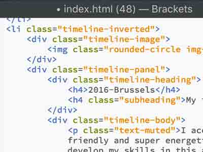


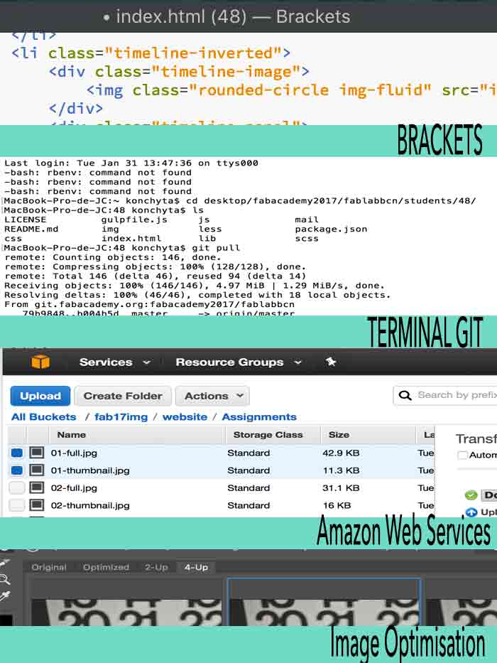


 Gif test>


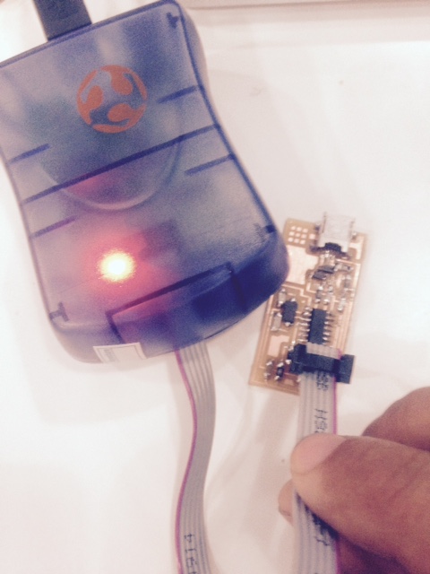


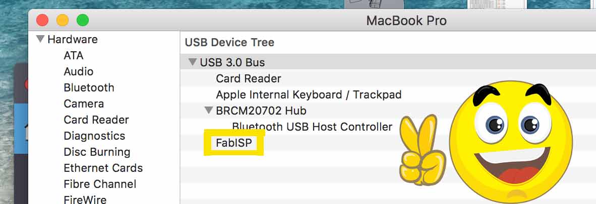


 .
.


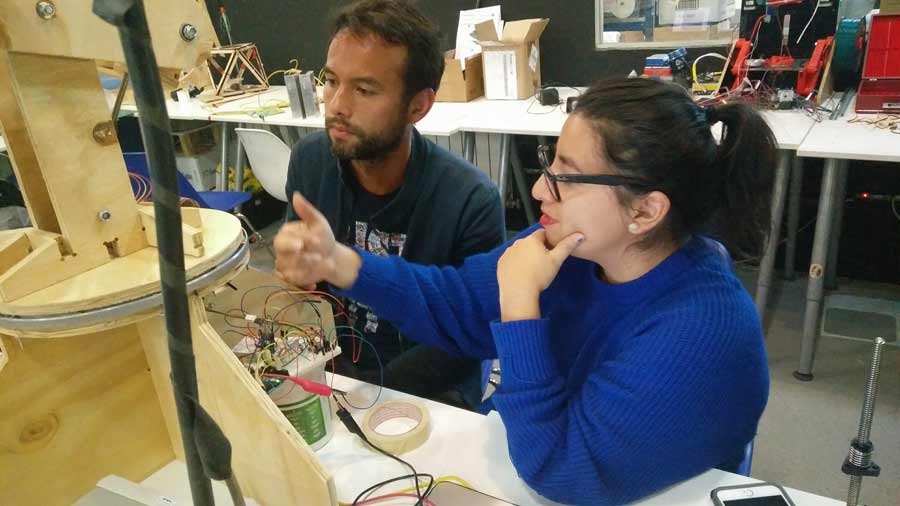
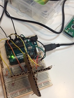
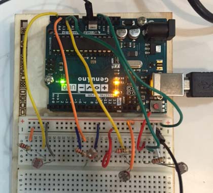
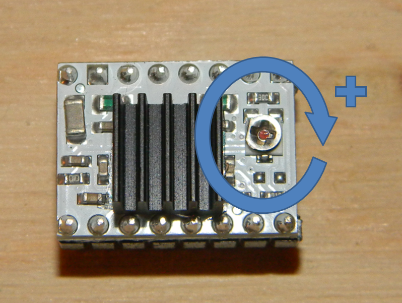


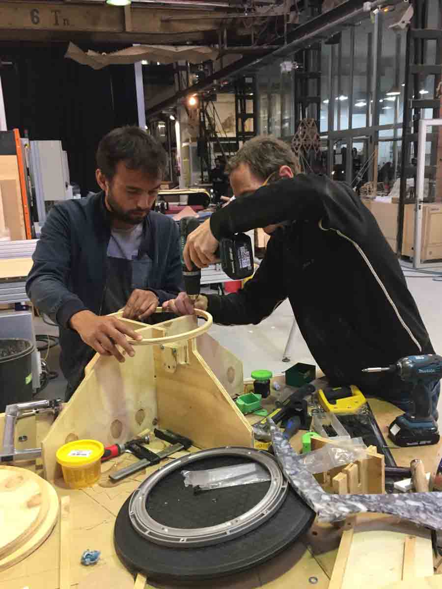
 .
.
 .
.
 .
.
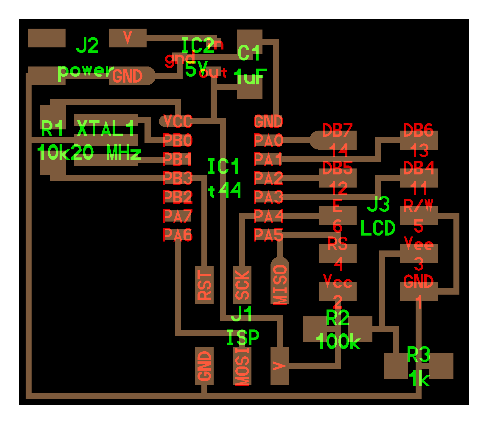


 .
. 


 .
.


 .
.


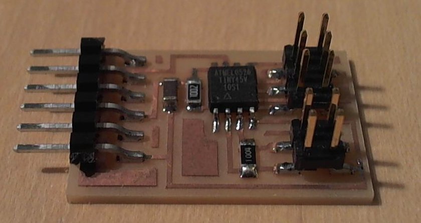
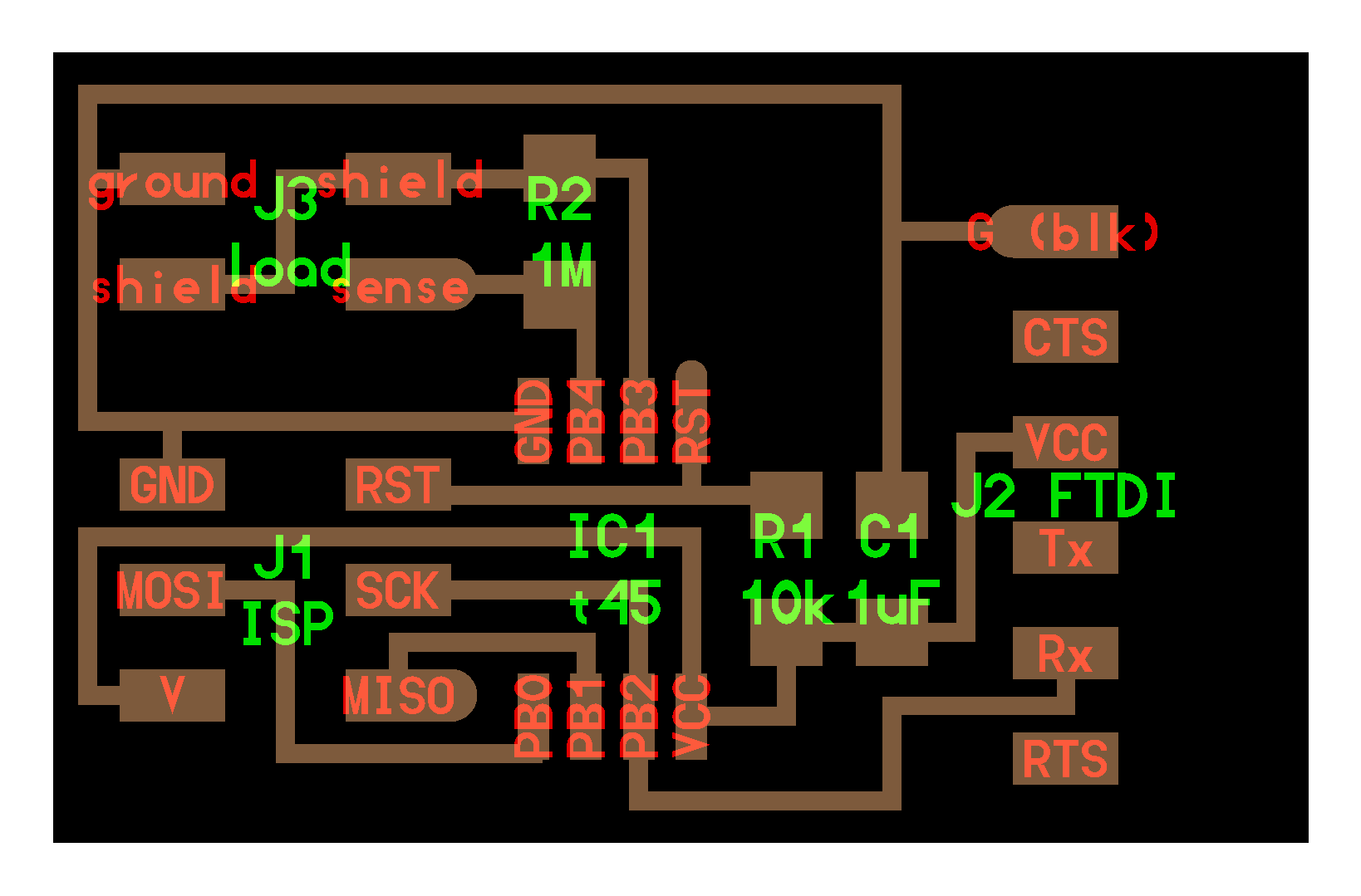