Described your design and fabrication process using words/images/screenshots..
Explained the programming process/es you used and how the microcontroller datasheet helped you.
Outlined problems and how you fixed them.
Included original design files and code.
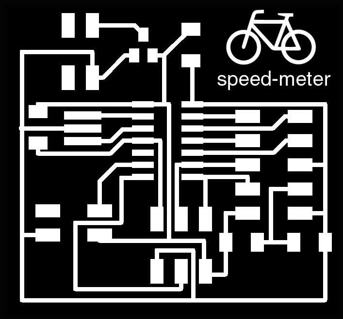
I wanted to make a speedometer for the bike, as it is something I will need to understand and implement for cadence measure for my final project. For that I will use a hall sensor. This will be addressed on the input device week, but I am still leaving the space and the connection ready for it. I have checked Rotem Abeles documentation, as the board he made was exactly the idea I had: everything fot the LED, a connection for a battery and a connection for an input board. I thought about having the input in the board too, but I decided my scheme would be more like this:
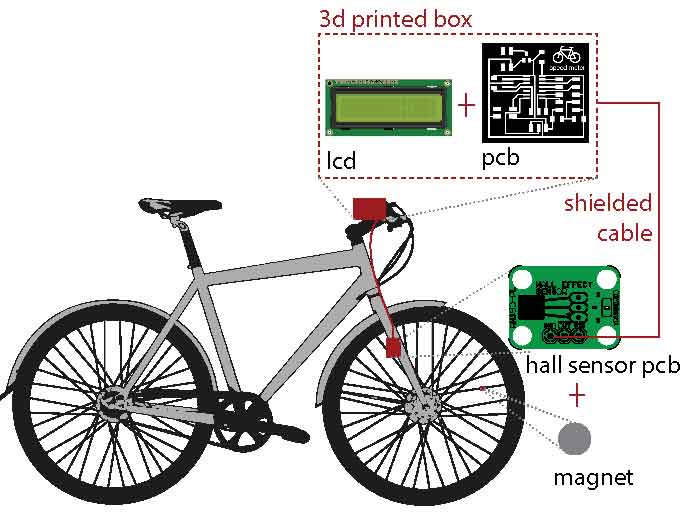
Having the board right next to the pcb and using a shielded cable would help with the noise. Or at least that is what I think, I will check it out in a couple weeks.
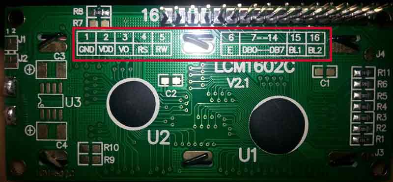
First thing I look carefully to Neil's lcd pcb. Afterwards I check the lcd datasheet to check the pin order and the voltage regulator I need. I used a LCM1602C, it is the basic one that comes with the Arduino kit, so the info on how to connect it is huge. Also the back of the board has a brief description of the pins.
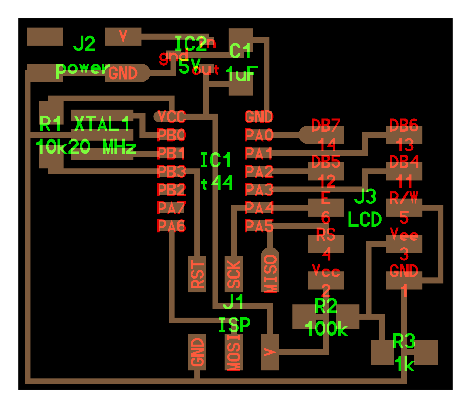
-Pin 1: GND, is connected directly to ground.
-Pin 2: VCC, is connected directly to VCC
-Pin 3: V0, the constrast of the lcd. Can be connected to a potentiometer to control it, or as Neil does to a resistor to have a fixed contrast.
-Pin 4:RS or "register select", this controls the memory of the LCD. Tells which memory register will be read.
-Pin 5: RW or "read/write", is connected directly to ground. This pin set the LCD to be write only (0) or to read from it (1). Most of the times we just use it to display messages, which is write, so we can connect it to ground directly.
-Pin 6: EN or "enable", this one enables registers
-Pins 7-14: DB0-DB7, data pins.
-Pin 15: BL1, this (with pin 16) is the backlight pin.
-Pin 16: BL2, this (with pin 15) is the backlight pin..
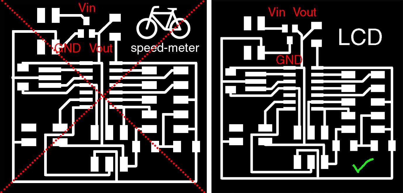
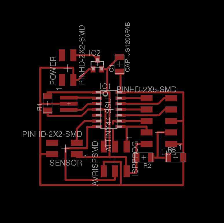
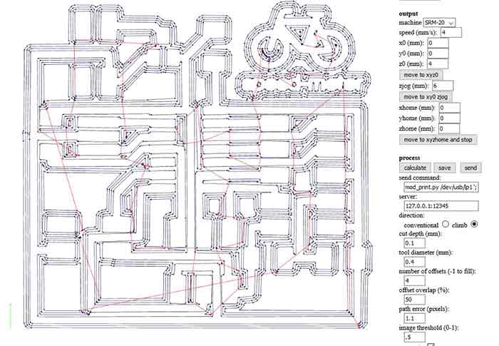
Something important to take in consideration is that the pin description and the actual layout of the pins are order reversed, so it is a common mistake to connect them the other way around. Once I had a fair understanding of how the pins worked I moved to Eagle and started with the schematics. And the pcb layout. After a while I had an OK board. I exported it as a PNG and did the photoshop adjustments in order to have the right size and outline. I was ready to use fabmodules for the genererating the G-code.
I didn't had time to mill and program the board this week, but I found a tutoria and an arduino sketch for calculating speed and distance on this webpage. The code is made for an Arduino board but it still is very similar to the oe I will use on my board. Compiling in on Arduino IDLE allowed me to realize I can't use a ATiny 44, the sketch uses 5628 bytes, while ATiny 44 only has 4k memory. I will have to change my board for a ATtiny 84. (The ATtiny 85 has not enough pins)

I finally got the time to mill the board during the molding and casting week. This forced me to use the Roland Modela instead of the XR-20, as these were being used to mill wax. It was my first time using this machine. The computer to run the Modela runs Ubuntu. I installed a virtual machine in my computer some weeks ago to get some experience with Linux and using this machine didn't feel that weid. This machine uses the old fab modules, the one that is installed on the machine. To start the program you need to call fab on linux terminal. Once the program is running is very similar to the online verison. Setting the type of file, and the process. Afterwards you only need to load the png, and choose the tool and make sure the settings are right. Fabmodules comunicates directly to the machine, whereas Rolan SRM-20 reads a G-code and launch it trhough its own software. The main diference with this machine it the Z setting. To do this you basically do it by hand: You have to lower the z enought to manually loose the tool, lowered by hand and tighten the tool back angain. The z height that is set wen you send the code is asumed as the z0 by the machine.
The other main diference is that there is not a PAUSE button. This Fab Modules is a Python program, and to stop it you need to kill the Python process by terminal. First you nedd to know which processes are runing, to do this type on terminal ps -A, then a list of all the processes runing will appear. If you are only interested on Python processes as we are now, you can type ps -A | grep python . A list of the processes will appear, usually by stoppping the last one the machine will stop. kill -0 3189.
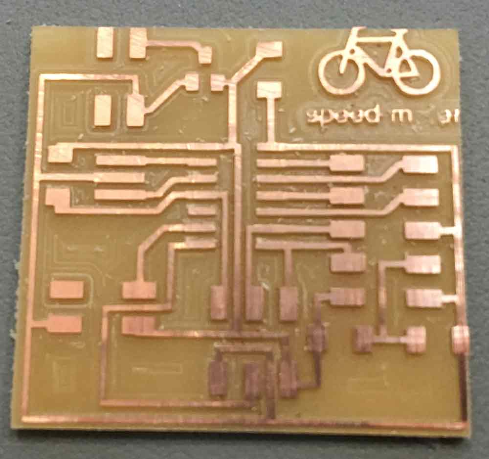
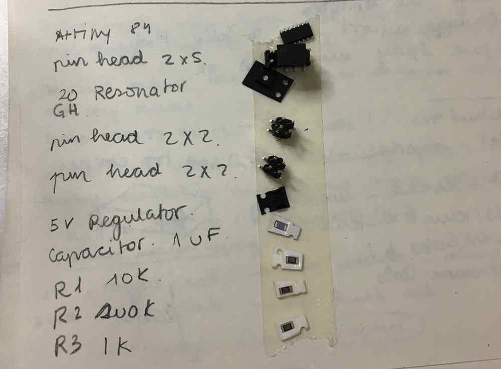
Our machine bed was not very flat and it took me various tries to get all the traces well cut. But I finally got it. After I checked all the components I needed and solder the board.
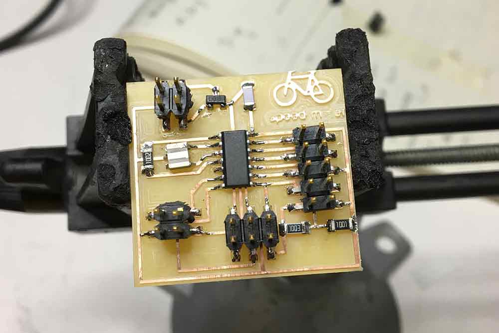
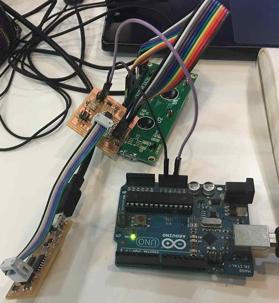
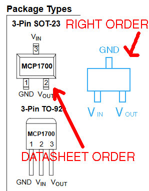
To program the board, I used my FabIsp. To be honest this week was not really about programming for me, as the code I was working on was to be used with both output and input boards. I used the "Hello World" example from LiquidCrystal library to check if everything was working correctly. I also wanted to use Neil's Hello World program just to check how compiling #C worked. I only tweeked Neil's code a little bit to display my name instead of "Hello World". To power the board I left 2 pins to connect to a battery, but for the time being I decided to use the arduino for power. When I connected the board to the power AHHHH!!! a line of smoke came out of my ATtiny 84... :( Checking more thoroughly I realised the problem was on the voltage regulator, it was wrongly connected. I read the wrong data sheet for my voltage regulator, the pin connections resulted on the wrong order, creating a short-circuit that burned the chip.
//
// hello.LCD.44.c
//
// LCD hello-world
//
// set lfuse to 0x5E for 20 MHz xtal
//
// Neil Gershenfeld code modified by Julia Leirado
// 11/14/10
//
// (c) Massachusetts Institute of Technology 2010
// This work may be reproduced, modified, distributed,
// performed, and displayed for any purpose. Copyright is
// retained and must be preserved. The work is provided
// as is; no warranty is provided, and users accept all
// liability.
//

#include
#include
#include

#define output(directions,pin) (directions |= pin) // set port direction for output
#define set(port,pin) (port |= pin) // set port pin
#define clear(port,pin) (port &= (~pin)) // clear port pin
#define pin_test(pins,pin) (pins & pin) // test for port pin
#define bit_test(byte,bit) (byte & (1 << bit)) // test for bit set

#define LCD_port PORTA
#define LCD_direction DDRA
#define DB7 (1 << PA0)
#define DB6 (1 << PA1)
#define DB5 (1 << PA2)
#define DB4 (1 << PA3)
#define E (1 << PA4)
#define RS (1 << PA5)

#define long_delay() _delay_ms(1000) // delay before redraw
#define lcd_delay() _delay_ms(10) // delay between commands
#define strobe_delay() _delay_us(1) // delay for strobe

//
// lcd_putchar
//    put character in lcdbyte
//
void lcd_putchar(char lcdbyte) {
   //
   // set RS for data
   //
   set(LCD_port, RS);
   //
   // output high nibble
   //
   if bit_test(lcdbyte, 7)
      set(LCD_port, DB7);
   else
      clear(LCD_port, DB7);
   if bit_test(lcdbyte, 6)
      set(LCD_port, DB6);
   else
      clear(LCD_port, DB6);
   if bit_test(lcdbyte, 5)
      set(LCD_port, DB5);
   else
      clear(LCD_port, DB5);
   if bit_test(lcdbyte, 4)
      set(LCD_port, DB4);
   else
      clear(LCD_port, DB4);
   //
   // strobe E
   //
   strobe_delay();
   set(LCD_port, E);
   strobe_delay();
   clear(LCD_port, E);
   //
   // wait
   //
   lcd_delay();
   //
   // output low nibble
   //
   if bit_test(lcdbyte, 3)
      set(LCD_port, DB7);
   else
      clear(LCD_port, DB7);
   if bit_test(lcdbyte, 2)
      set(LCD_port, DB6);
   else
      clear(LCD_port, DB6);
   if bit_test(lcdbyte, 1)
      set(LCD_port, DB5);
   else
      clear(LCD_port, DB5);
   if bit_test(lcdbyte, 0)
      set(LCD_port, DB4);
   else
      clear(LCD_port, DB4);
   //
   // strobe E
   //
   strobe_delay();
   set(LCD_port, E);
   strobe_delay();
   clear(LCD_port, E);
   //
   // wait and return
   //
   lcd_delay();
   }
//
// lcd_putcmd
//    put command in lcdbyte
//
void lcd_putcmd(char lcdbyte) {
   //
   // clear RS for command
   //
   clear(LCD_port, RS);
   //
   // output command bits
   //
   PORTA = lcdbyte;
   //
   // strobe E
   //
   strobe_delay();
   set(LCD_port, E);
   strobe_delay();
   clear(LCD_port, E);
   //
   // wait and return
   //
   lcd_delay();
   }
//
// lcd_putstring
//    put a null-terminated string in flash
//
void lcd_putstring(PGM_P message) {
   static uint8_t index;
   static char chr;
   index = 0;
   while (1) {
      chr = pgm_read_byte(&(message[index]));
      if (chr == 0)
         return;
      lcd_putchar(chr);
      ++index;
      }
   }
//
// lcd_init
//    initialize the LCD
//
void lcd_init() {
   //
   // power-up delay
   //
   lcd_delay();
   //
   // initialization sequence
   //
   lcd_putcmd(DB5+DB4);
   lcd_putcmd(DB5+DB4);
   lcd_putcmd(DB5+DB4);
   //
   // 4-bit interface
   //
   lcd_putcmd(DB5);
   //
   // two lines, 5x7 font
   //
   lcd_putcmd(DB5);
   lcd_putcmd(DB7);
   //
   // display on
   //
   lcd_putcmd(0);
   lcd_putcmd(DB7+DB6+DB5);
   //
   // entry mode
   //
   lcd_putcmd(0);
   lcd_putcmd(DB6+DB5);
   }

int main(void) {
   //
   // main
   //
   // set clock divider to /1
   //
   CLKPR = (1 << CLKPCE);
   CLKPR = (0 << CLKPS3) | (0 << CLKPS2) | (0 << CLKPS1) | (0 << CLKPS0);
   //
   // initialize LCD pins
   //
   clear(LCD_port, DB7);
   output(LCD_direction, DB7);
   clear(LCD_port, DB6);
   output(LCD_direction, DB6);
   clear(LCD_port, DB5);
   output(LCD_direction, DB5);
   clear(LCD_port, DB4);
   output(LCD_direction, DB4);
   clear(LCD_port, E);
   output(LCD_direction, E);
   clear(LCD_port, RS);
   output(LCD_direction, RS);
   //
   // initialize LCD
   //
   lcd_init();
   //
   // main loop
   //
   while (1) {
      //
      // go to zero position
      //
      lcd_putcmd(0);
      lcd_putcmd(DB5);
      //
      // print first line from flash
      //
      static const char line1[] PROGMEM = "Julia";
      lcd_putstring((PGM_P) line1);
      //
      // move to second line
      //
      lcd_putcmd(DB7+DB6);
      lcd_putcmd(0);
      //
      // print second line from flash
      //
      static const char line2[] PROGMEM = "Leirado";
      lcd_putstring((PGM_P) line2);
      //
      // pause
      //
      long_delay();
      //
      // clear display
      //
      lcd_putcmd(0);
      lcd_putcmd(DB4);
      }
}
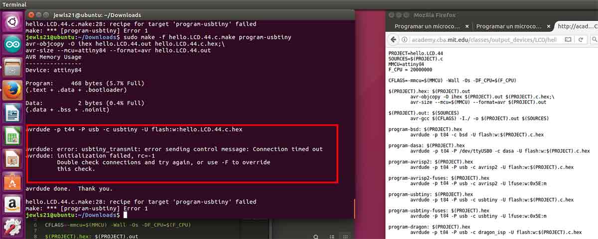
After fixing the electronics, I tried to compile and program the board using Ubuntu. It is something I want to keep up with, as I want to get more comfortable with this SO. I modified the .Make program for a ATtiny 84, but still wasn't able to do it. When I did sudo make I keep geting this error with the usbtiny drivers. Apparently there are some rules files I have to modify first to get it working, but as I wasn't able to fix it, I moved back to Windows.
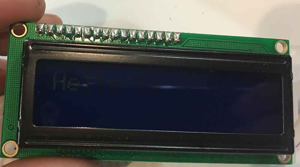
I had installed AVRDude some weeks ago, this is a c compiler. I used the Git Bash to compile the code. I use Git Bash instead of Windows Terminal, because I like it more and I am getting used to Linux terminal. Once I had loaded the program the LCD was working but not well. The text was not legible at all.
//
// hello.LCD.44.c
//
// LCD hello-world
//
// set lfuse to 0x5E for 20 MHz xtal
//
// Neil Gershenfeld code modified by Julia Leirado
// 11/14/10
//
// (c) Massachusetts Institute of Technology 2010
// This work may be reproduced, modified, distributed,
// performed, and displayed for any purpose. Copyright is
// retained and must be preserved. The work is provided
// as is; no warranty is provided, and users accept all
// liability.
//

#include
#include
#include

#define output(directions,pin) (directions |= pin) // set port direction for output
#define set(port,pin) (port |= pin) // set port pin
#define clear(port,pin) (port &= (~pin)) // clear port pin
#define pin_test(pins,pin) (pins & pin) // test for port pin
#define bit_test(byte,bit) (byte & (1 << bit)) // test for bit set

#define LCD_port PORTA
#define LCD_direction DDRA
#define DB7 (1 << PA0)
#define DB6 (1 << PA1)
#define DB5 (1 << PA2)
#define DB4 (1 << PA3)
#define E (1 << PA4)
#define RS (1 << PA5)

#define long_delay() _delay_ms(1000) // delay before redraw
#define lcd_delay() _delay_ms(10) // delay between commands
#define strobe_delay() _delay_us(1) // delay for strobe

//
// lcd_putchar
//    put character in lcdbyte
//
void lcd_putchar(char lcdbyte) {
   //
   // set RS for data
   //
   set(LCD_port, RS);
   //
   // output high nibble
   //
   if bit_test(lcdbyte, 7)
      set(LCD_port, DB7);
   else
      clear(LCD_port, DB7);
   if bit_test(lcdbyte, 6)
      set(LCD_port, DB6);
   else
      clear(LCD_port, DB6);
   if bit_test(lcdbyte, 5)
      set(LCD_port, DB5);
   else
      clear(LCD_port, DB5);
   if bit_test(lcdbyte, 4)
      set(LCD_port, DB4);
   else
      clear(LCD_port, DB4);
   //
   // strobe E
   //
   strobe_delay();
   set(LCD_port, E);
   strobe_delay();
   clear(LCD_port, E);
   //
   // wait
   //
   lcd_delay();
   //
   // output low nibble
   //
   if bit_test(lcdbyte, 3)
      set(LCD_port, DB7);
   else
      clear(LCD_port, DB7);
   if bit_test(lcdbyte, 2)
      set(LCD_port, DB6);
   else
      clear(LCD_port, DB6);
   if bit_test(lcdbyte, 1)
      set(LCD_port, DB5);
   else
      clear(LCD_port, DB5);
   if bit_test(lcdbyte, 0)
      set(LCD_port, DB4);
   else
      clear(LCD_port, DB4);
   //
   // strobe E
   //
   strobe_delay();
   set(LCD_port, E);
   strobe_delay();
   clear(LCD_port, E);
   //
   // wait and return
   //
   lcd_delay();
   }
//
// lcd_putcmd
//    put command in lcdbyte
//
void lcd_putcmd(char lcdbyte) {
   //
   // clear RS for command
   //
   clear(LCD_port, RS);
   //
   // output command bits
   //
   PORTA = lcdbyte;
   //
   // strobe E
   //
   strobe_delay();
   set(LCD_port, E);
   strobe_delay();
   clear(LCD_port, E);
   //
   // wait and return
   //
   lcd_delay();
   }
//
// lcd_putstring
//    put a null-terminated string in flash
//
void lcd_putstring(PGM_P message) {
   static uint8_t index;
   static char chr;
   index = 0;
   while (1) {
      chr = pgm_read_byte(&(message[index]));
      if (chr == 0)
         return;
      lcd_putchar(chr);
      ++index;
      }
   }
//
// lcd_init
//    initialize the LCD
//
void lcd_init() {
   //
   // power-up delay
   //
   lcd_delay();
   //
   // initialization sequence
   //
   lcd_putcmd(DB5+DB4);
   lcd_putcmd(DB5+DB4);
   lcd_putcmd(DB5+DB4);
   //
   // 4-bit interface
   //
   lcd_putcmd(DB5);
   //
   // two lines, 5x7 font
   //
   lcd_putcmd(DB5);
   lcd_putcmd(DB7);
   //
   // display on
   //
   lcd_putcmd(0);
   lcd_putcmd(DB7+DB6+DB5);
   //
   // entry mode
   //
   lcd_putcmd(0);
   lcd_putcmd(DB6+DB5);
   }

int main(void) {
   //
   // main
   //
   // set clock divider to /1
   //
   CLKPR = (1 << CLKPCE);
   CLKPR = (0 << CLKPS3) | (0 << CLKPS2) | (0 << CLKPS1) | (0 << CLKPS0);
   //
   // initialize LCD pins
   //
   clear(LCD_port, DB7);
   output(LCD_direction, DB7);
   clear(LCD_port, DB6);
   output(LCD_direction, DB6);
   clear(LCD_port, DB5);
   output(LCD_direction, DB5);
   clear(LCD_port, DB4);
   output(LCD_direction, DB4);
   clear(LCD_port, E);
   output(LCD_direction, E);
   clear(LCD_port, RS);
   output(LCD_direction, RS);
   //
   // initialize LCD
   //
   lcd_init();
   //
   // main loop
   //
   while (1) {
      //
      // go to zero position
      //
      lcd_putcmd(0);
      lcd_putcmd(DB5);
      //
      // print first line from flash
      //
      static const char line1[] PROGMEM = "Julia";
      lcd_putstring((PGM_P) line1);
      //
      // move to second line
      //
      lcd_putcmd(DB7+DB6);
      lcd_putcmd(0);
      //
      // print second line from flash
      //
      static const char line2[] PROGMEM = "Leirado";
      lcd_putstring((PGM_P) line2);
      //
      // pause
      //
      long_delay();
      //
      // clear display
      //
      lcd_putcmd(0);
      lcd_putcmd(DB4);
      }
}
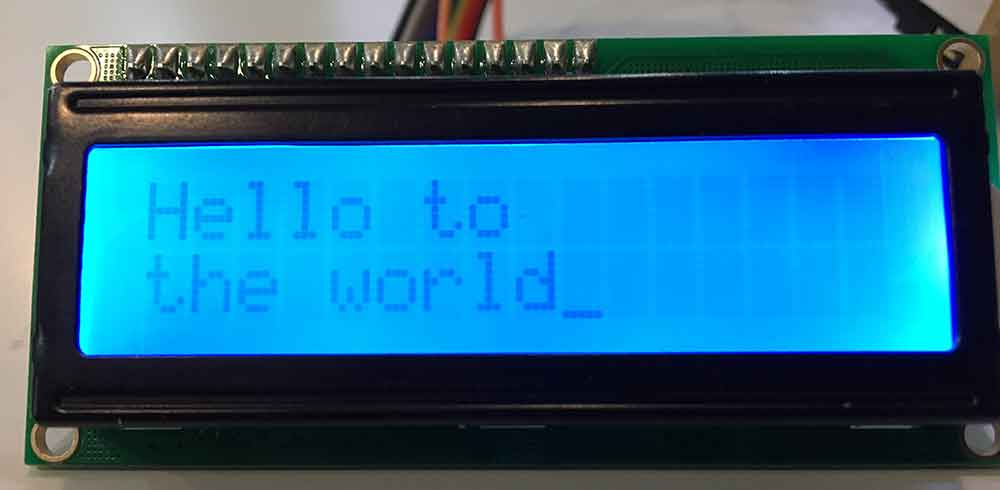
This was because this new model of the liquid crystal LCD, has a backgroun Led, and the las 2 pins, BL1 and BL2, should have been connected to 5V and GND respectively. As I hadn't though of it during the board design, I connected them to the ISP pins. Once the led was on, the LCD was more readible, even though V0, could benefit for a change on the resistance. That is the reason V0 pin is usually connected to a potentiometer instead of a resistance, to be able to change the contrast of the LCD once everything is connected.
BACK HOME <<<