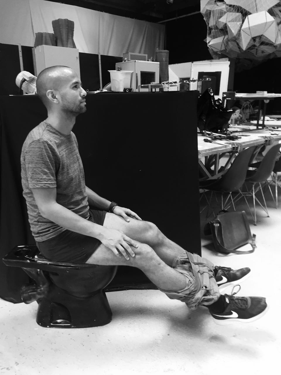
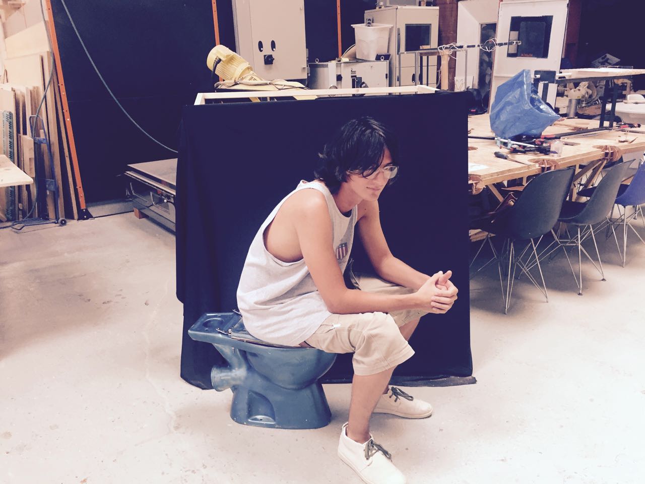
The toilet seat is one of the greatest incubator for ideas.
A REAL PROBLEM FOR MAN
When is the last time you weight yourself? Whether you cannot locate the scale in the bathroom, or forgot about using it, or just have no space for a scale, a mon only weight himself every two months.
INVESTIGATION
Where is the one place we go at least once a day?
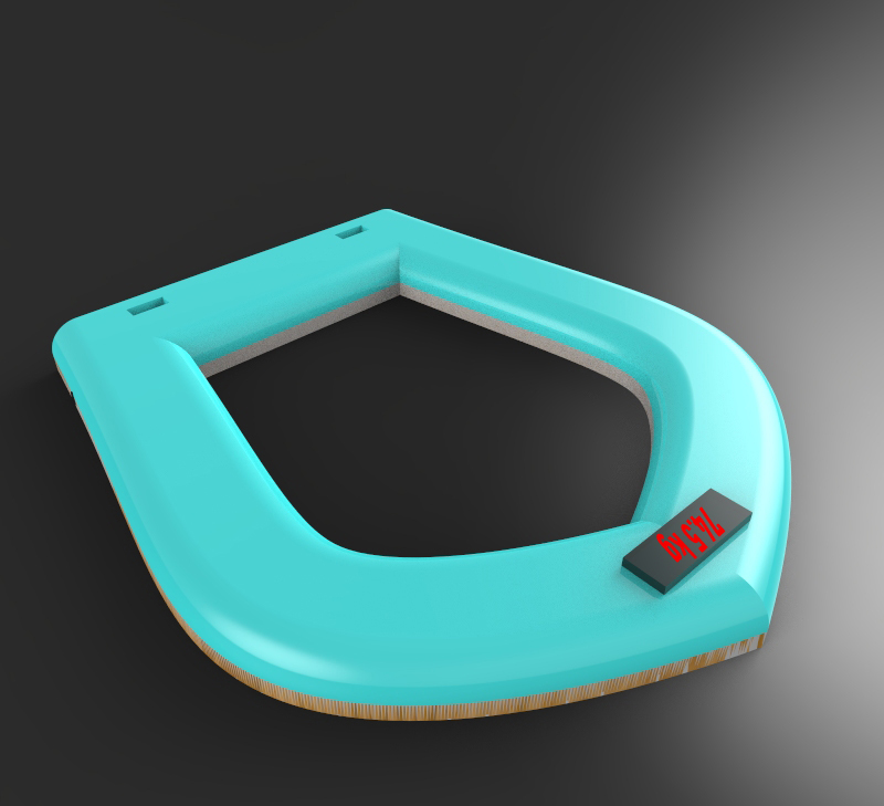
SOLUTION
An integrated toilet seat/ toilet mat seems the ideal solution, and idea that was suggested 7 years ago, but not yet commercialised
HOW WAS THE TOILET SEAT SCALE BUILT?
This is far from perfect but I am very happy I could make it happen
P1.CURRENT STATE & DESIGN OPTIONS
What exists today? and What are my design options?
P2.REVERSE_ENGINEERING
Attempt to dismantle a commercial bathroom scale to learn from it
P3.DATA_SENSING
Clearly the hardest part of the project
P4.BUIDLING THE FIRST PROTOTYPE
More text
P5. FINAL PROTOTYPE
Not as beautiful as I would have wanted but very happy it works
P6. GETTING READY FOR THE MAKER FAIRE
It was a really excting moment to see people trying the prototype
Surpringsly or not, there were very little done in this area. Except maybe this full toilet scale developped almost 10 years ago. Very interesting prototype to study but very heavy installation. The only other prototype I could find was only a graphic designer excercise, and not a prototype.
Overview of My Product Design Options
Each solution has advantages & benefits. Ideally i would like to favour simplicity of use & design. However this is an environement with water and electricty so SAFETY is actually paramount.
When studying design option, I Need to think about what can go wrong as this influence the design (Switches, kG/Ips conversion, Water risk, cleaning, kids, mens pissing, electricity, fixation selected, general safety)
P2.REVERSE_ENGINEERING
What can I learn from dismantling a commercial scale
Trying to recreate the board that you can find in a commercial weight scale
Reverse engineering a bathroom scale
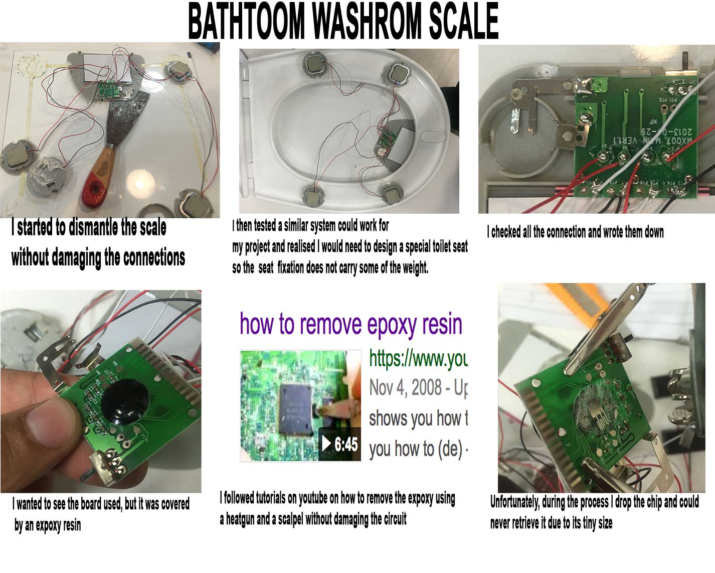
In March 2017 I went to buy an inexpensive commercial scale (20EUR) and started to take pieces out. I did this at the same time as INPUT WEEK assignement. I was relatively suprised by the apparent complexity of the electrical circuit. However when looking at it in more details I could see it was comprised of only a few electronic pieces put together
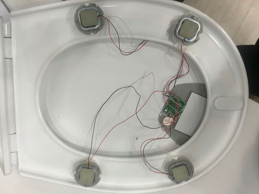
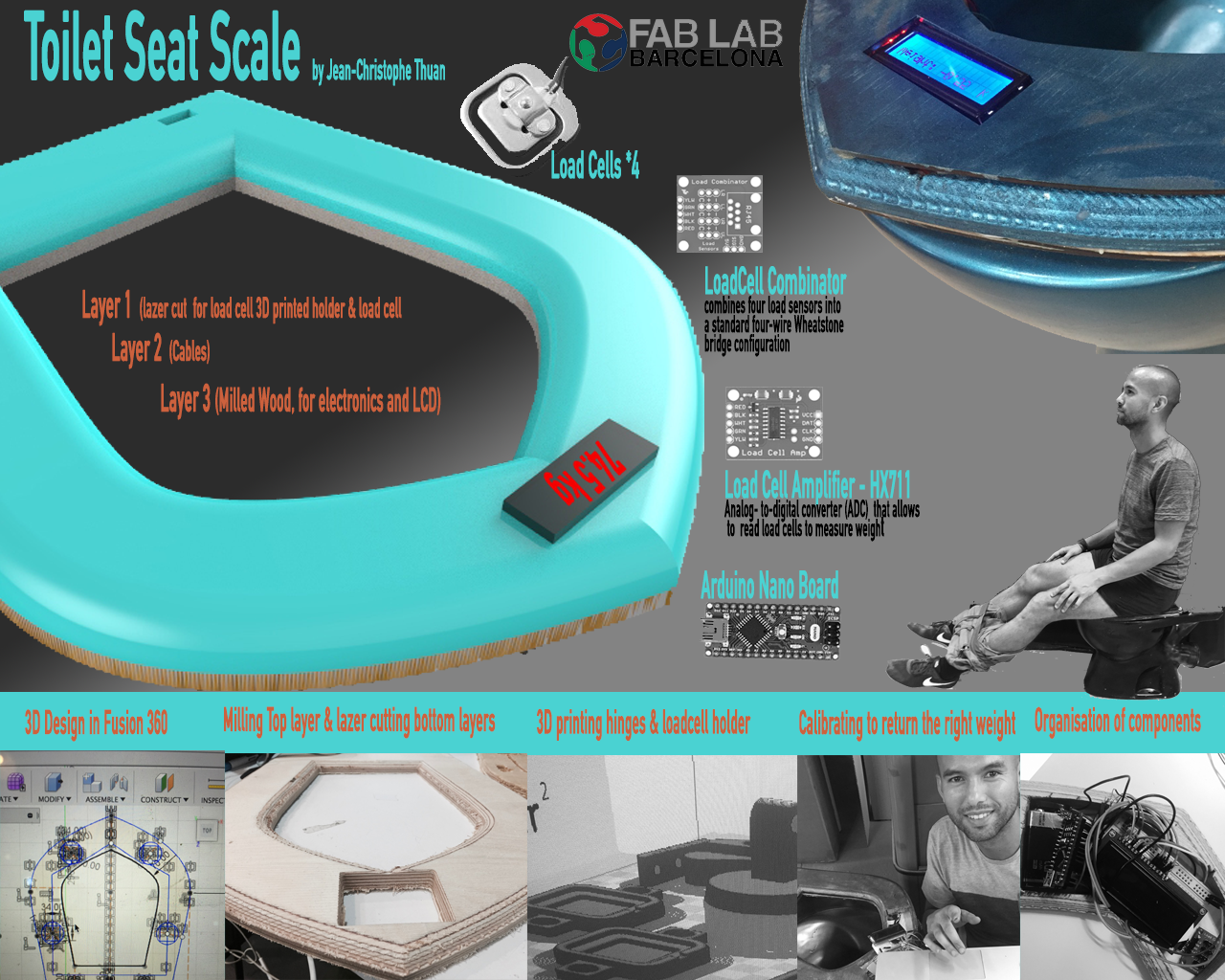
4 load sensors in each corner of the scale I find out it is actually much cheaper to source load sensors this way rather than buying them as separate electronic component (10 EUR a load sensor) - link here
A set of 4 plastic cover to connect to the 4 load sensors to the surface of the floor
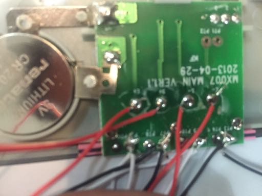
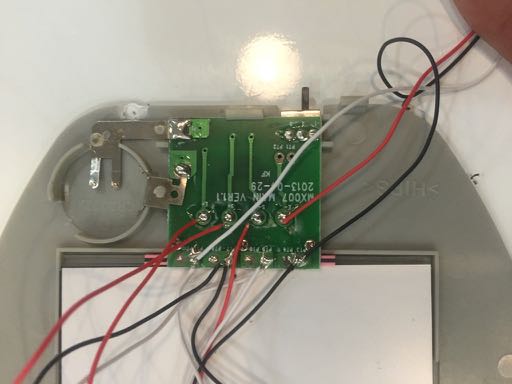
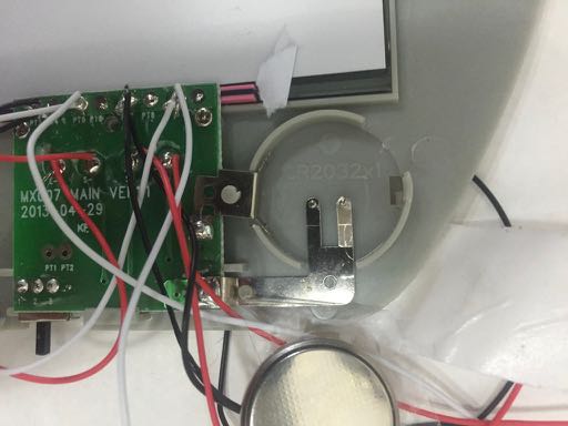
A small circuit to hold the coin cell battery and connect it the main board
A Load amplifier type H711 (more info on this later) between the load cells & the main board
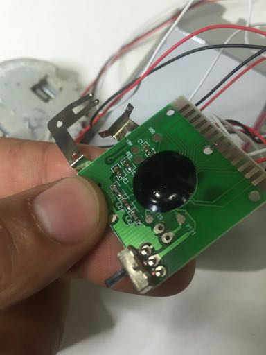
A LCD screen directly connected to the main board. No cables as this reduces costs & complexity I imagine
The main board that takes value from the load cell and display it on the LCD
The microcontroller of the main board is protected/hidden by a expoxy layer
A mechanical switch to connected to the microcontroller via electrical connection to change from KG to Pound
Software wise, the program must have a sleep mode, and a Capacity/Step sensor type to swtch on when someone stands on the scale.
The process was interesting but I accidently lost the chip (microcontroller) used after removing the epoxy resin protecting the chip using a heat gun,
Some more pictures of the process
P3.DATA_SENSING
Feedback
Clearly the most difficult part that made me almost give up on this project
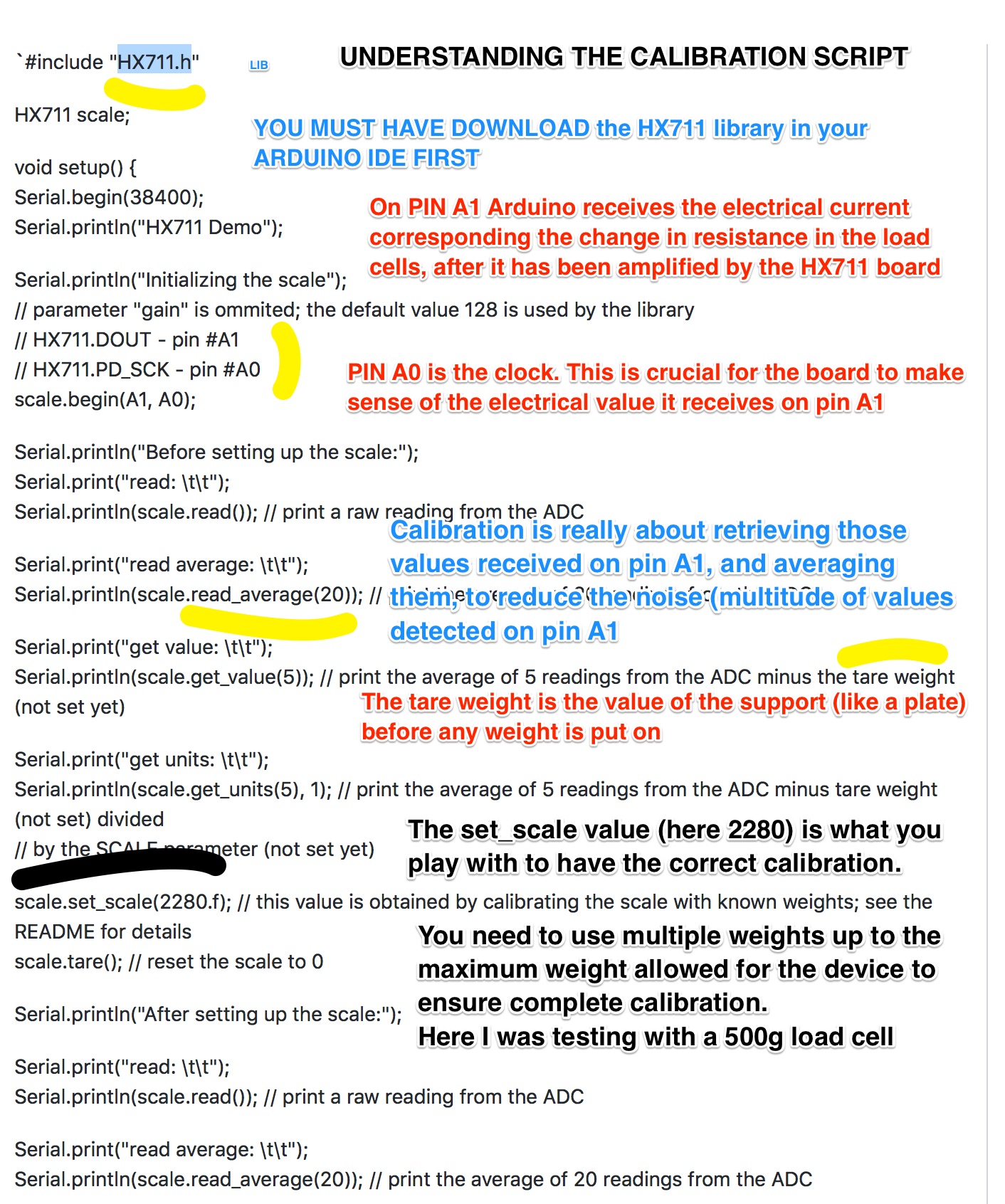
Click here to better understand how calibration works
Download the HX711 Library that will need for your program in Arduino
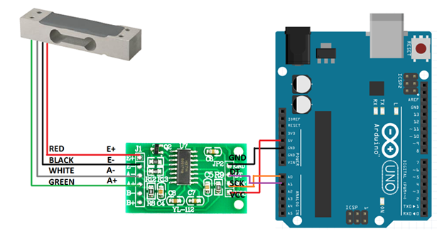
DATA SENSOR with one 4 wires load cell
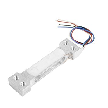
I initially started by sourcing from amazon a 500g load cell and an HX711 amplifier from amazon to test the mechanism. The reason I need an voltage amplifier is that the current data we get back from the load cell is so small it needs to be amplified to be read accurately in Arduino
The first hurdle was to get the load cell to work. During the first days I could not get any data values, so I started resoldering the cable of the load cell, but no sucess. So I decided to purchase another load cell (10kg value this time) and another amplifier. After a few days they arrive and could start working on it again.
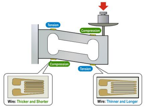
What is cell load amplifier?
It is best explained in Sparkfun (link here): A load Amplifier is a small breakout board for the HX711 IC that allows you to easily read load cells to measure weight. By connecting the amplifier to your microcontroller you will be able to read the changes in the resistance of the load cell, and with some calibration you’ll be able to get very accurate weight measurements
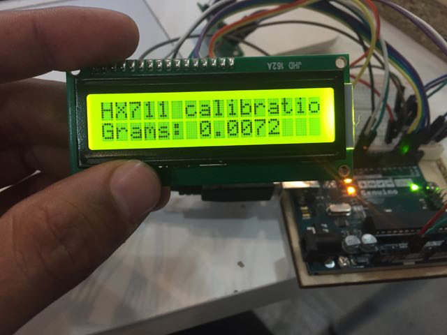
I followed a couple of instructables to do this, and not all were working. Actually only one arduino code would work for me. To achieve this I installed the HX711 library in Arduino and started running the calibration sequence with a 100g weight
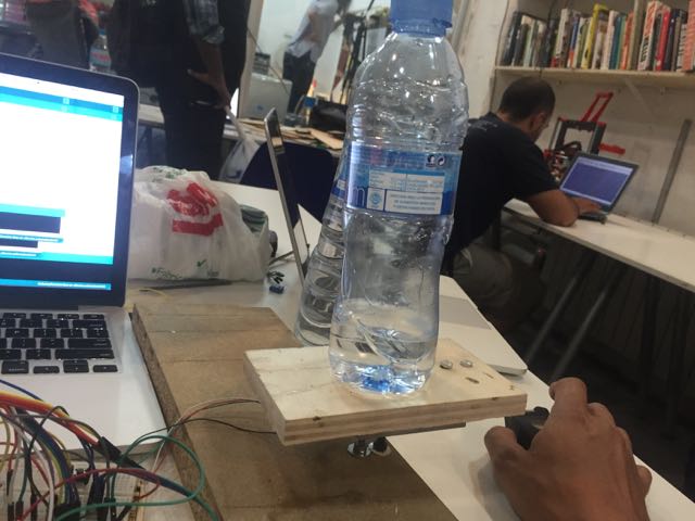
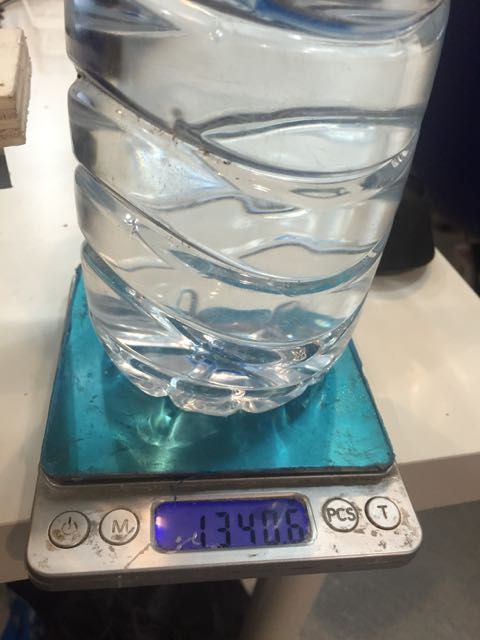
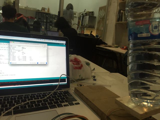
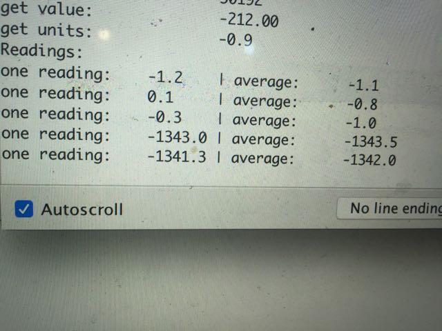
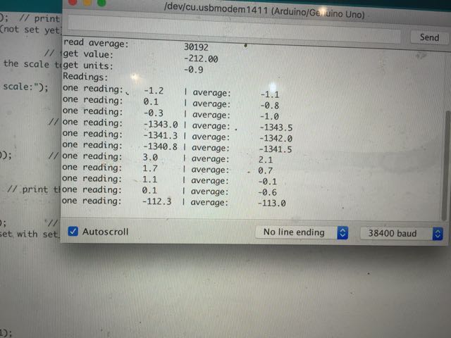
Based on the data input, I could modify the calibration in the script, to achieve the 100g weight reading. I then went on to do the same with a heavier weight (which is recommended), a bottle with water of 1340g
Testing a lower weight and changing from negative to positive value: for some reasons the calibration was working but my values were negative, so I first check the excitation of the load cell was correctly wired, and it was, so I modified the code to display positive values by multiplying by minus 1
How does calibration work
The best way to explained calibration is probably to go through the IDE skecth (link in the links section) & explain each step. There are actually multiple calibration code that can be used that work more or less well for the load cell you use
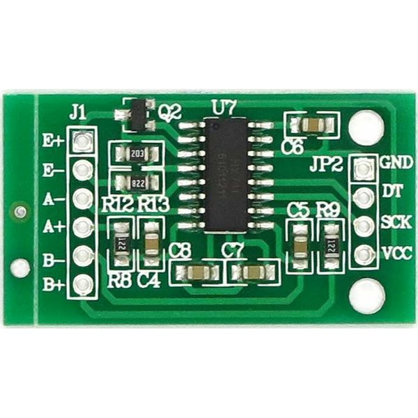
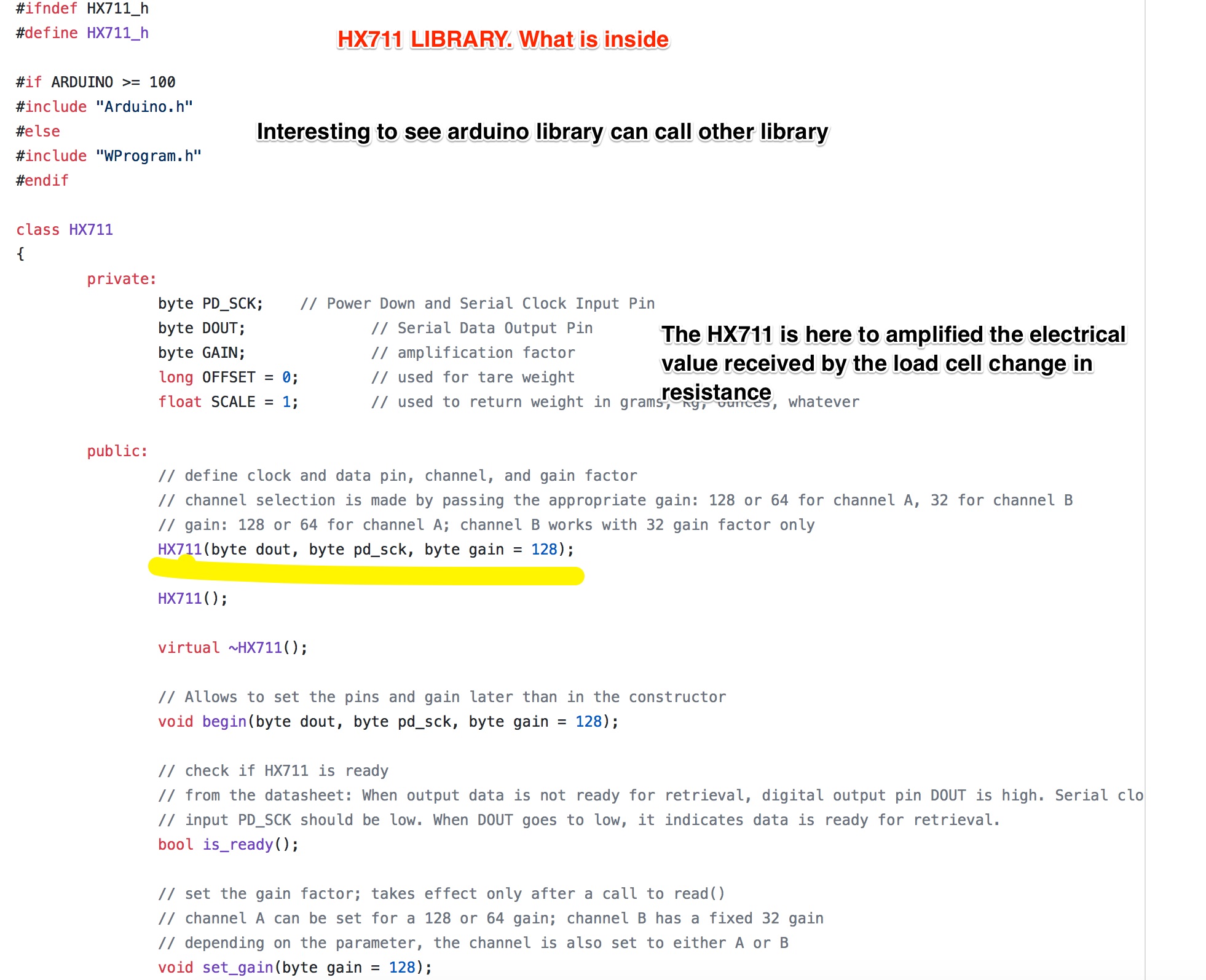
What is the HX711?
We often talk about HX711 as both an electrical circuit and an arduino library, both working hands in hands
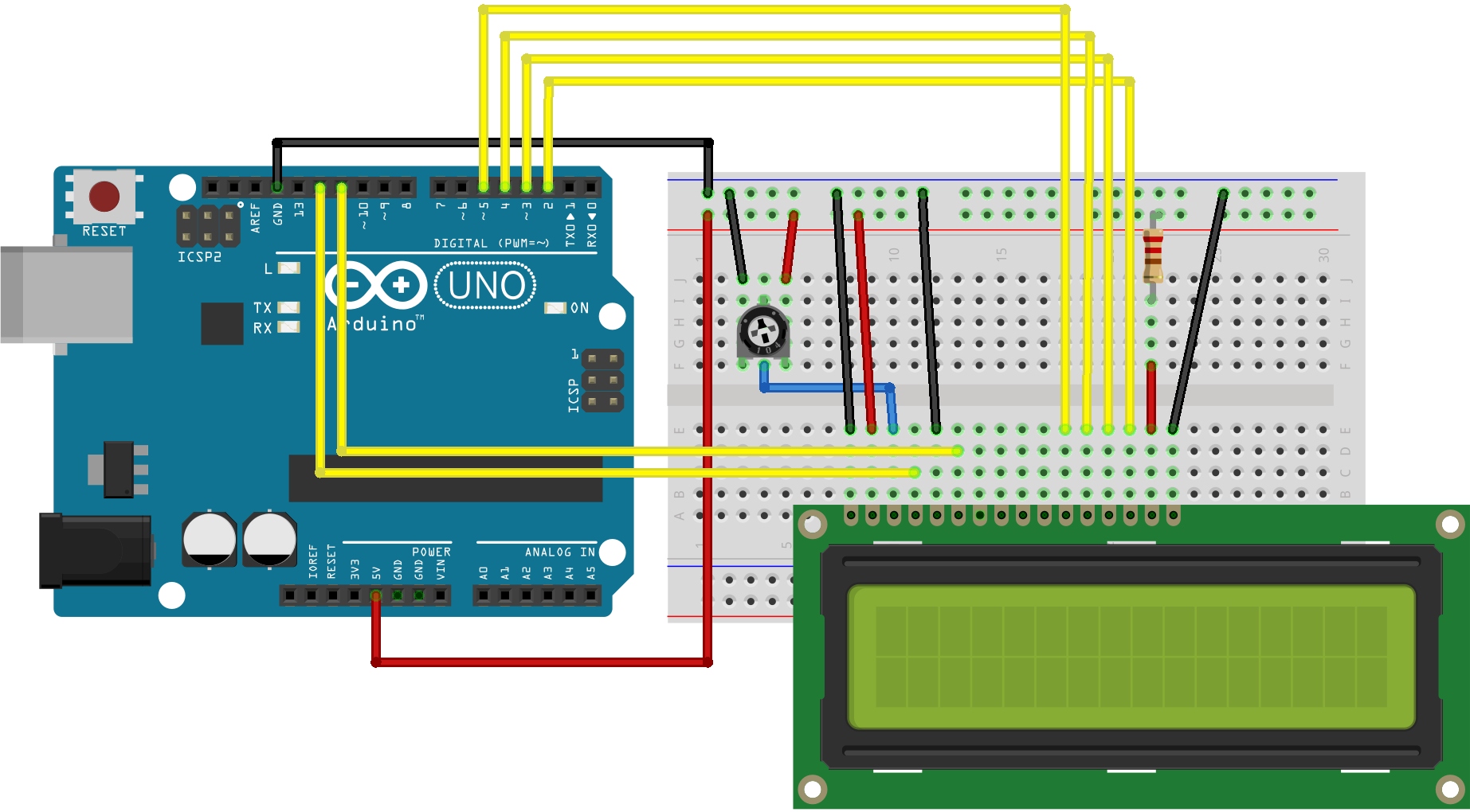
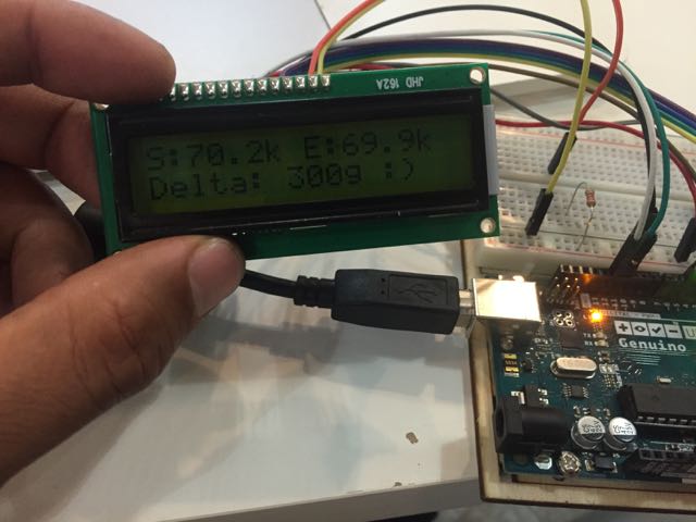
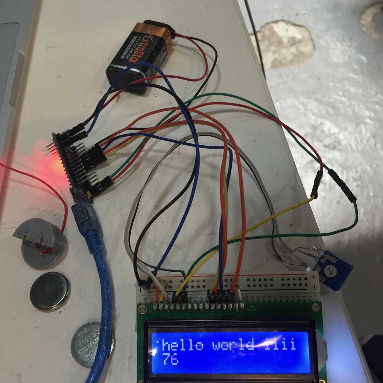
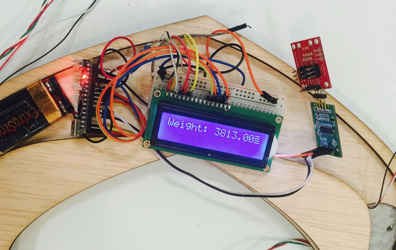
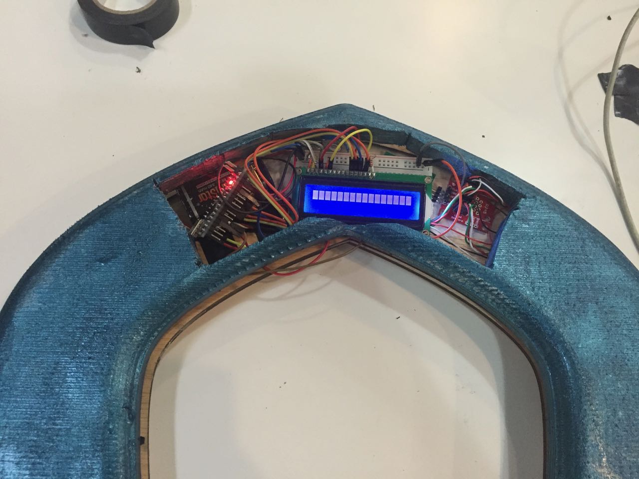
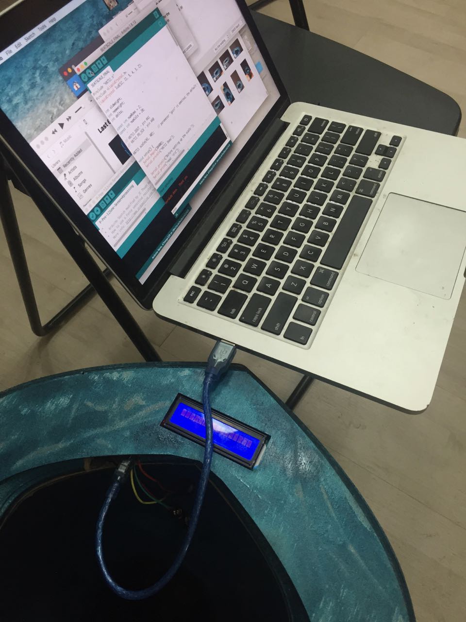
Adding a LCD screen to visualise the data
After following the instruction on how wire a LCD to an arduino, adding the LCD.Crystal library, i had to play with the potentiometer to get the right constrast display of the LCD. I also amended the code to display some text
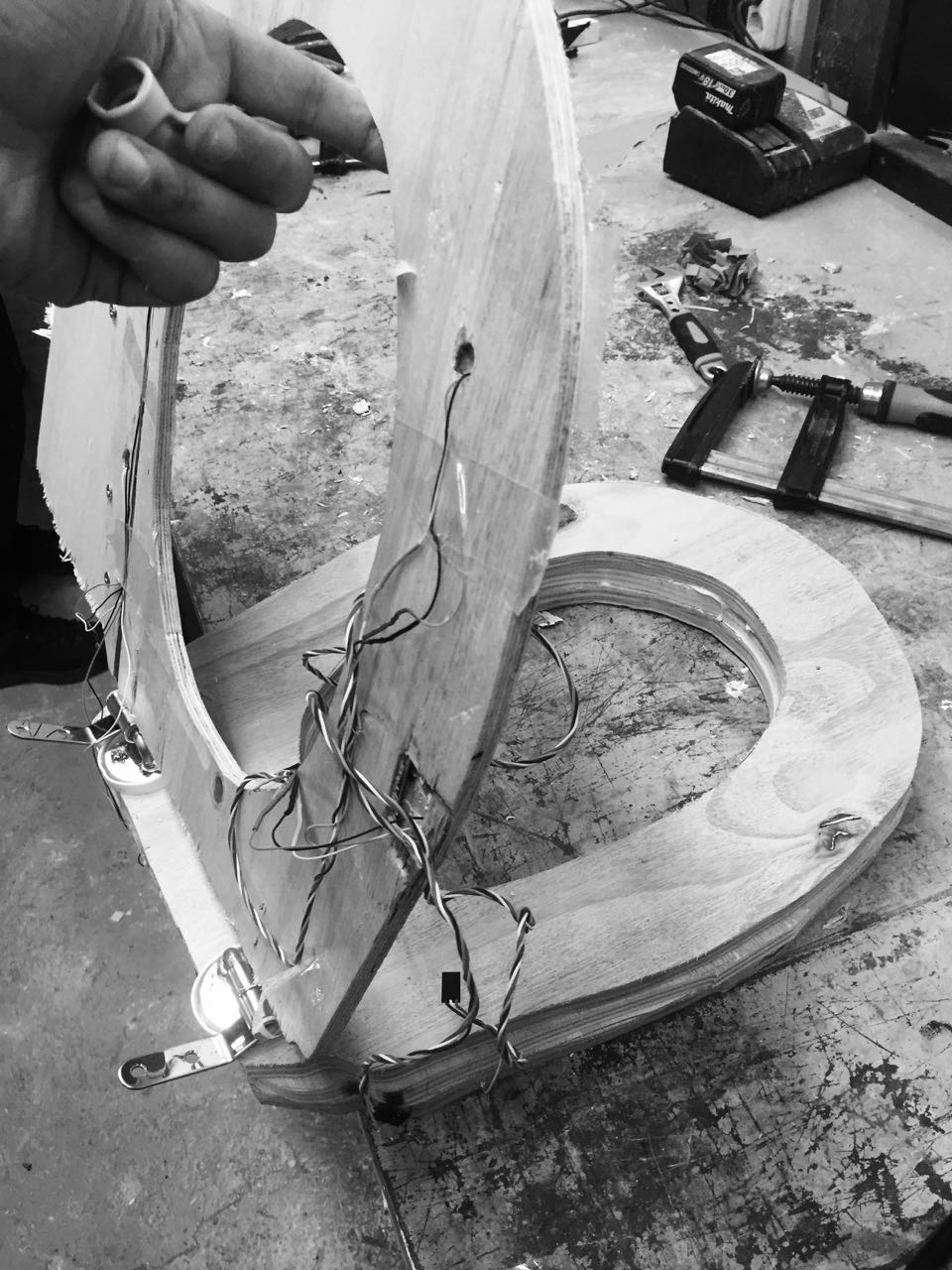
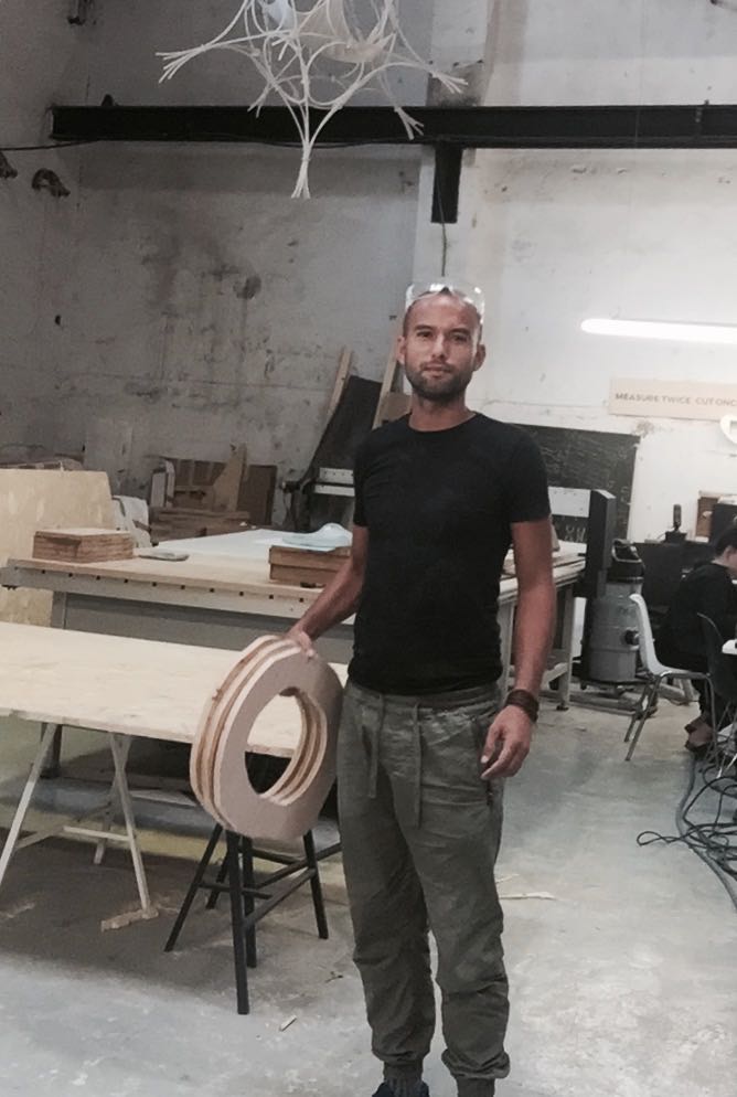
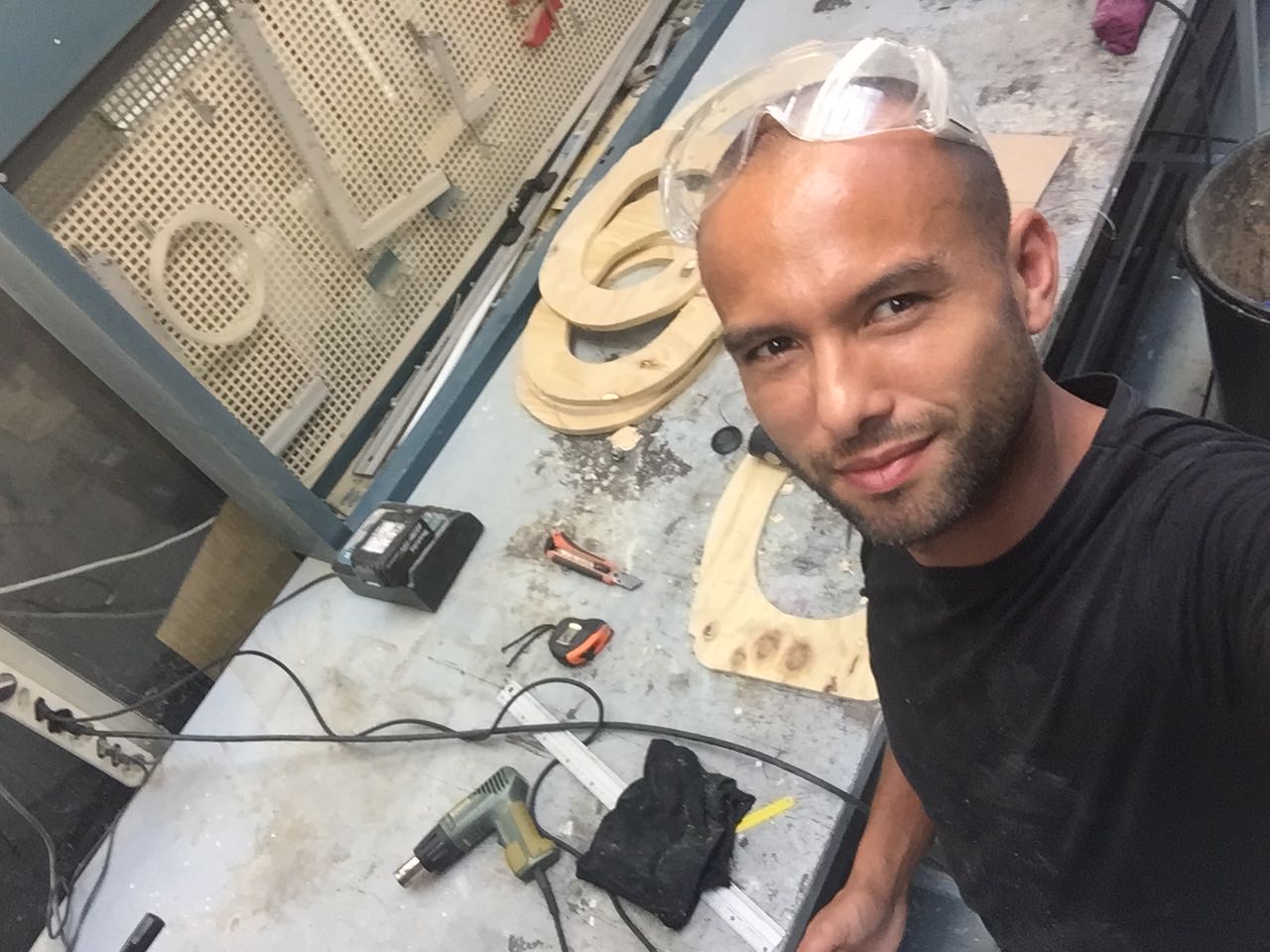
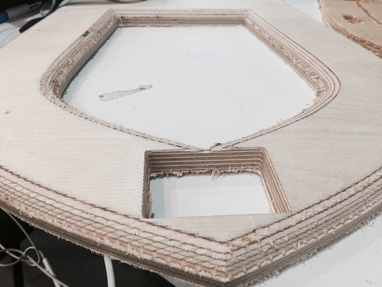
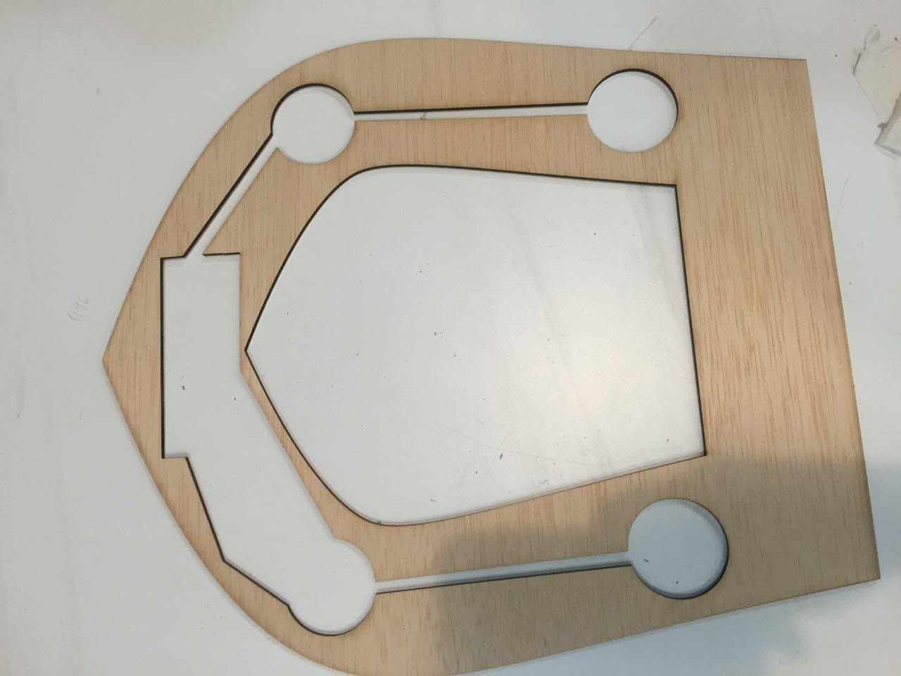
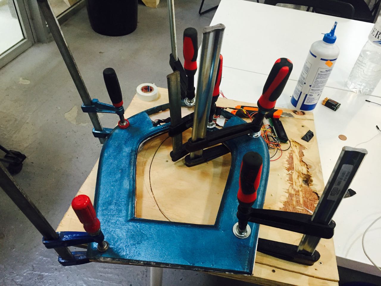
I cut with a electrical jig saw 4 layers of a 8mm plywood we had a the lab
Out of those 4 layers i created a mock up toilet seat
Making the electronics
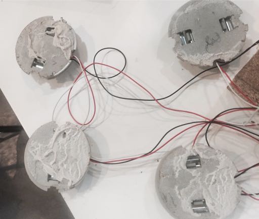
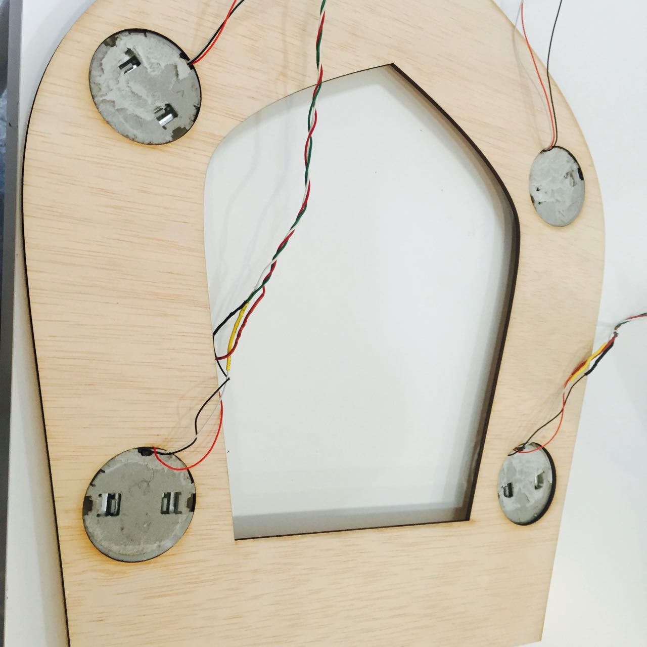
Using a 3 wires load cell from a commercial scale
It is 4 to 8 times cheaper to take 3 wires load cell from a commercial scale rather than buying them separately. However there is a drawback to this: no datasheet for the loadcell, and this can make life very complicated as I experienced when you face an issue. Debugging is more complicated as you are never sure about the load cell you use (max load, epoxy used for wires,etc...)
I had a number of issues later on in the process from the load cells I took out from the commercial scale, that i had to test each one (see example below)
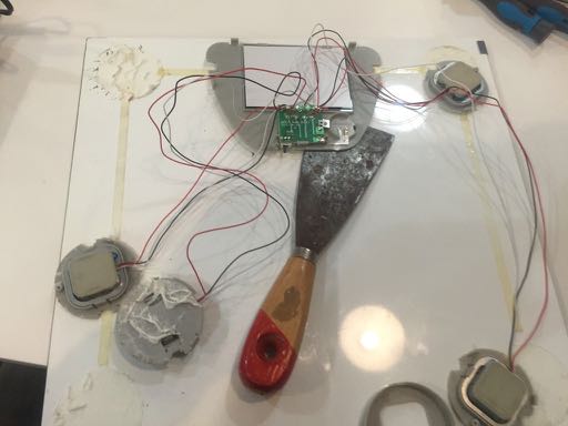
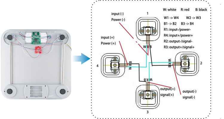
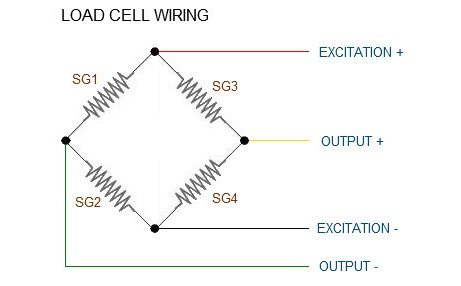
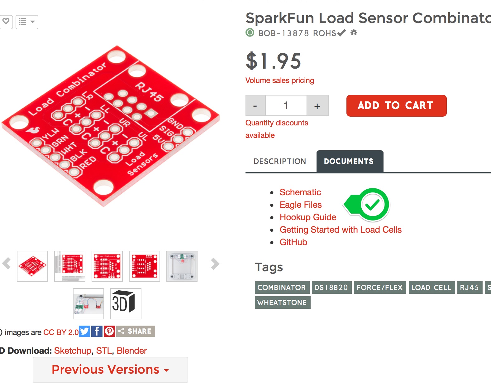
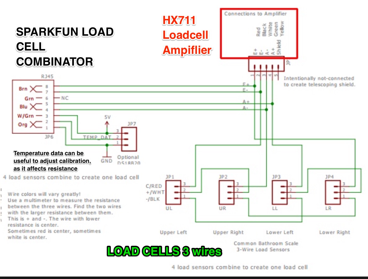
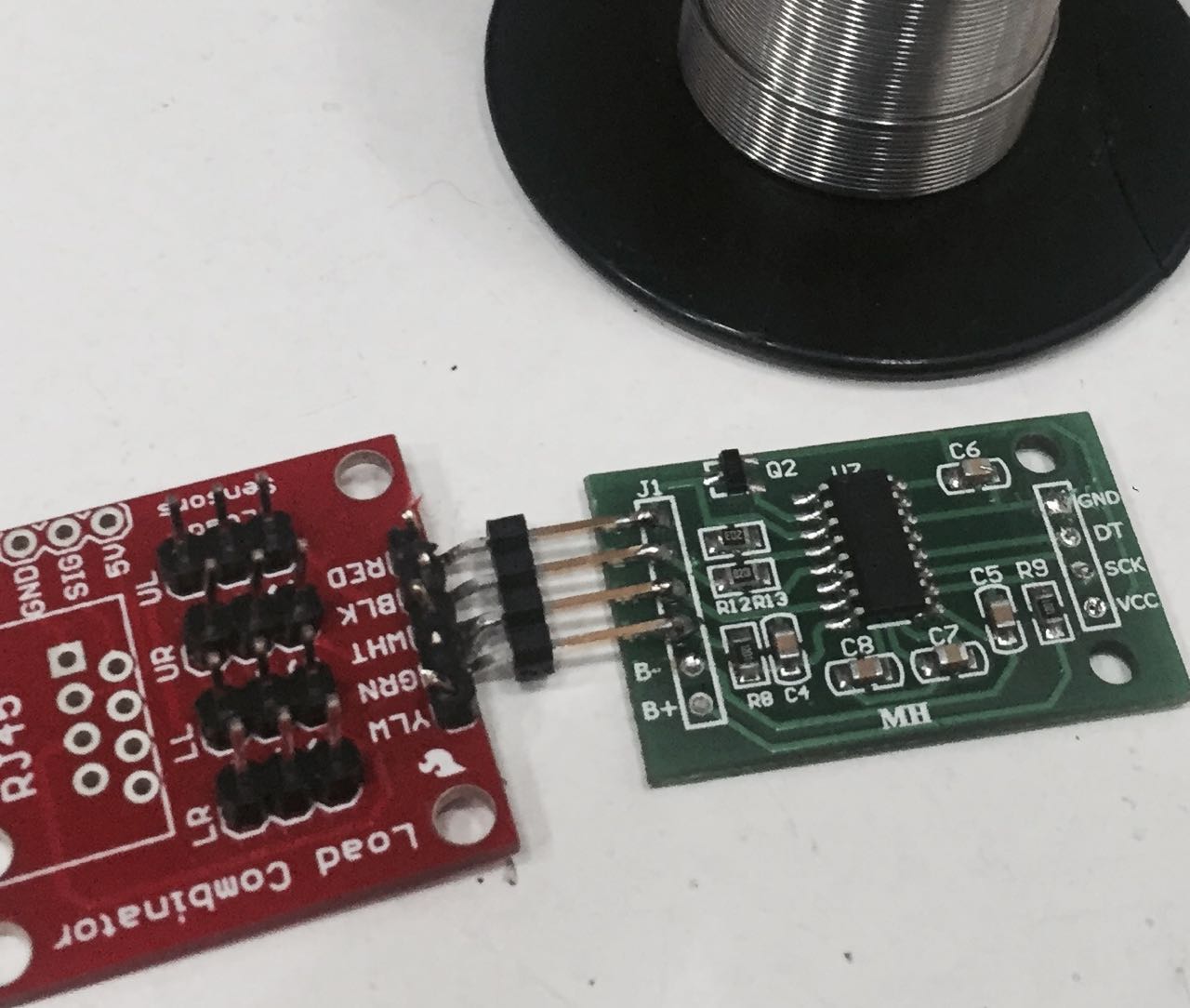
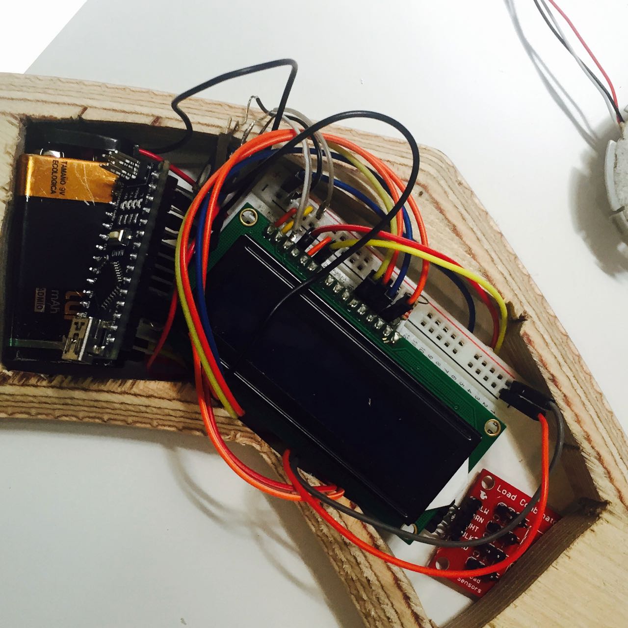
I try to combine the 4 3wires load cell using a wheatstone brigde configuration described above. However I was not sure I was making the right connection or it was just my cables that were not correctly soldered. To overcome this, and to be sure I was getting the value I wanted I source a load cell combinator from Sparkfun, that has the benefit of having a temperature sensor as well if I wanted to use to adjust calibration
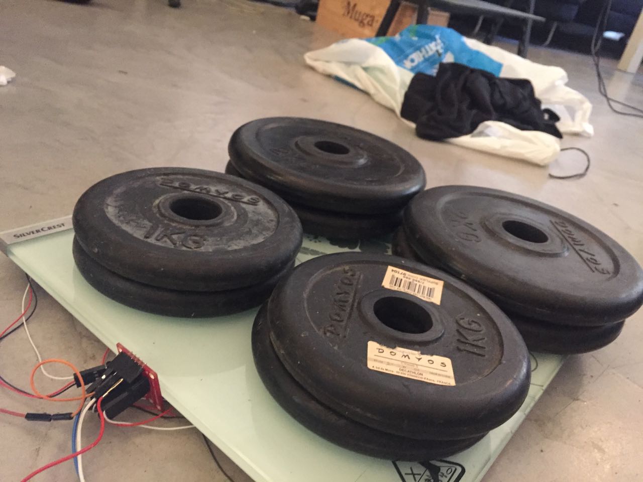
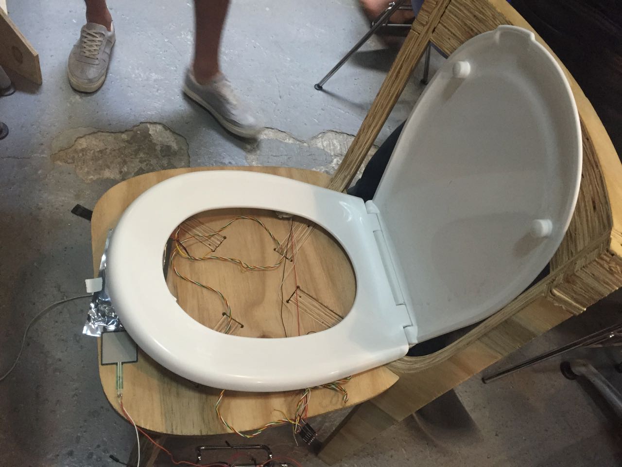
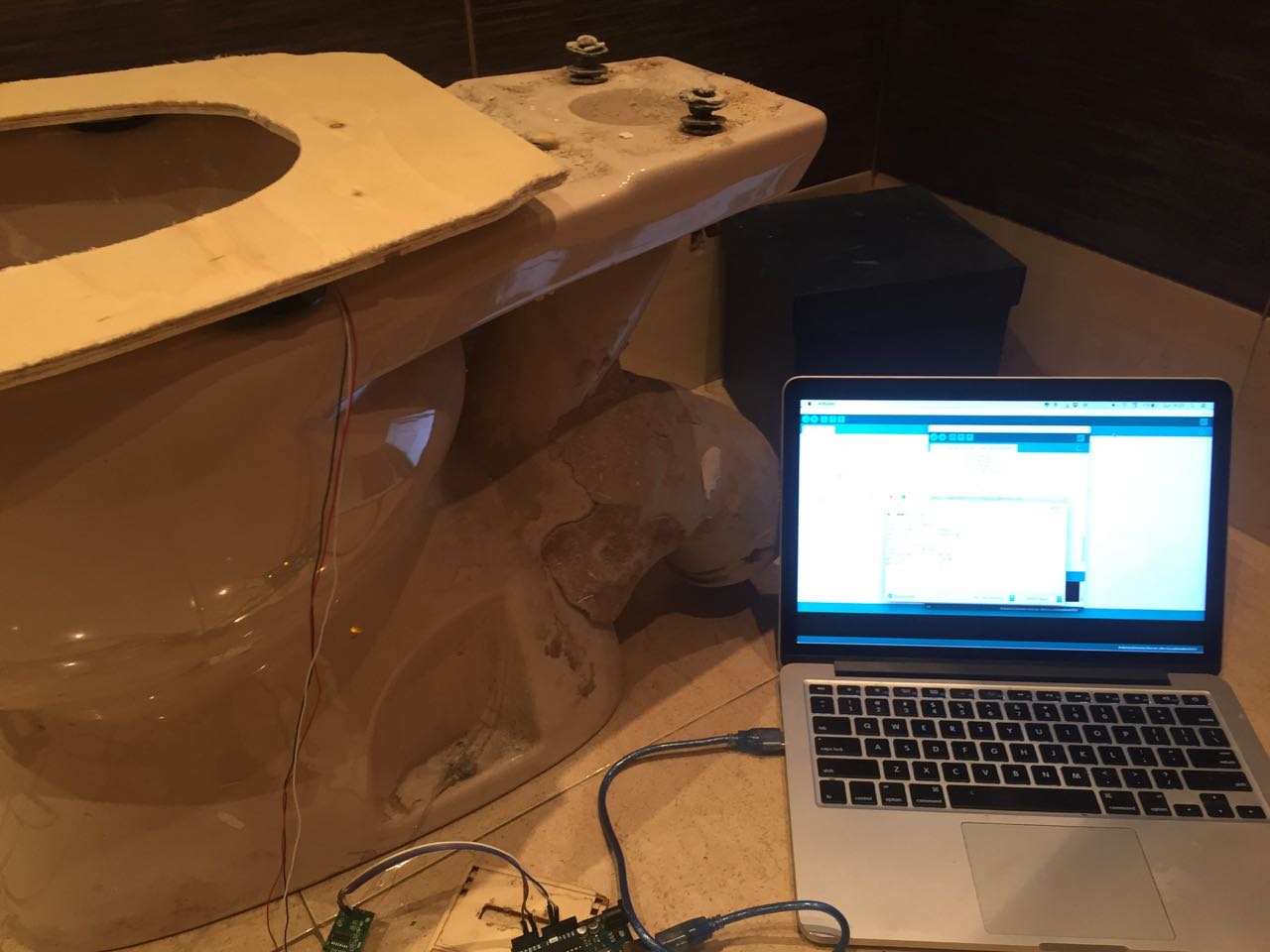
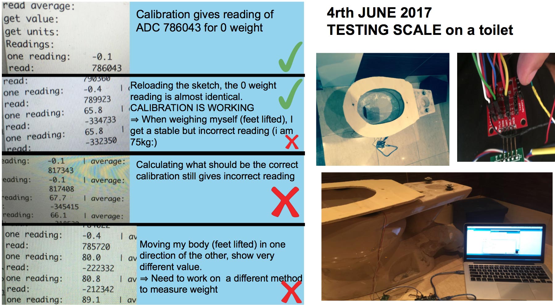
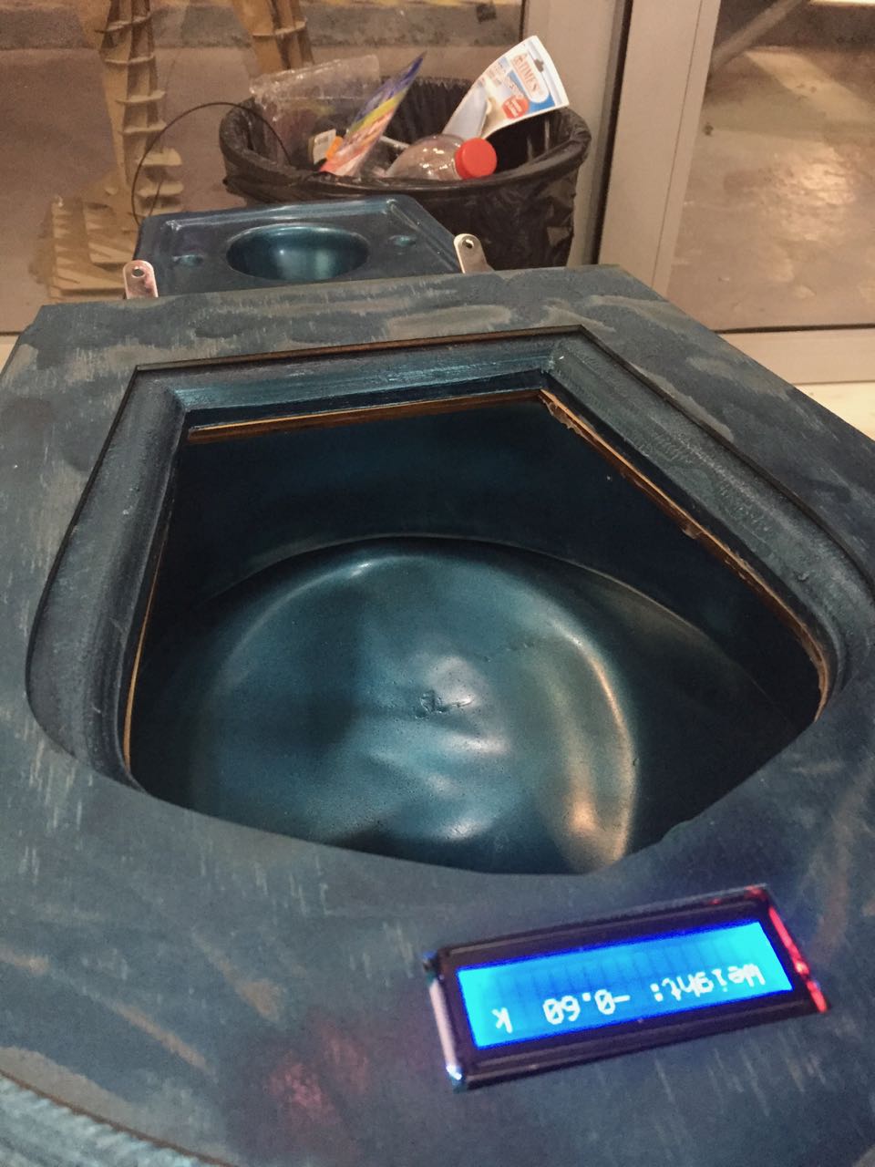
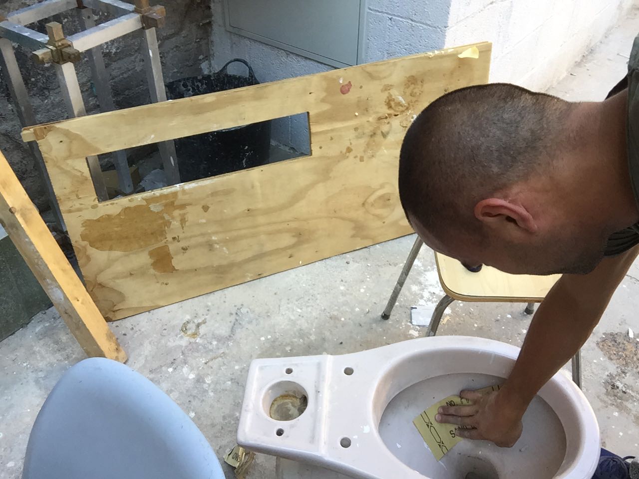
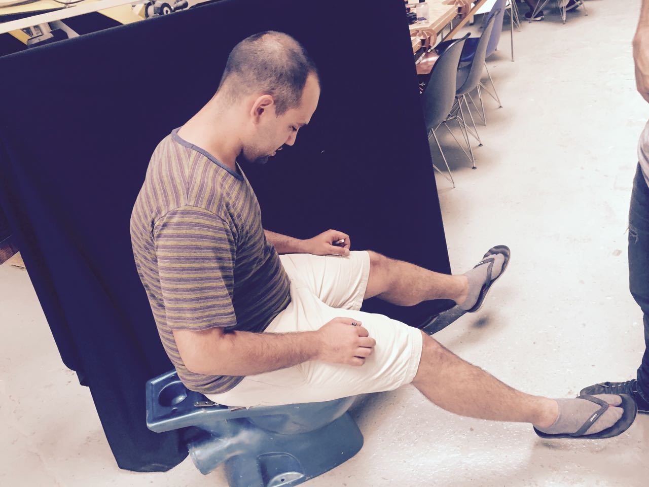
Live test on real Toilet
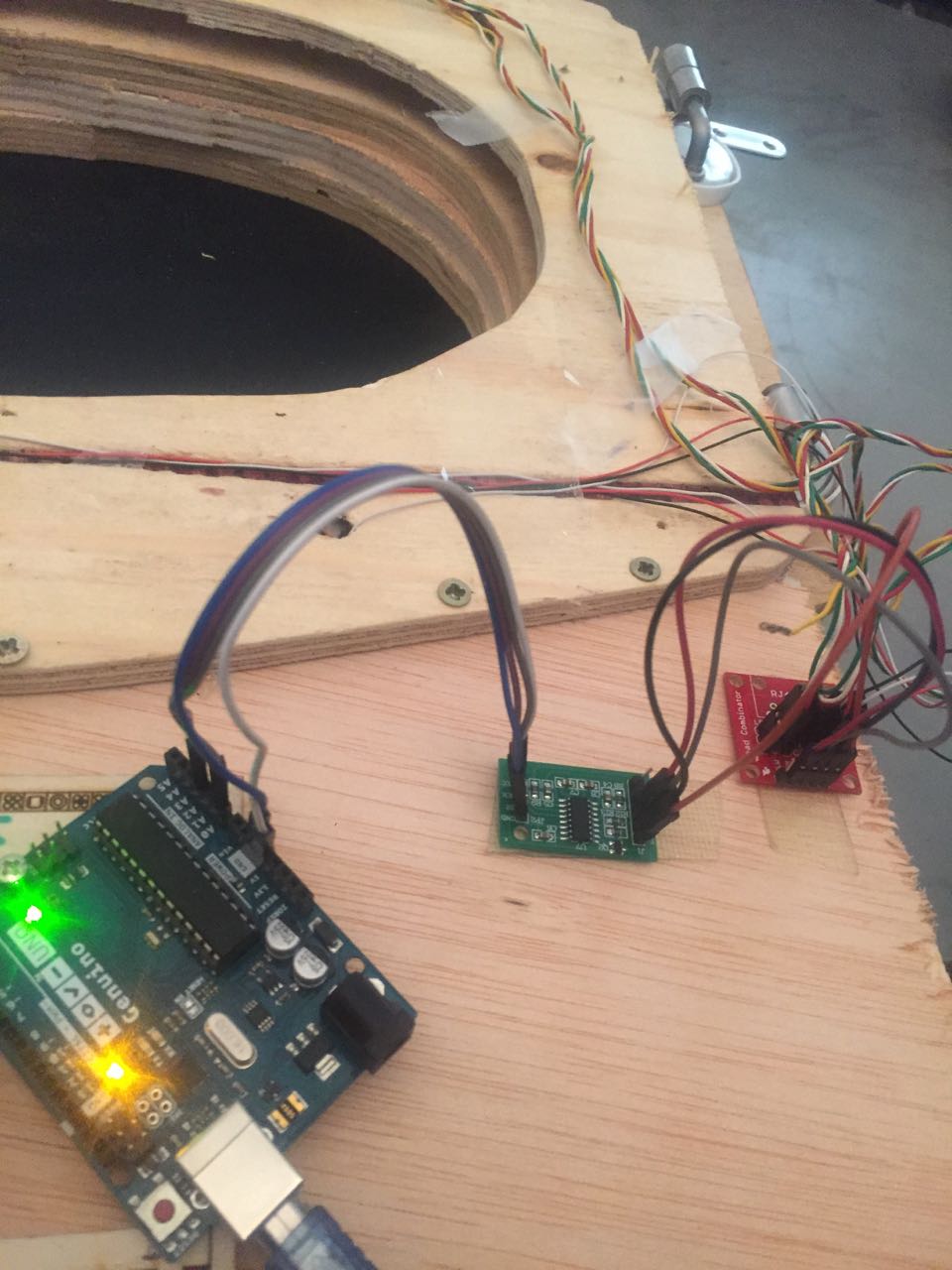
It took place at home, using the mockup toilet seat I made on the 4rth of June & some toilet (super heavy) i found in the street, i started to calibrate and test the 1st prototype. At this the whole electronics except the load cells obviously were stored outside the toilet seat
Mixed results
Yes I was happy I could calibrate the load cells and make the toilet seat work but this was retaviely unstable as I hads to redo the calibration everytime I was moving the toilet (not fixed to anything) slightly
Reading correct weight even if feet are on the ground. Is it possible?
I also looked at ways to measure weight without having to lift feet. I looked at at ways to measure where the weight of the body was leaning towards.
One method is to have 2 load cells (with 4 wires). One at the front of the toilet seat, one at the back. I would then measure the difference between the 2 load cells and deduce where the majority of the weight of the person is leaning towards, and estimate the correct weight by adding a multiplier corresponding to how our body lean. This solution could work if we all had the same body struture.
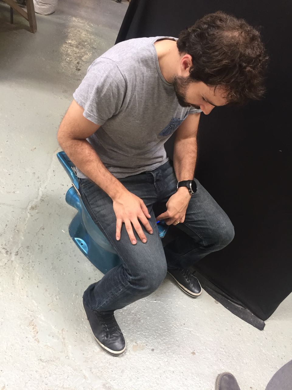
It is interesting to note that during those tests I could evaluate that in a standard seating common position, most people have 25% of their weight supported by their feet, the other 75% on their bottom
Another solution I looked at was pressure sensor at the end of end of the toilet seat to measure again the leaning of the user
At the end, given the time constraint, I decided to focus on making the prototype work, even though people would have to slightly lift their leggs to get the correct weight
I am not evaluating the cost of 3D filaments & machine usage here
Piece of wood from the fablab storage room I bought from another student: 20EUR
TOTAL
75 EUR
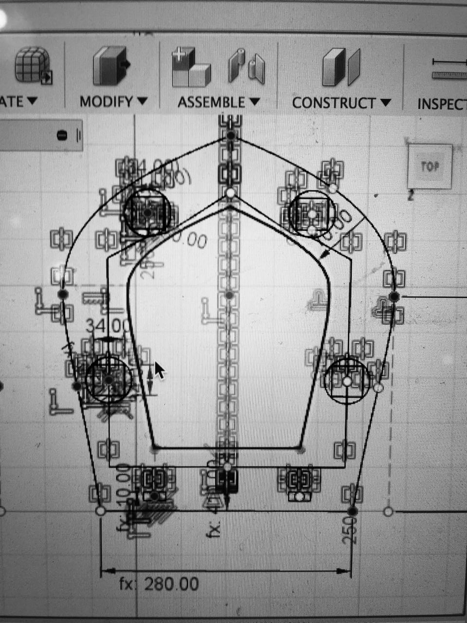
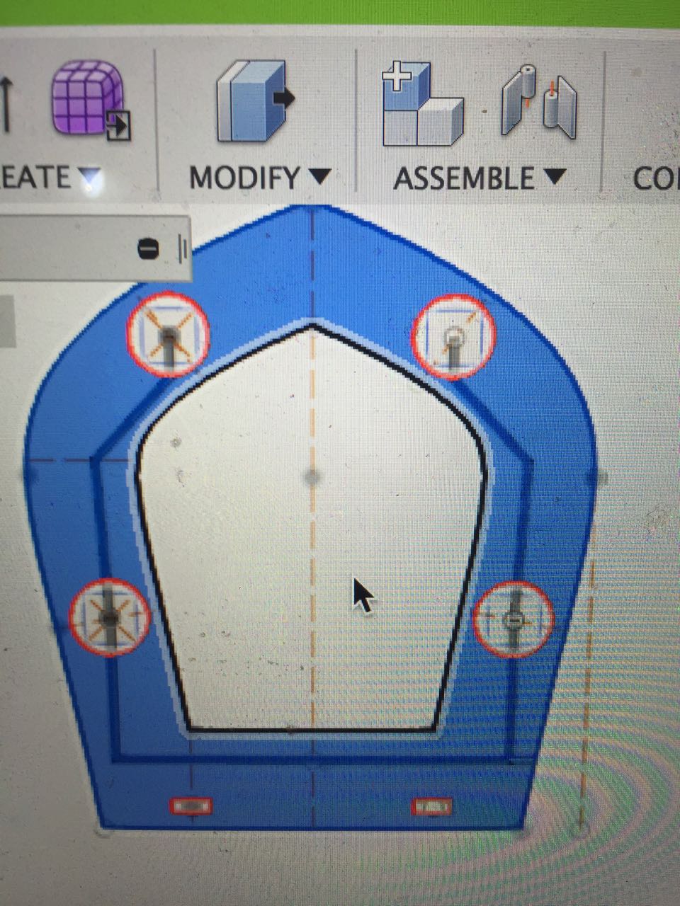
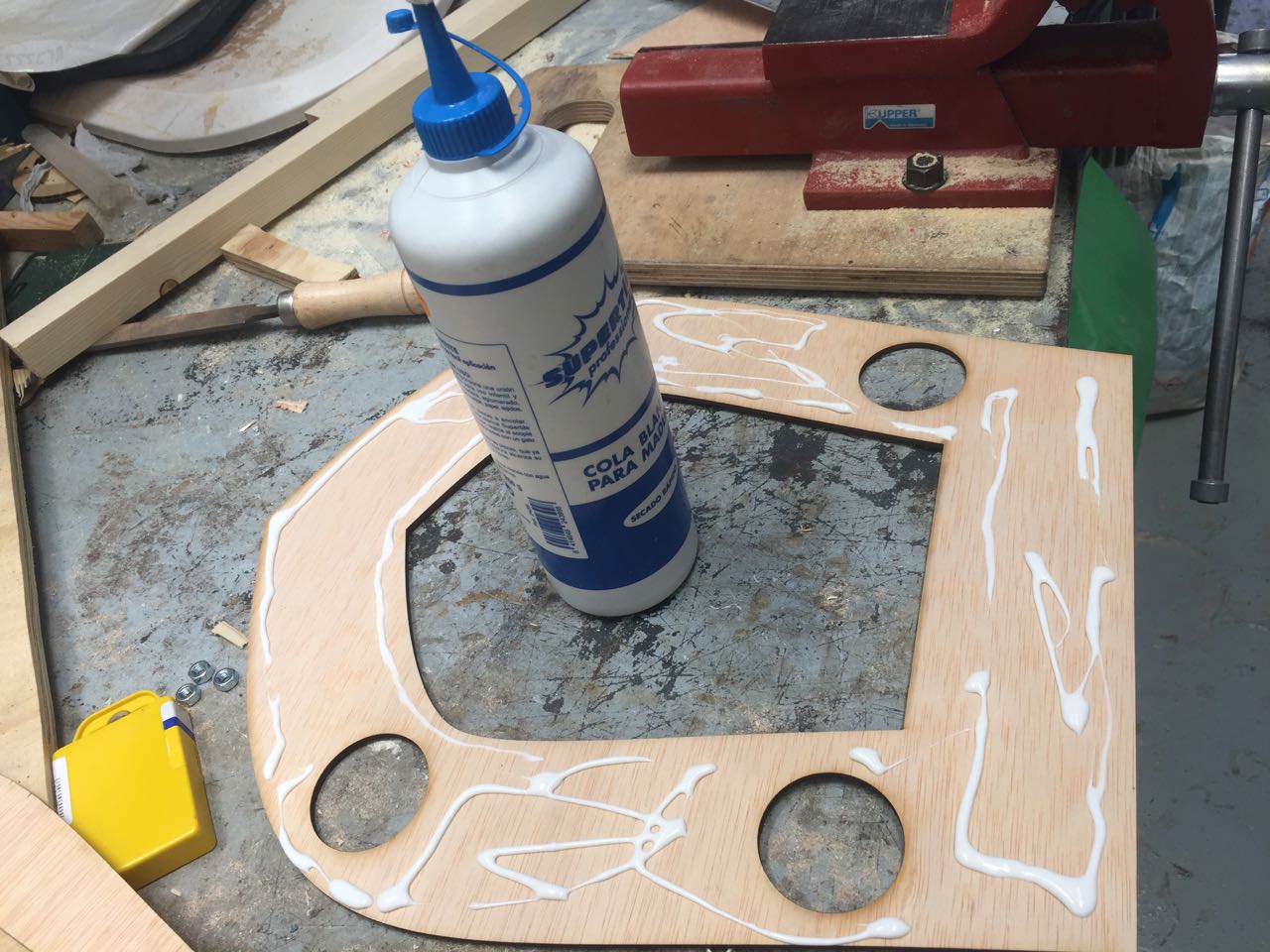
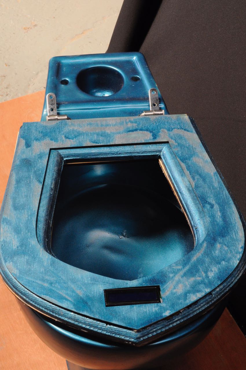
Making Toilet seat
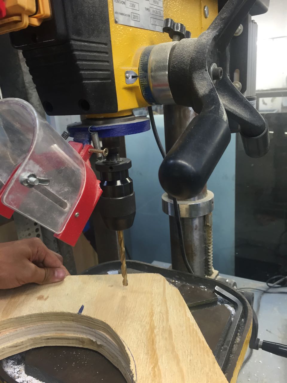
Milling the toilet seat: 6th June
I used CNC milling machine for my project (toilet seat scale), on 2 pieces of 10 and 20mm plywood (1 containing the electronics, the other being used as the seat itself )
Cnc millling a toilet seat
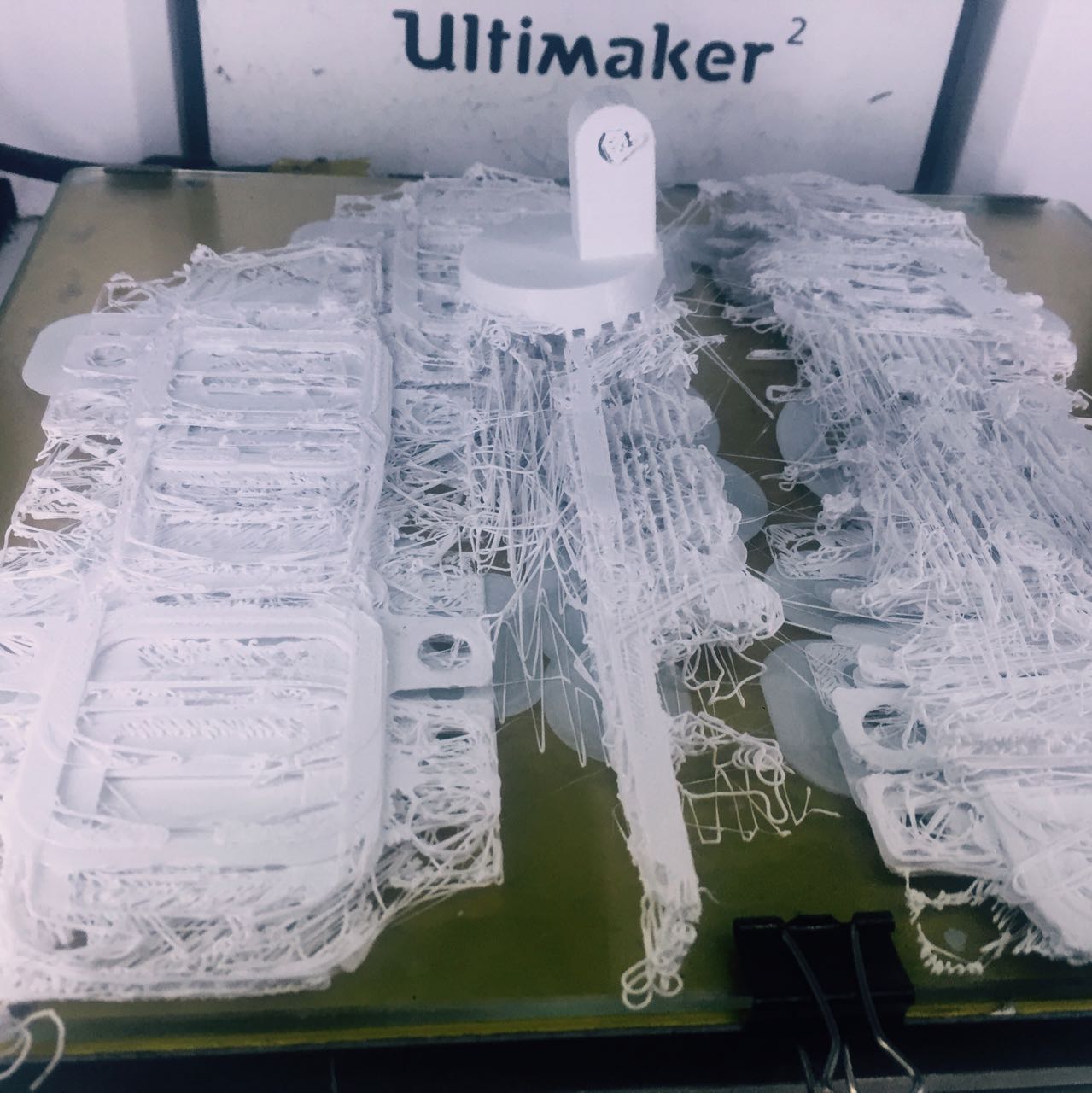
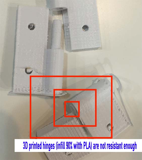
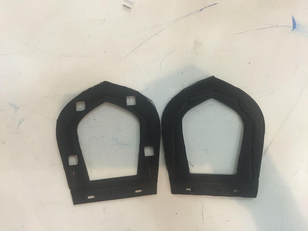
5rth June: 3D printing the hinges, gauge bracket, etc...
Here I downloaded the hinges in thingiverse. I had a number of failed 3D print but we got there at the end.
3D printing Hinges & loadcells support
I used existing 3D designs made by other person for my project. On thingiverse I downloaded the 3D files I would need for my prototype. I 3D printed them after. This was a big time saver.
15 seconds video showing 3D prints (click here if the video does not play)
At the end I did not use all the 3D printed components (gauge brackets & load cell coins not used). I also 3Dprinted small version of the toilet seat before miling
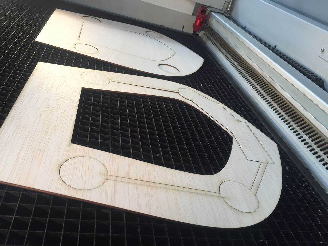
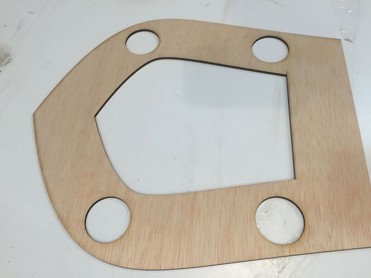
Lazer cutting the 2 bottom layers of the toilet seat
The toilet is comprised of 3 layer (top layer CNC milled 10mm wood), and the 2 middled layers Lazer cut 3mm plywood
Assembling
Programming
The whole programming of the toilet seat scale prototype has been done in Arduino IDE. You can find at the bottom of the page my attempt to replace the Arduino by a satshakit. Unfortunately I no longer have access to the Arduino sketch (see dowloadable file section for more info). However I can explain what the sketch was doing
In the set up, the sketch was running the calibration, using a multiplier which could be and had to be modified everytime the toilet seat was moved to a different location
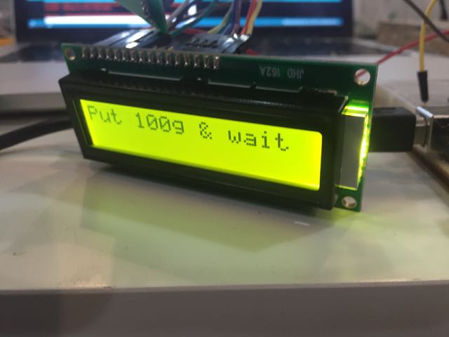
In the set up of the sketch were also placed all the instructions that were displayed on the LCD like "please seat down", "please lift your legs", "please wait"
The void loop was reading weight data
Averaging the last 10 values to return a weight in kilo
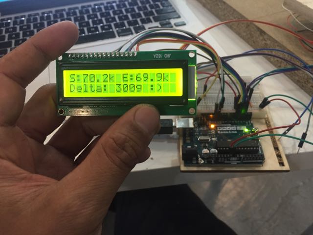
The sketch then displays this information on the LCD screen
It sounded relatively simple like this. However this was a relatively detailed script that was best suited (in terms of size) to be stored in a ATtiny Mega rather than an ATtiny 45/44
Calibration after assembly
User Testing
I was very very happy that afer a lot of time spent on calibrating the prototype, all the 5 users who tested the toilet (lifting their legs) had their correct weight displayed
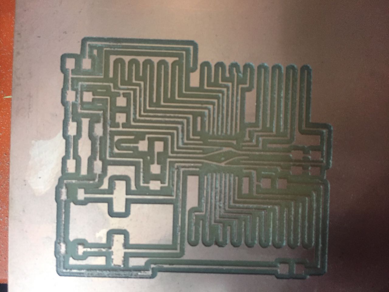
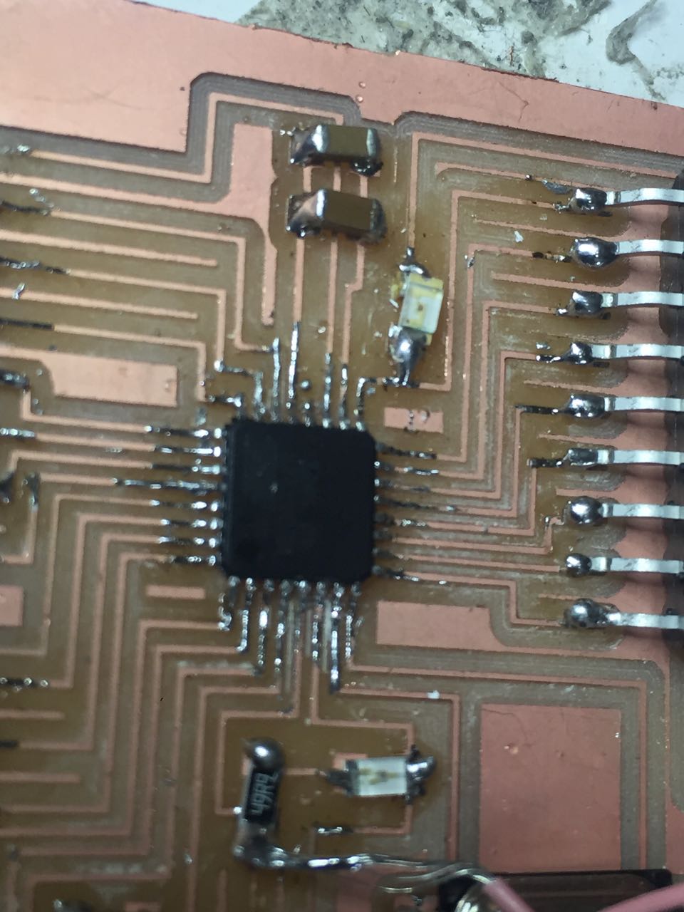
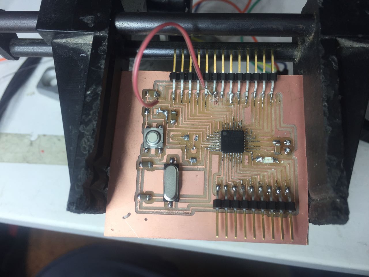
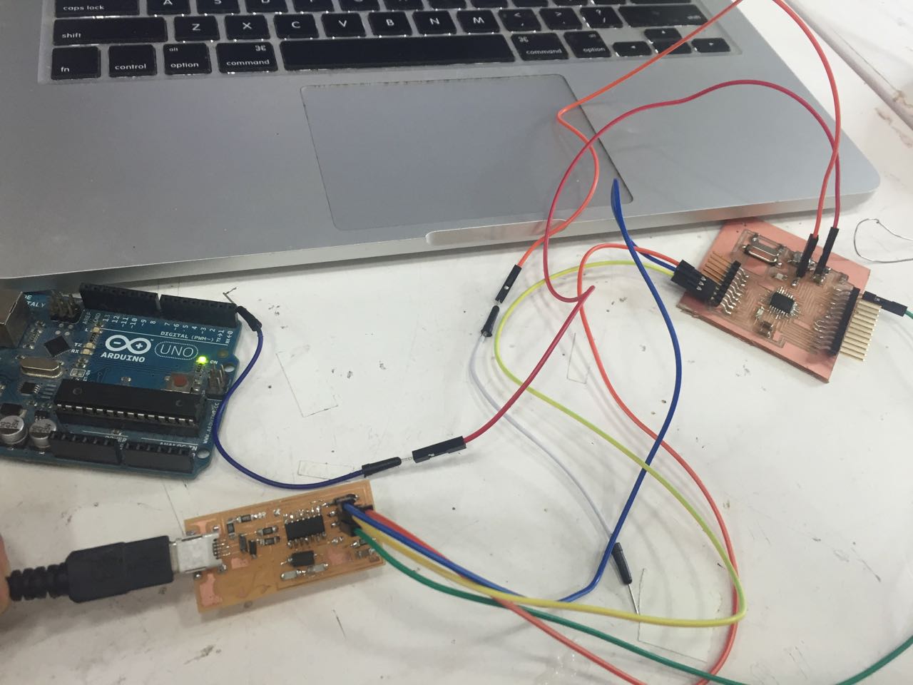
Replacing the Arduino Nano by the satshakit
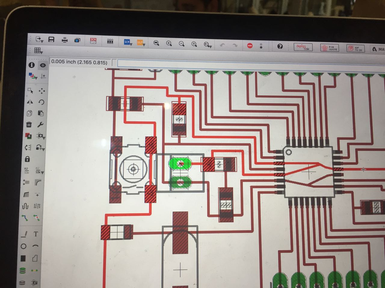
I am trying to replace the Arduino nano i am using in this project with a satshakit. I downloaded the eagle & tutorials file from (link here)
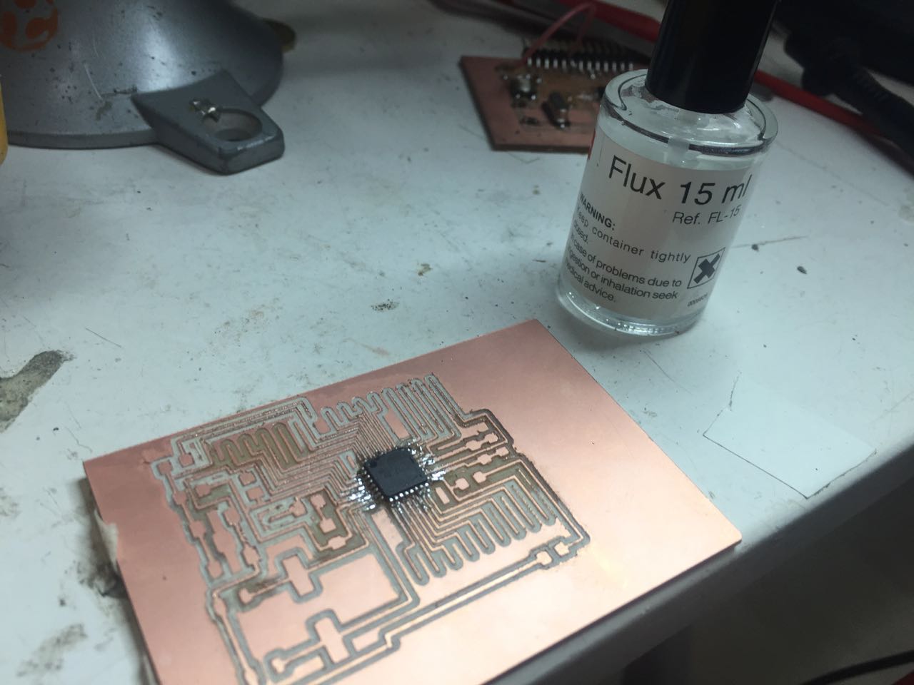
I initially soldered the ATtiny mega incorrectly to the board. I tried to fix it by using Flux. As it was not working, I took the ATtiny mega using the heat gun
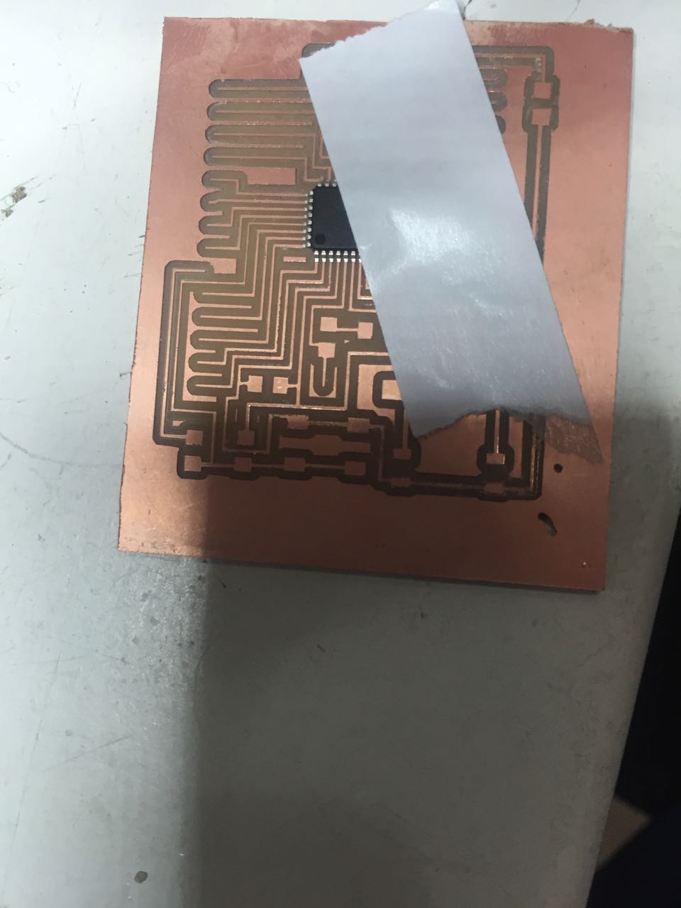
By placing a tape on on side of the microprocessor it makes it easier to solder
I used tape to place the ATtiny Mega in position on the board before soldering
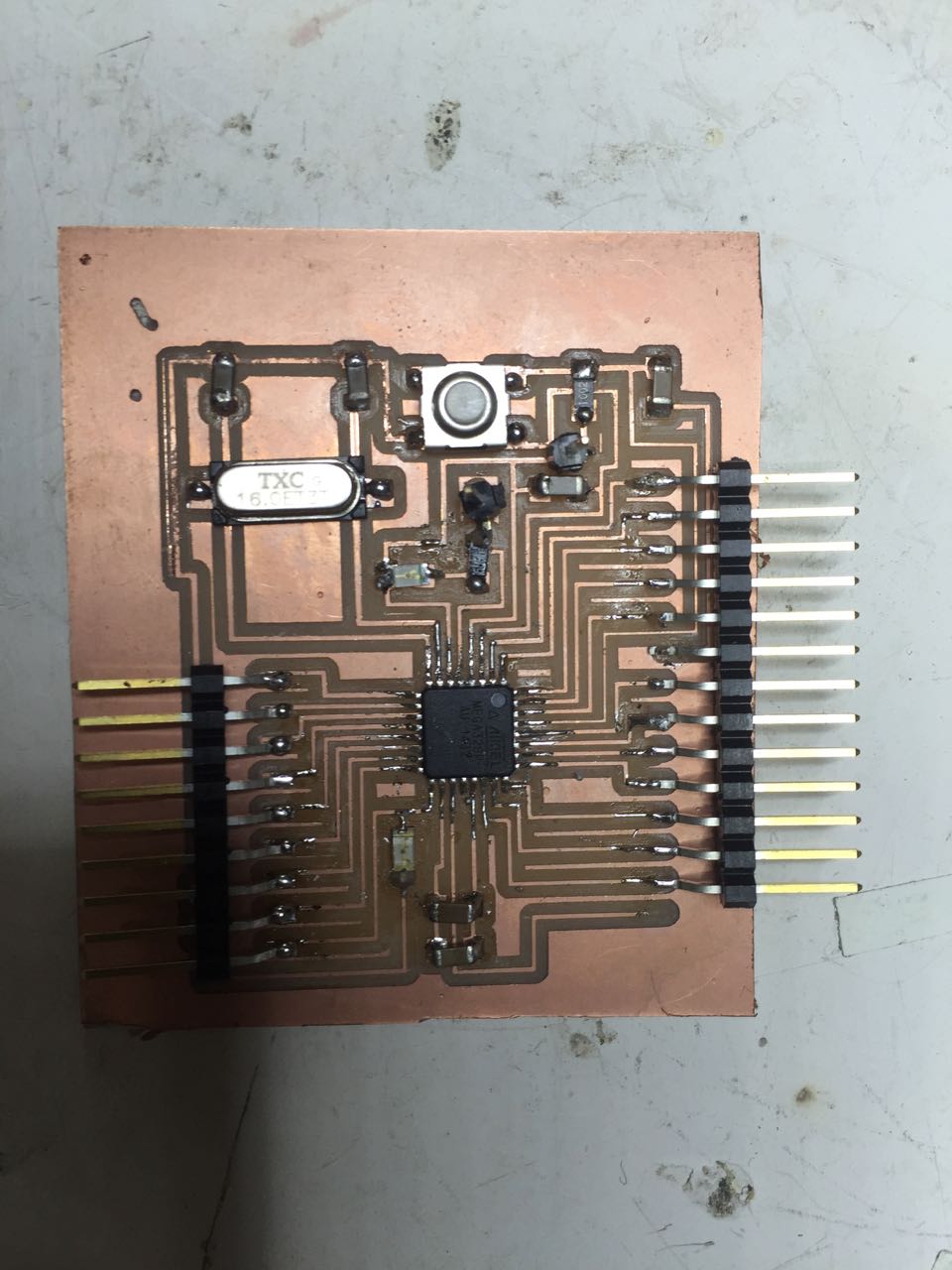
Final satshakit ready to be programmed
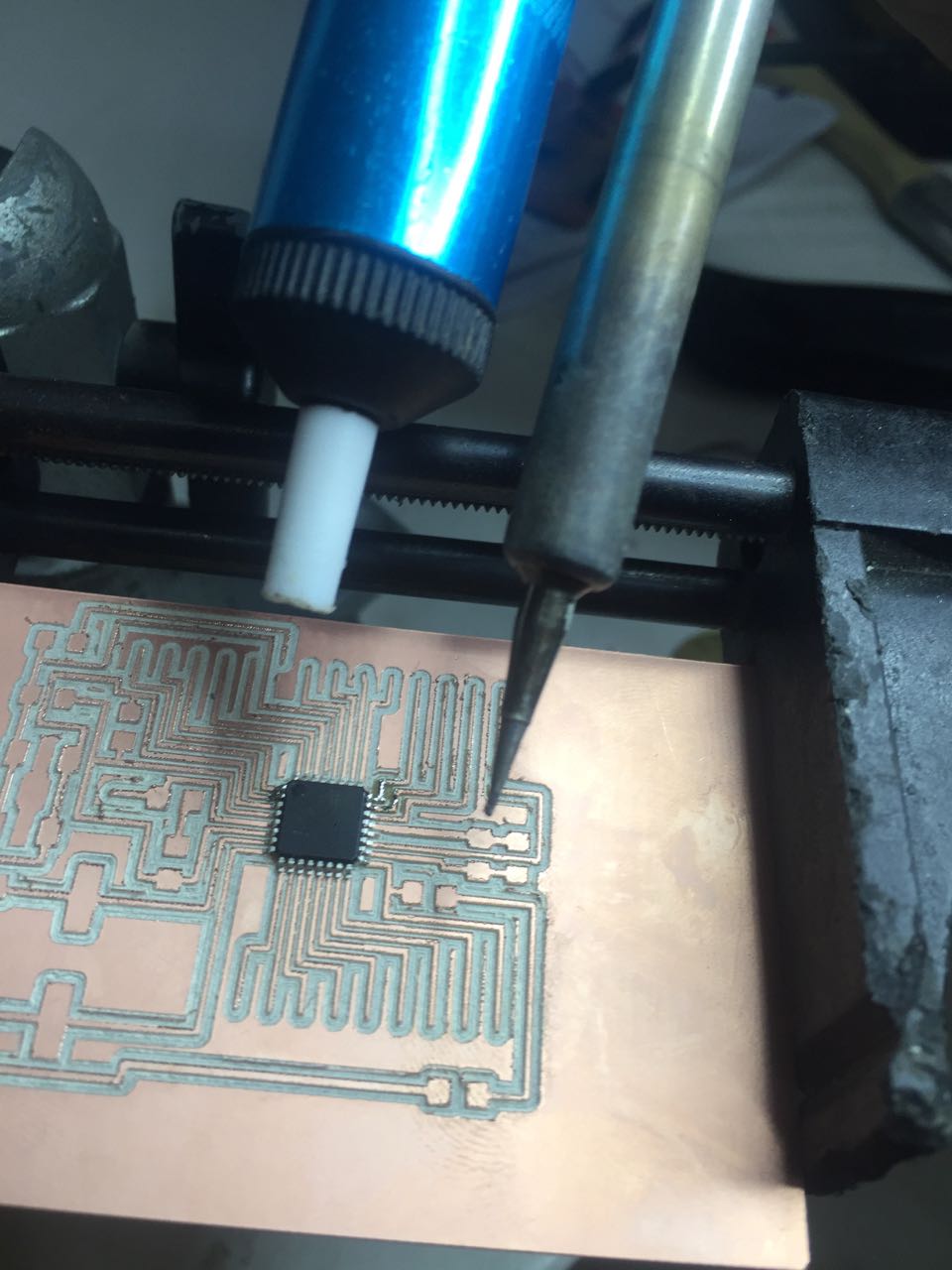
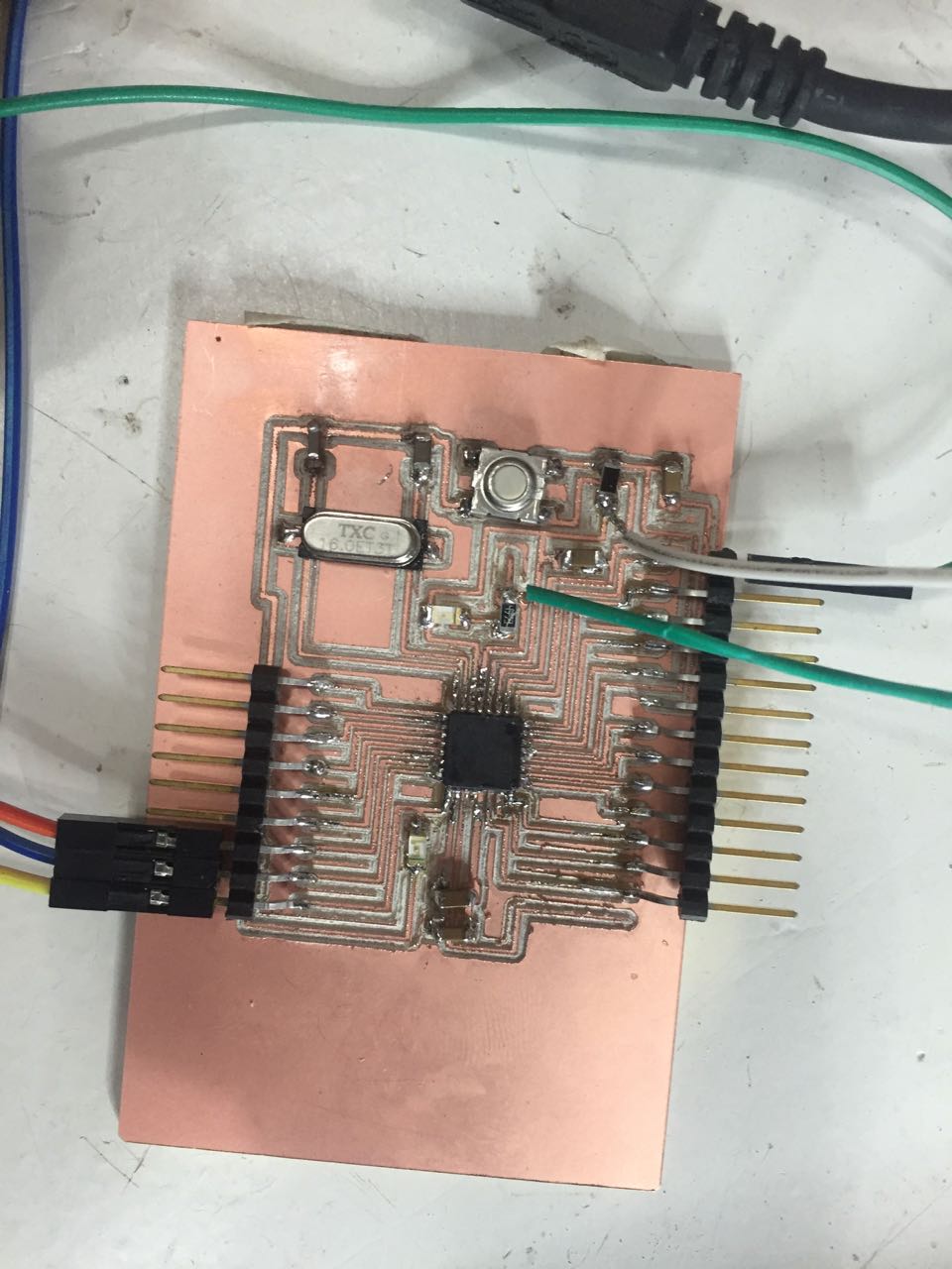
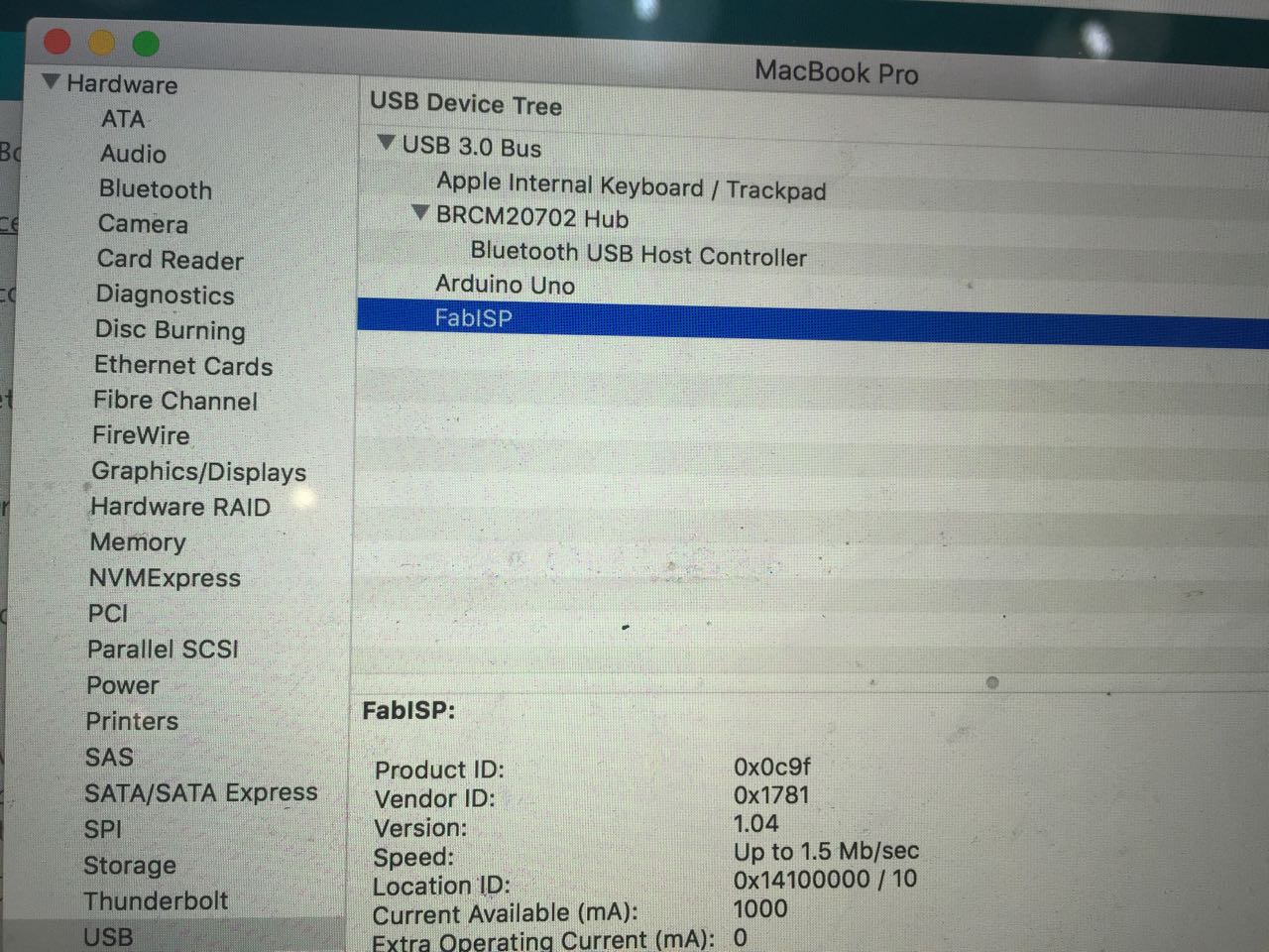
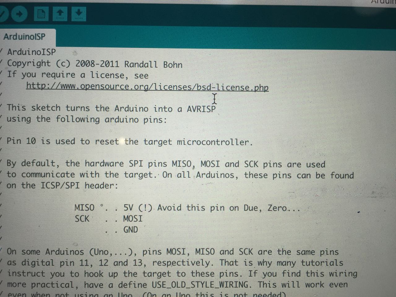
I used the Fab iSP of a classmate to program the Satshakit, using an arduino board to power 5V to the Satshakit
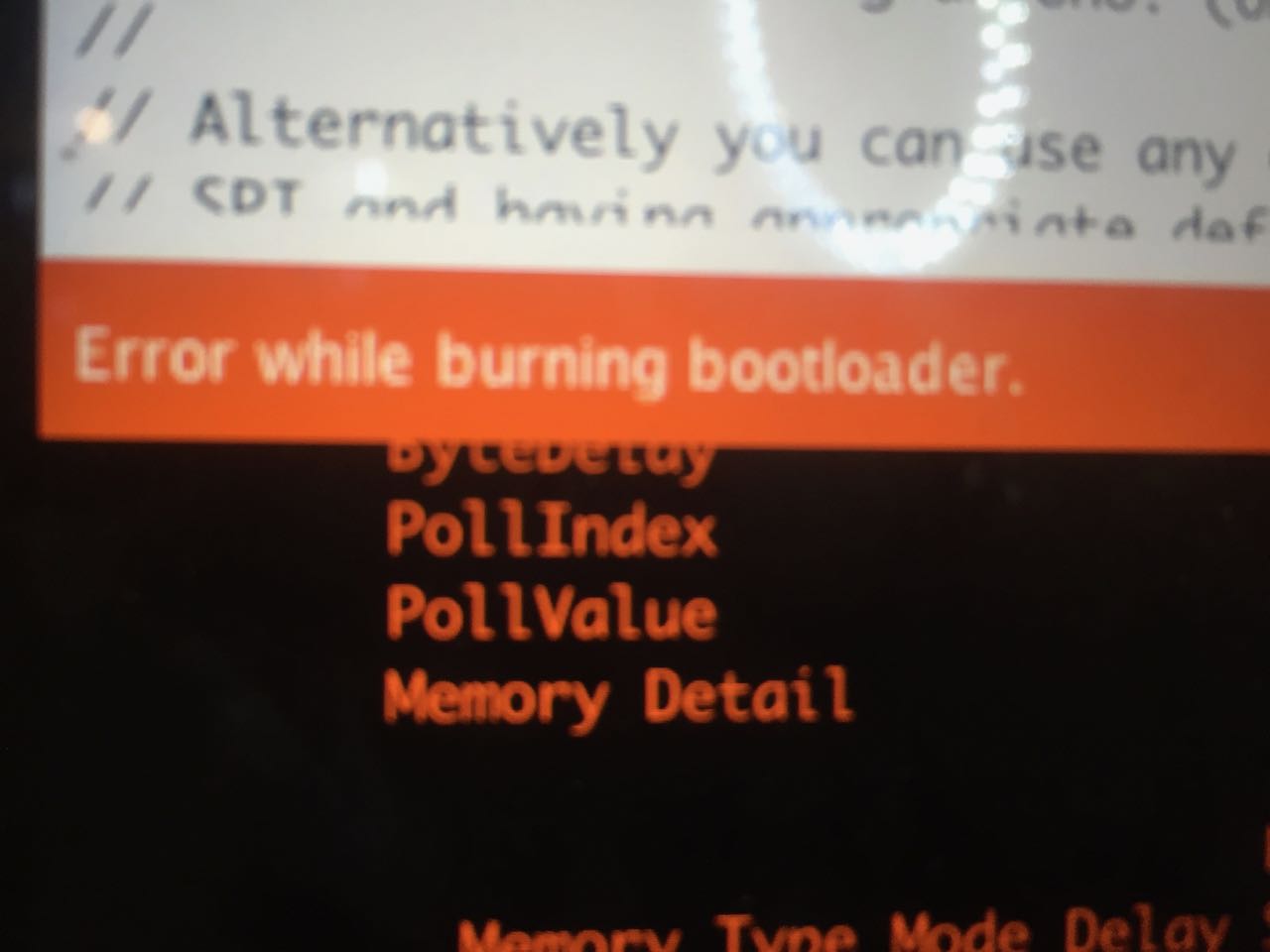
At the end of the process, I received an error message from the bootloader. I intially investigated the issue (focusing on eletric connection) without any success. I decided to park making of the satshakit for now and used an Arduino Nano for now to be ready for the final presentation, and maker faire of Barcelona.
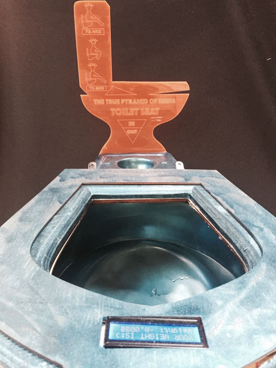
P6. GETTING READY FOR THE MAKER FAIRE
It was a really excting moment to see people trying the prototype
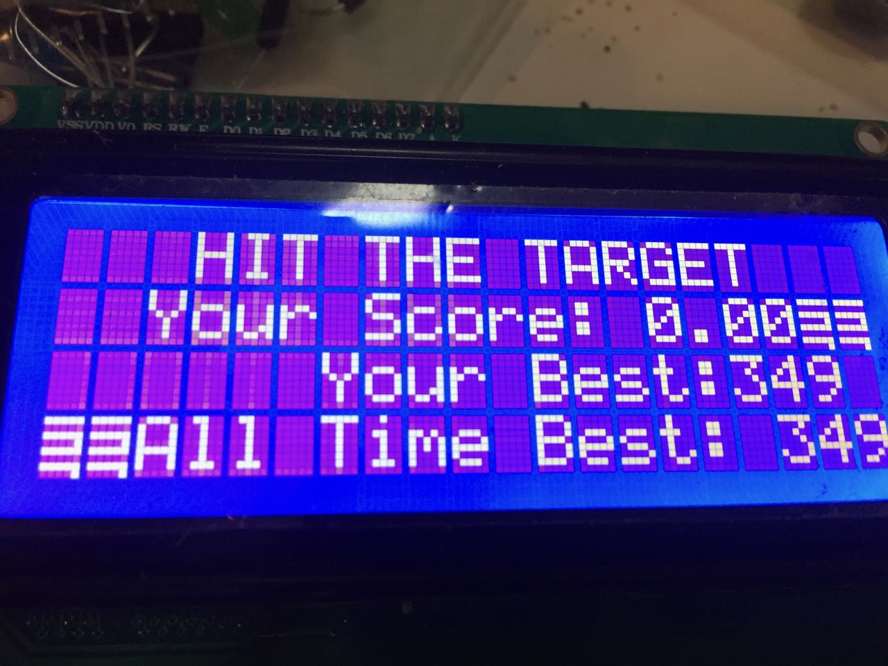
I signed up to the makerfaire barcelona 2017 only a few weeks before the faire. I was not sure I would be ready but I was really looking forward to have the chance to participate to a maker faire. I am very happy I could present my prototype to a bemused audience who were eager to try it, laugh about it, but not necessarly buy it:)
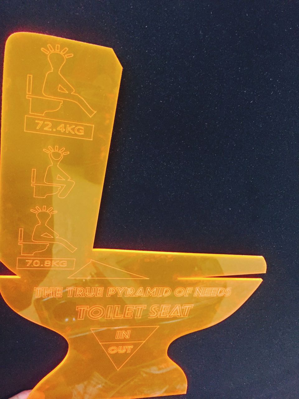
I designed and lazer cut in acrylic 3mm the below as funny instructions for the toilet seat scale
P7. DOWNLOADABLE FILES
What a nightmare !
Files for download
In June 2017, exactly a week after my final presentation, as I was updating my weekly assignements on my website, my mac laptop suddently stopped working. PANICK !!!. I went to the Apple Store. No way to save data. The hard drive was rebooted and all data deleted. Unfortunately for me, the apple icloud back up i had in place was only backing up photos and not files. I set my icloud backup incorrectly. I lost countless notes I took during the fabacademy. I had a folder for each week. All my Rhyno, Fusion, Arduino, Eagle files I did not push the githup were gone. Unfortunately, and I am too blame for this, I did not send all the files to github, especially in the last weeks and in particular for the project. So my DOWNLOADABLE FILES PRODUCT PAGES IS LIGHT