Output devices
Task to do-
Add an output device to a microcontroller board you've designed and program it to do something.
Add an output device to a microcontroller board you've designed and program it to do something.
Digital output-when any output device works by receiving zero and high voltage (0 & 1) from micro controller then it is called digital output.this device work by receiving on and off signals.example-led,bezzer
Analog output-when any output device works by receiving various value between zero to vcc from micro controller then it is called analog output.Communication devices are mainly analog
Analog output-when any output device works by receiving various value between zero to vcc from micro controller then it is called analog output.Communication devices are mainly analog
Work done-
In this assignment I have done 2 programs one is for my final project and second one is for 'making time laps machine' project
1.Idea about my output device
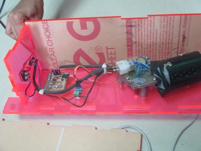
In assignment of lnput devices I used ACS715 Current sensing module . Now here for my basundi maker project I am going to add buzzer at the output side to notify the user about completion of activity.
Now I will use 12v dc motor for continuous stirrer processing. Current sensor will sense current drawn by motor and by that we will come to know about the load on motor.So when milk will reach to required thickness alarm will be blown.
Same like input device here I used Hello world board as a main unit. Inside this I used PIN PA0 is input pin and PA1 is output pins.You can see more about Hello world board here.
2. I used servo motor and stepper motor in time laps machine and programmed it in arduino
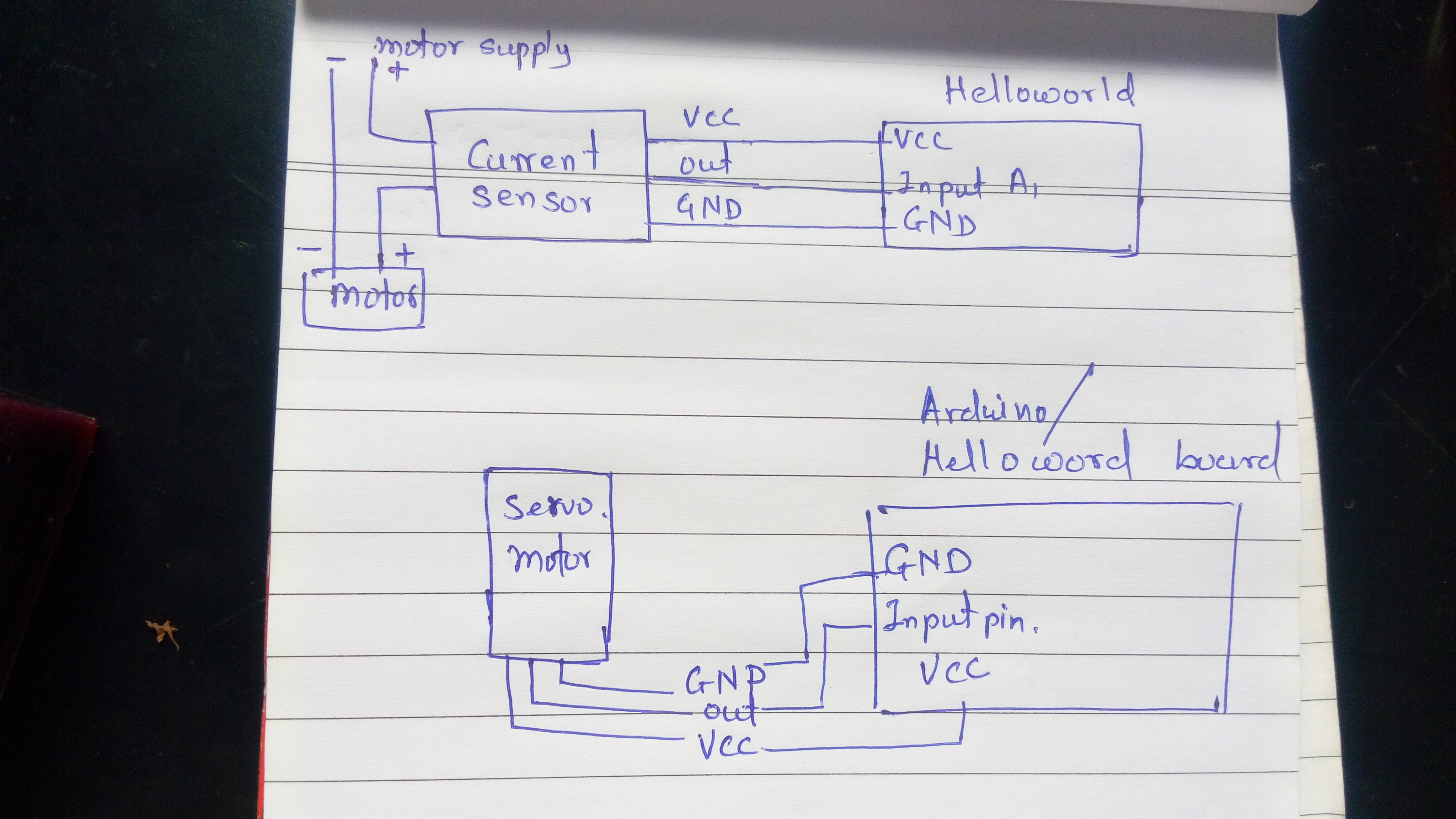
Circuit Description :
Here inside circuit diagram I used PORT A as a input as well as output port. At the input side I have connected current sensor and at the output side there is buzzer. In hello world board schematic PIN A1 is output pin for buzzer.
logic
I am reading to current sensor.So it is providing analog values to controller.As load on motor increases while stirring then values given by current sensor changes.When we reach to required load value we get from current sensor on serial monitor is near to "apm=4" So I have set the range and giving buzzer when we get that range.
So out put device I have used is Buzzer.
Please refer this for detail
I made connections for output 1 and 2 as below
 2. Time laps
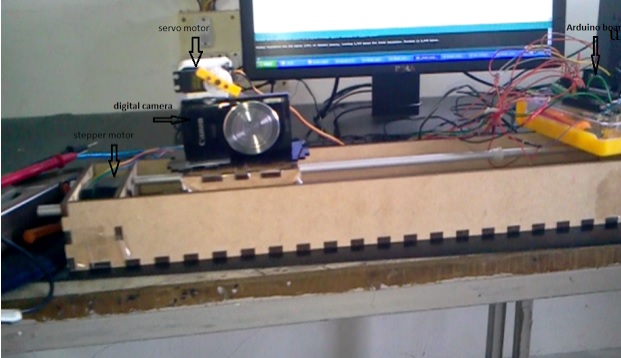
This is a small project in which I used first stage of make a machine.This stage was made by my seniors and I made it functional by using it for clicking a photo after some time interval.I mounted camera on axis of stepper motor so it moves along single axis.I have mounted servo motor on camera which turn on camera and clicks picture.
I have made program in arduino IDE for time laps .I used servo motor and stepper motor as a output device as below
For seeing the function of this machine refer this video.
In this assignment I used different motors,a simple buzzer and learn how to send signals from microcontroller to any device.While chosing output device we have to see its specifications,We have to see for its voltage and current requirement,We have to see that whether it is able to read our signal from microcontroller or not.These all things I learned and experienced in output device assignment
You can download all programs for output here
Download eagle files for board I used (edited hello world)
Download eagle files for output board
Download output board png
In this assignment I have done 2 programs one is for my final project and second one is for 'making time laps machine' project
1.Idea about my output device
In assignment of lnput devices I used ACS715 Current sensing module . Now here for my basundi maker project I am going to add buzzer at the output side to notify the user about completion of activity.
Now I will use 12v dc motor for continuous stirrer processing. Current sensor will sense current drawn by motor and by that we will come to know about the load on motor.So when milk will reach to required thickness alarm will be blown.
Same like input device here I used Hello world board as a main unit. Inside this I used PIN PA0 is input pin and PA1 is output pins.You can see more about Hello world board here.
2. I used servo motor and stepper motor in time laps machine and programmed it in arduino
Circuit Description :
Here inside circuit diagram I used PORT A as a input as well as output port. At the input side I have connected current sensor and at the output side there is buzzer. In hello world board schematic PIN A1 is output pin for buzzer.
logic
I am reading to current sensor.So it is providing analog values to controller.As load on motor increases while stirring then values given by current sensor changes.When we reach to required load value we get from current sensor on serial monitor is near to "apm=4" So I have set the range and giving buzzer when we get that range.
So out put device I have used is Buzzer.
Please refer this for detail
I made connections for output 1 and 2 as below
This is a small project in which I used first stage of make a machine.This stage was made by my seniors and I made it functional by using it for clicking a photo after some time interval.I mounted camera on axis of stepper motor so it moves along single axis.I have mounted servo motor on camera which turn on camera and clicks picture.
I have made program in arduino IDE for time laps .I used servo motor and stepper motor as a output device as below
For seeing the function of this machine refer this video.
In this assignment I used different motors,a simple buzzer and learn how to send signals from microcontroller to any device.While chosing output device we have to see its specifications,We have to see for its voltage and current requirement,We have to see that whether it is able to read our signal from microcontroller or not.These all things I learned and experienced in output device assignment
You can download all programs for output here
Download eagle files for board I used (edited hello world)
Download eagle files for output board
Download output board png