Embedded programming
Assignment for this week
- read a microcontroller data sheet
- program your board to do something, with as many different programming languages and programming environments as possible
- Link to this week’s home work page
This page is organized as follows:
- >Reading the datasheet
- Installing an AVR-gcc toochain on mac
- ISP programming with an arduino
- Failures with the FabISP
- Success with Hello board and ArduinoISP
Reading the datasheet
I read the datasheet, 286 pages ! The parts on registers, stack, data bus reminded me of an old time when I first started to learn Basic then assembly on my Amstrad CPC6128 which had a Z80 microprocessor. I must have been 12 years old and at that time, assembly was almost the only way to create fast animations of sprites for games. Then I went to high school, college, learned C, python, R and forgot almost everything about microprocessors until recently when I started to come back to it through the Arduino dev boards.

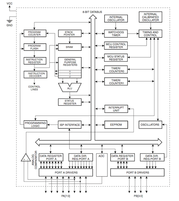
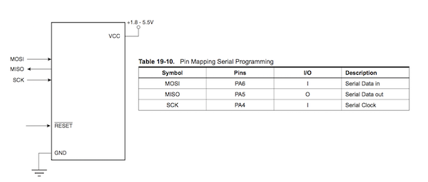
The ATTiny44 is a 8-bit microcontroller with 4K of In-System Flash Program Memory and 256 Bytes of In-System Programmable EEPROM. It has one 8 bit counter and one 16 bit timer/counter, a 10 bit ADC (Analog to Digital Converter) that can be used to read the value of a sensor for instance, and a universal serial interface with which one can communicate. In particular, it is possible to do In-Sytem Programming via the SPI port. Operating voltage between 1.8V and 5.5V.
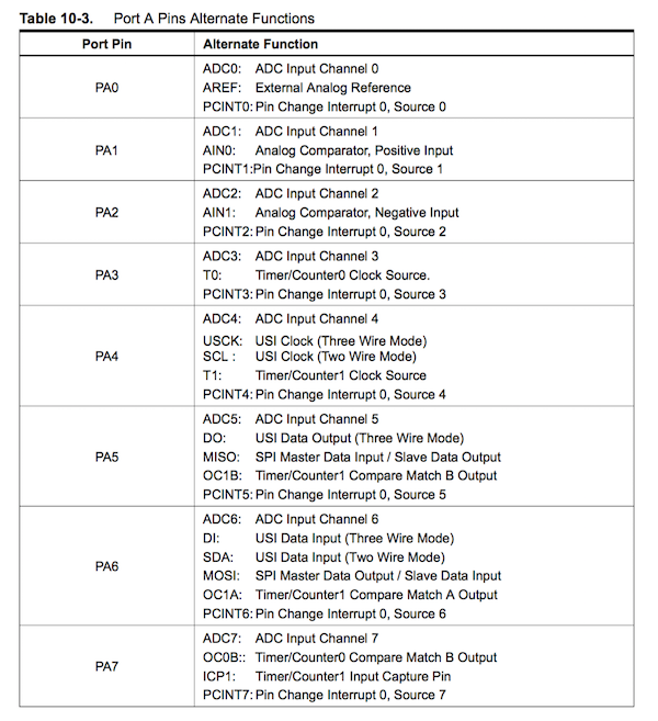
The ATTiny44 has 2 main ports (A and B) plus two pins for power supply Vcc and ground GND.Port A has 8 pins while Port B has 4 pins. Pins A4, A5, A6 and B3 are used for SPI communication (SCK, MISO, MOSI, RST).
Section 4 describes the CPU core architecture with the 32 8-bits general purpose working registers that can be used by the Arithmetic Logic Unit (ALU). Typically, as explained page 8, two operands are output from the Register File, then the operation (artithmetic or logic between registers or between a register and a constant) is executed and finally the result is stored back in the Register File (in one clock cycle). The program flow is provided by conditionnal or unconditionnal jumps and call instructions. During such a call or interrupt, the return adress Program Counter (PC) is stored on the Stack. Another important tool in assembly programming is the Status Registers that contains information about the result of an operation. Section 6 describes the Clock system. More interesting from a pratical point of view is the section 10 that describes the I/O ports with example code for reading a port (page 57). There we can learn two ways to read a I/O port (assembly and C).
In assembly
...
; Define pull-ups and set outputs high
; Define directions for port pins
ldi r16,(1<<PA4)|(1<<PA1)|(1<<PA0)
ldi r17,(1<<DDA3)|(1<<DDA2)|(1<<DDA1)|(1<<DDA0)
out PORTA,r16
out DDRA,r17
; Insert nop for synchronization nop
; Read port pins
in r16,PINA
...
In C
unsigned char i;
...
/* Define pull-ups and set outputs high */
/* Define directions for port pins */
PORTA = (1<<PA4)|(1<<PA1)|(1<<PA0);
DDRA = (1<<DDA3)|(1<<DDA2)|(1<<DDA1)|(1<<DDA0); /* Insert nop for synchronization*/
_NOP();
/* Read port pins */ i = PINA;
...
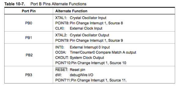
Pages 60 and 64 summarizes the functions of the differents pins of Port A
Section 11 and 12 describe the 8-bits and 16-bits Timer/Counter operation. Again more important from the practical point of view is section 14 that describes the Universal Serial Interface (USI) with the 2 wires and 3 wires data transfer modes. For the 3 wires mode, pin names are denoted DI, DO and USCK (compatible with SPI). Examples are given. This may be interesting to implement SPI on an analog sensor by coupling it with a microcontroller. In the 2 wires mode, pins are denoted SCL and SDA. Clock generation must be implemented in the software. Section 16 describes the use of the Analog to Digital Converter (ADC). Section 19 (Memory Programming) describes the different methods for programming the memory of the ATTiny (page 159). Page 162 describes serial programming. RESET must be pulled to GND.
The Serial Programming Algorithm is given at section 19.5.1 (page 163) and finally, section 20 gives the electrical characteristics.
In conclusion, I think that probably all the useful information for working with the ATTiny44 are present in this datasheet but the datasheet in itself does not teach you how to use the ATTiny. Instead application notes or tutorials are required if one wants to use the ATTiny.
Installing an AVR-gcc toochain on mac
I installed CrossPack that is a development environment for Atmel’s AVR microcontrollers running on Apple’s Mac OS X, similar to AVR Studio on Windows. Crosspack consists of the GNU compiler suite, a C library for the AVR, the AVRDUDE uploader.
ISP programming with an arduino
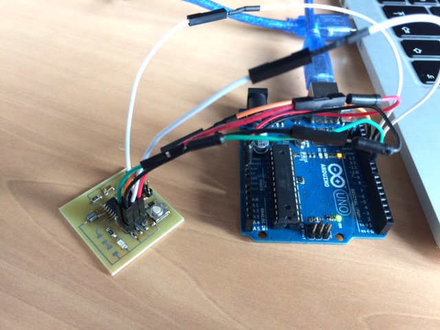
Since I had to wait to get the electronic components to finish the FabISP and Hello boarfd, I decided to train with an DIP8 ATTiny13 which was available in my lab and to use an ARDUINO Uno as a ISP programmer. In order to use the ARDUINO programmer as a ISP programmer it is necessary to upload the ArduinoISP Example on the Uno and change the BaudRate to 9600.
The ATTiny13 is extremely simple, it has 8 pins. 4 pins are used for ISP programming, 2 pins are used for Vcc and GND. This means 2 pins PB3 and PB4 can be used to blink a LED for instance. I connected a LED in series with a 470 ohm resistor between PB3 and GND.
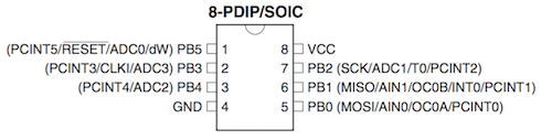
On the ARDUINO Uno, the ISP pinout is the following:
- MOSI: Pin 11 to be connected to PB0 (MOSI)
- MISO: Pin 12 to be connected to PB1 (MISO)
- SCK: Pin 13 to be connected to PB2 (SCK)
- SS: Pin 10 to be connected to PB5 (RESET)
I also connected the VCC and GND and I used this link to upload a blink on the ATTiny13. The code is the following:
#include <avr/io.h>
#include <util/delay.h>

int main(void)
{
  DDRB = 1<<3 // port B3, ATtiny13a pin 2
  PORTB = 0x0;

  while (1)
  {
    PORTB = 1<<3; // port B3, ATtiny13a pin 2
    _delay_ms(500);
    PORTB = 0X0;
    _delay_ms(250);
  }
}
To compile I used the following commands in a terminal:
avr-gcc -g -DF_CPU=9600000 -Wall -Os -mmcu=attiny13a -c -o tmp.o blink.cpp
avr-gcc -g -DF_CPU=9600000 -Wall -Os -mmcu=attiny13a -o tmp.elf tmp.o
avr-size tmp.elf
avr-objcopy -j .text -j .data -O ihex tmp.elf tmp.hex
Then program fuse and program upload
avrdude -p attiny13 -P XXX -c stk500v1  -b 9600 -q -U lfuse:w:0x7a:m -U hfuse:w:0xff:m

avrdude -p attiny13 -c stk500v1 -P XXX -b 9600 -q -U flash:w:tmp.hex
with XXX replaced by /dev/cu.usbmodem1421 which is the COM port of the Uno.
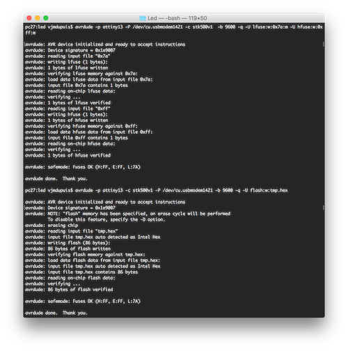
and I was happy to see the LED blink !
Failures with the FabISP
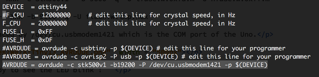
Since the electronic components have finally arrived, I made two FabISPs: one based on Anna Kaziunas' design and one based on David Mellis' design.
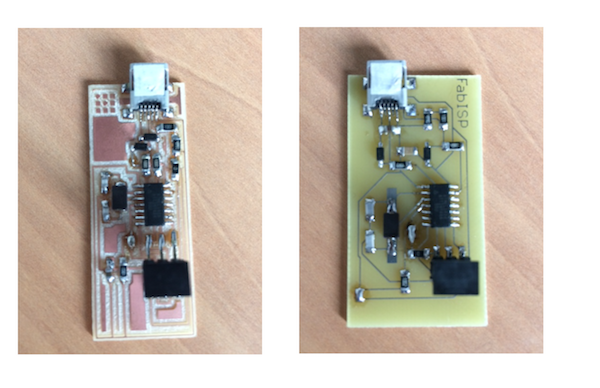
I carefully checked that the boards. No shorts and each pin is connected to what it should be. Since I had no FabISP to program my FabISPs I used an Arduino Uno as an ArduinoISP, pretty much in the same way as described before for the ATTiny13. Except for the Uno as an ISP I followed this tutorial as suggested by my local instructor. I download the firmware, modified the makefile to specify the Arduino Uno as the ISP programmer and add the right /dev/ usb adress for my Uno. Actually, I did it two times, one with an ArduinoISP and one with an AVR ISP that I had.
$Vincents-MacBook-Pro:fabISP_mac.0.8.2_firmware vjmdupuis$ nano Makefile
$Vincents-MacBook-Pro:fabISP_mac.0.8.2_firmware vjmdupuis$ make clean
rm -f main.hex main.lst main.obj main.cof main.list main.map main.eep.hex main.elf *.o usbdrv/*.o main.s usbdrv/oddebug.s usbdrv/usbdrv.s
$Vincents-MacBook-Pro:fabISP_mac.0.8.2_firmware vjmdupuis$ make hex
avr-gcc -Wall -Os -DF_CPU=20000000	 -Iusbdrv -I. -DDEBUG_LEVEL=0 -mmcu=attiny44 -c usbdrv/usbdrv.c -o usbdrv/usbdrv.o
avr-gcc -Wall -Os -DF_CPU=20000000	 -Iusbdrv -I. -DDEBUG_LEVEL=0 -mmcu=attiny44 -x assembler-with-cpp -c usbdrv/usbdrvasm.S -o usbdrv/usbdrvasm.o
avr-gcc -Wall -Os -DF_CPU=20000000	 -Iusbdrv -I. -DDEBUG_LEVEL=0 -mmcu=attiny44 -c usbdrv/oddebug.c -o usbdrv/oddebug.o
avr-gcc -Wall -Os -DF_CPU=20000000	 -Iusbdrv -I. -DDEBUG_LEVEL=0 -mmcu=attiny44 -c main.c -o main.o
main.c:88:13: warning: always_inline function might not be inlinable [-Wattributes]
 static void delay ( void )
             ^
avr-gcc -Wall -Os -DF_CPU=20000000	 -Iusbdrv -I. -DDEBUG_LEVEL=0 -mmcu=attiny44 -o main.elf usbdrv/usbdrv.o usbdrv/usbdrvasm.o usbdrv/oddebug.o main.o
rm -f main.hex main.eep.hex
avr-objcopy -j .text -j .data -O ihex main.elf main.hex
avr-size main.hex
   text	   data	    bss	    dec	    hex	filename
      0	   2002	      0	   2002	    7d2	main.hex

$Vincents-MacBook-Pro:fabISP_mac.0.8.2_firmware vjmdupuis$ make fuse
avrdude -c avrisp2 -P usb -p attiny44  -U hfuse:w:0xDF:m -U lfuse:w:0xFF:m

avrdude: AVR device initialized and ready to accept instructions

Reading | ################################################## | 100% 0.00s

avrdude: Device signature = 0x1e9207
avrdude: reading input file "0xDF"
avrdude: writing hfuse (1 bytes):

Writing | ################################################## | 100% 0.00s

avrdude: 1 bytes of hfuse written
avrdude: verifying hfuse memory against 0xDF:
avrdude: load data hfuse data from input file 0xDF:
avrdude: input file 0xDF contains 1 bytes
avrdude: reading on-chip hfuse data:

Reading | ################################################## | 100% 0.00s

avrdude: verifying ...
avrdude: 1 bytes of hfuse verified
avrdude: reading input file "0xFF"
avrdude: writing lfuse (1 bytes):

Writing | ################################################## | 100% 0.00s

avrdude: 1 bytes of lfuse written
avrdude: verifying lfuse memory against 0xFF:
avrdude: load data lfuse data from input file 0xFF:
avrdude: input file 0xFF contains 1 bytes
avrdude: reading on-chip lfuse data:

Reading | ################################################## | 100% 0.00s

avrdude: verifying ...
avrdude: 1 bytes of lfuse verified

avrdude: safemode: Fuses OK (H:FF, E:DF, L:FF)

avrdude done.  Thank you.

$Vincents-MacBook-Pro:fabISP_mac.0.8.2_firmware vjmdupuis$ make program
avrdude -c avrisp2 -P usb -p attiny44  -U flash:w:main.hex:i

avrdude: AVR device initialized and ready to accept instructions

Reading | ################################################## | 100% 0.00s

avrdude: Device signature = 0x1e9207
avrdude: NOTE: "flash" memory has been specified, an erase cycle will be performed
         To disable this feature, specify the -D option.
avrdude: erasing chip
avrdude: reading input file "main.hex"
avrdude: writing flash (2002 bytes):

Writing | ################################################## | 100% 1.05s

avrdude: 2002 bytes of flash written
avrdude: verifying flash memory against main.hex:
avrdude: load data flash data from input file main.hex:
avrdude: input file main.hex contains 2002 bytes
avrdude: reading on-chip flash data:

Reading | ################################################## | 100% 0.99s

avrdude: verifying ...
avrdude: 2002 bytes of flash verified

avrdude: safemode: Fuses OK (H:FF, E:DF, L:FF)

avrdude done.  Thank you.

avrdude -c avrisp2 -P usb -p attiny44  -U hfuse:w:0xDF:m -U lfuse:w:0xFF:m

avrdude: AVR device initialized and ready to accept instructions

Reading | ################################################## | 100% 0.00s

avrdude: Device signature = 0x1e9207
avrdude: reading input file "0xDF"
avrdude: writing hfuse (1 bytes):

Writing | ################################################## | 100% 0.00s

avrdude: 1 bytes of hfuse written
avrdude: verifying hfuse memory against 0xDF:
avrdude: load data hfuse data from input file 0xDF:
avrdude: input file 0xDF contains 1 bytes
avrdude: reading on-chip hfuse data:

Reading | ################################################## | 100% 0.00s

avrdude: verifying ...
avrdude: 1 bytes of hfuse verified
avrdude: reading input file "0xFF"
avrdude: writing lfuse (1 bytes):

Writing | ################################################## | 100% 0.00s

avrdude: 1 bytes of lfuse written
avrdude: verifying lfuse memory against 0xFF:
avrdude: load data lfuse data from input file 0xFF:
avrdude: input file 0xFF contains 1 bytes
avrdude: reading on-chip lfuse data:

Reading | ################################################## | 100% 0.00s

avrdude: verifying ...
avrdude: 1 bytes of lfuse verified

avrdude: safemode: Fuses OK (H:FF, E:DF, L:FF)

avrdude done.  Thank you.
Everything worked execept that after all this, the FabISP is not recognized in the USB list in the Mac System Report. I read that it may be due to USB3. I put a USB2 hub between my Macbook and the FabISP but still the FabISP doesn't show up in the list !!!
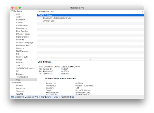
Why ? I don't know. I made some resarch in the Student's Archive and ask for advice to my instructor and fellow student but the only answer I got were (maybe a cold joint, try changing a resistor)... that is to say ... I may or may not solder another ISP.
Success with Hello board and ArduinoISP
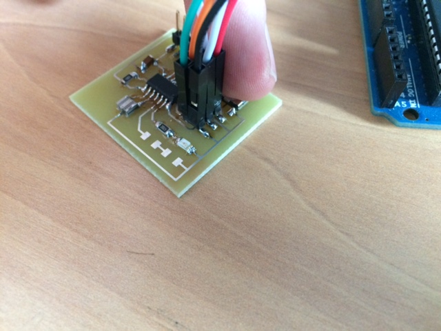
Since my ArduinoISP works I decided to fulfill the assignment to program the HelloBoard. I connected the SPI pins plus VCC (5V) and GND of the Arduino to the ICSP header of the HelloBoard.

I used the following code to control the LED with the button on my HelloBoard.
const int buttonPin = 3;     // the number of the pushbutton pin
const int ledPin = 7;      // the number of the LED pin


int buttonState = 0;         // variable for reading the pushbutton status

void setup() {
  // initialize the LED pin as an output:
  pinMode(ledPin, OUTPUT);
  // initialize the pushbutton pin as an input:
  pinMode(buttonPin, INPUT);
}

void loop() {
  // read the state of the pushbutton value:
  buttonState = digitalRead(buttonPin);

  // check if the pushbutton is pressed.
  // if it is, the buttonState is HIGH:
  if (buttonState == LOW) {
    // turn LED on:
    for (int fadeValue = 0 ; fadeValue <= 255; fadeValue += 5) {
    // sets the value (range from 0 to 255):
    analogWrite(ledPin, fadeValue);
    // wait for 30 milliseconds to see the dimming effect
    delay(1);
    }
  }
  else {
    // turn LED off:
    digitalWrite(ledPin, LOW);
  }
}
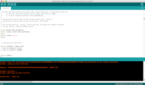
I used the following configuration in the Arduino IDE for the HelloBoard:
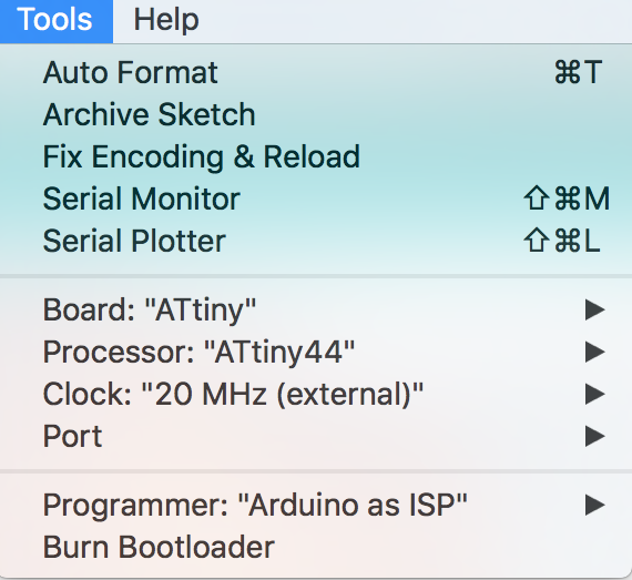
and uploaded the code with the Ardunino IDE. In verbose mode, avrdude gave:
avrdude: Version 6.0.1, compiled on Apr 14 2015 at 16:30:25
         Copyright (c) 2000-2005 Brian Dean, http://www.bdmicro.com/
         Copyright (c) 2007-2009 Joerg Wunsch

         System wide configuration file is "/Applications/Arduino.app/Contents/Java/hardware/tools/avr/etc/avrdude.conf"
         User configuration file is "/Users/vjmdupuis/.avrduderc"
         User configuration file does not exist or is not a regular file, skipping

         Using Port                    : /dev/cu.usbmodem1421
         Using Programmer              : stk500v1
         Overriding Baud Rate          : 19200
         AVR Part                      : ATtiny44
         Chip Erase delay              : 4500 us
         PAGEL                         : P00
         BS2                           : P00
         RESET disposition             : possible i/o
         RETRY pulse                   : SCK
         serial program mode           : yes
         parallel program mode         : yes
         Timeout                       : 200
         StabDelay                     : 100
         CmdexeDelay                   : 25
         SyncLoops                     : 32
         ByteDelay                     : 0
         PollIndex                     : 3
         PollValue                     : 0x53
         Memory Detail                 :

                                  Block Poll               Page                       Polled
           Memory Type Mode Delay Size  Indx Paged  Size   Size #Pages MinW  MaxW   ReadBack
           ----------- ---- ----- ----- ---- ------ ------ ---- ------ ----- ----- ---------
           eeprom        65     6     4    0 no        256    4      0  4000  4500 0xff 0xff
           flash         65     6    32    0 yes      4096   64     64  4500  4500 0xff 0xff
           signature      0     0     0    0 no          3    0      0     0     0 0x00 0x00
           lock           0     0     0    0 no          1    0      0  9000  9000 0x00 0x00
           lfuse          0     0     0    0 no          1    0      0  9000  9000 0x00 0x00
           hfuse          0     0     0    0 no          1    0      0  9000  9000 0x00 0x00
           efuse          0     0     0    0 no          1    0      0  9000  9000 0x00 0x00
           calibration    0     0     0    0 no          1    0      0     0     0 0x00 0x00

         Programmer Type : STK500
         Description     : Atmel STK500 Version 1.x firmware
         Hardware Version: 2
         Firmware Version: 1.18
         Topcard         : Unknown
         Vtarget         : 0.0 V
         Varef           : 0.0 V
         Oscillator      : Off
         SCK period      : 0.1 us

avrdude: AVR device initialized and ready to accept instructions

Reading | ################################################## | 100% 0.02s

avrdude: Device signature = 0x1e9207
avrdude: NOTE: "flash" memory has been specified, an erase cycle will be performed
         To disable this feature, specify the -D option.
avrdude: erasing chip
avrdude: reading input file "/var/folders/7x/hxjnyz8j0sd57wwvv0rf004h0000gn/T/build974d0bebc004a74520584d21c293df8d.tmp/PushLed.ino.hex"
avrdude: writing flash (1314 bytes):

Writing | ################################################## | 100% 1.90s

avrdude: 1314 bytes of flash written
avrdude: verifying flash memory against /var/folders/7x/hxjnyz8j0sd57wwvv0rf004h0000gn/T/build974d0bebc004a74520584d21c293df8d.tmp/PushLed.ino.hex:
avrdude: load data flash data from input file /var/folders/7x/hxjnyz8j0sd57wwvv0rf004h0000gn/T/build974d0bebc004a74520584d21c293df8d.tmp/PushLed.ino.hex:
avrdude: input file /var/folders/7x/hxjnyz8j0sd57wwvv0rf004h0000gn/T/build974d0bebc004a74520584d21c293df8d.tmp/PushLed.ino.hex contains 1314 bytes
avrdude: reading on-chip flash data:

Reading | ################################################## | 100% 0.95s

avrdude: verifying ...
avrdude: 1314 bytes of flash verified

avrdude done.  Thank you.
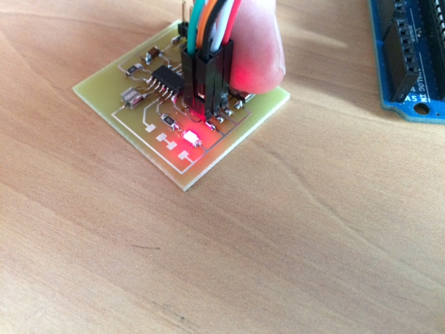
Firmware upload succeeded and finally I could command the LED with the button.