Project Development
Assignment for this week
- complete your final project, tracking your progress:
- what tasks have been completed, and what tasks remain?
- what has worked? what hasn't?
- what questions need to be resolved?
- what will happen when?
- what have you learned?
- documentation during development
- demand- vs supply-side time management
- spiral development
- Link to this week’s homeworkpage
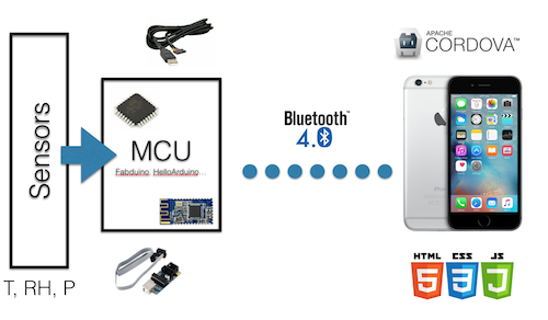
I describe here the different setps in the development of my fabacademy final project which consists in making a weather station connected to a smartphone through bluetooth low energy.
- The Sensors
- Bluetooth Low Energy (BLE)
- The fabduino and the HelloArduino boards
- Creating a smartphone app
- Designing and making a case
- Powering the weather station
- Finalizing the app
- Final test
- Update after final project presentation
- Update after 1st evaluation round
The sensors
Temperature/Relative Humidity and Barometer
For my weather station I needed at least three sensors: a temperature sensor, a humidity sensor and a pressure sensor. I already had a couple two grove sensors distributed by Seeedstudio: a digital temperature and relative humidity sensor based on a DHT22/AM2302, and a I2C barometer (high accuracy) based on a HP206C.
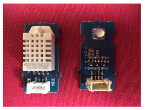
To test the sensors I decided to experiment with an arduino uno and used the sketches found on the Seeedstudio wiki pages. The grove version of the DHT22 has 3 pins: VCC, GND that should be connected to corresponding pins on the arduino and SIG that must be connected to a digital input pin. A DHT library in the form of a DHT.h and a DHT.cpp is provided.
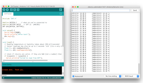
The code used is the following:
#include "DHT.h"

#define DHTPIN 2     // what pin we're connected to
#define DHTTYPE DHT22   // DHT 22  (AM2302)
DHT dht(DHTPIN, DHTTYPE);

void setup() {
  Serial.begin(9600);
  Serial.println("DHTxx test!");
  dht.begin();
}

void loop() {
  // Reading temperature or humidity takes about 250 milliseconds!
  // Sensor readings may also be up to 2 seconds 'old' (its a very slow sensor)
  float h = dht.readHumidity();
  float t = dht.readTemperature();

  // check if returns are valid, if they are NaN (not a number) then something went wrong!
  if (isnan(t) || isnan(h)) {
    Serial.println("Failed to read from DHT");
  } else {
    Serial.print("Humidity: ");
    Serial.print(h);
    Serial.print(" %\t");
    Serial.print("Temperature: ");
    Serial.print(t);
    Serial.println(" *C");
  }
}
I tested in the same way the I2C barometer. In order to use I2C/TWI interface with the arduino it is necessary to include the Wire library. The barometer sensor has four pins: VCC/GND and the two SDA and SCL that should be connected to A4 and A5 on the arduino uno respectively.
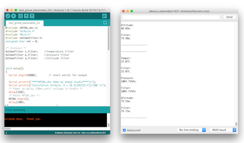
The code used is the following:
#include <HP20x_dev.h>
#include "Arduino.h"
#include "Wire.h"
#include <KalmanFilter.h>
unsigned char ret = 0;

/* Instance */
KalmanFilter t_filter;    //temperature filter
KalmanFilter p_filter;    //pressure filter
KalmanFilter a_filter;    //altitude filter


void setup()
{
  Serial.begin(9600);        // start serial for output

  Serial.println("****HP20x_dev demo by seeed studio****\n");
  Serial.println("Calculation formula: H = [8.5(101325-P)]/100 \n");
  /* Power up,delay 150ms,until voltage is stable */
  delay(150);
  /* Reset HP20x_dev */
  HP20x.begin();
  delay(100);

  /* Determine HP20x_dev is available or not */
  ret = HP20x.isAvailable();
  if(OK_HP20X_DEV == ret)
  {
    Serial.println("HP20x_dev is available.\n");
  }
  else
  {
    Serial.println("HP20x_dev isn't available.\n");
  }

}


void loop()
{
    char display[40];
    if(OK_HP20X_DEV == ret)
    {
    Serial.println("------------------\n");
    long Temper = HP20x.ReadTemperature();
    Serial.println("Temper:");
    float t = Temper/100.0;
    Serial.print(t);
    Serial.println("C.\n");
    Serial.println("Filter:");
    Serial.print(t_filter.Filter(t));
    Serial.println("C.\n");

      long Pressure = HP20x.ReadPressure();
    Serial.println("Pressure:");
    t = Pressure/100.0;
    Serial.print(t);
    Serial.println("hPa.\n");
    Serial.println("Filter:");
    Serial.print(p_filter.Filter(t));
    Serial.println("hPa\n");

    long Altitude = HP20x.ReadAltitude();
    Serial.println("Altitude:");
    t = Altitude/100.0;
    Serial.print(t);
    Serial.println("m.\n");
    Serial.println("Filter:");
    Serial.print(a_filter.Filter(t));
    Serial.println("m.\n");
    Serial.println("------------------\n");
      delay(1000);
    }
}
All in one Temperature/Relative Humidity/Barometer
I also baught a three in one adafruit temperature, humidity, pressure SPI sensor based on a BOSCH BMP280 digital pressure sensor.
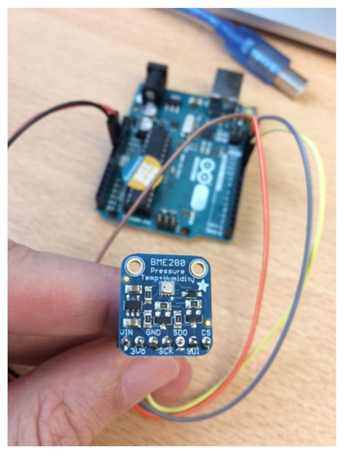
As for the previous sensors, I tested the sensor following indications given here.. The Serial Peripheral Interface (SPI) wiring of the sensor pins to the uno is the following:
- Vin connected to 5V
- GND connected to GND
- SCK (serial clock) connected to pin D13
- SDO (also called MISO for Master In Slave Out) connected to D12
- SDI (also called MOSI for Master Out Slave In) connected to D11
- CS (also called SS for Slave Select) connected to D10
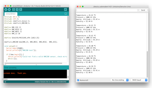
The code used is the following:
#include <Wire.h>
#include <SPI.h>
#include <Adafruit_Sensor.h>
#include <Adafruit_BME280.h>

#define BME_SCK 13
#define BME_MISO 12
#define BME_MOSI 11
#define BME_CS 10

#define SEALEVELPRESSURE_HPA (1013.25)

Adafruit_BME280 bme(BME_CS, BME_MOSI, BME_MISO,  BME_SCK);

void setup() {
  Serial.begin(9600);
  Serial.println(F("BME280 test"));

  if (!bme.begin()) {
    Serial.println("Could not find a valid BME280 sensor, check wiring!");
    while (1);
  }
}

void loop() {
    Serial.print("Temperature = ");
    Serial.print(bme.readTemperature());
    Serial.println(" *C");

    Serial.print("Pressure = ");

    Serial.print(bme.readPressure() / 100.0F);
    Serial.println(" hPa");

    Serial.print("Approx. Altitude = ");
    Serial.print(bme.readAltitude(SEALEVELPRESSURE_HPA));
    Serial.println(" m");

    Serial.print("Humidity = ");
    Serial.print(bme.readHumidity());
    Serial.println(" %");

    Serial.println();
    delay(2000);
}
Summary
Besides VCC and GND, the use of the two separate Temperature/Humidity and Temperature/Barometer sensors requires 1 (D2)+2 (A4-A5) = 3 pins on the ATMega328P while the use of the all in one SPI sensor will 4 pins (MISO/MOSI, SCK, SS). Both solutions should be ok with the Fabduino or even the HelloArduino boards.
Bluetooth Low Energy (BLE)
The choice of BLE to transfer the data from the board to the smartphone instead of wifi was done with the idea of using wifi to connect to a distant server to tranfer the sensors data combined with the geolocation of the smartphone for instance even if that part is out of the scope of the present project.
The HM10 module - experimenting with an Arduino Uno
The HM10 BLE module presented in class. Additional documentations can be found here. In order to avoid taking care of the 3.3V requirement I baught a breakout module that integrate a regulator and headers. The module has 6 pins (STATE, VCC, GND, TXD, RXD, BRK). I only used 4 and connected:
- VCC to 5V
- GND to GND
- TXD to pin D10
- RXD to pin D11
on the arduino and used SoftwareSerial to avoid interference with RX/TX used by the Arduino IDE when uploading sketches.

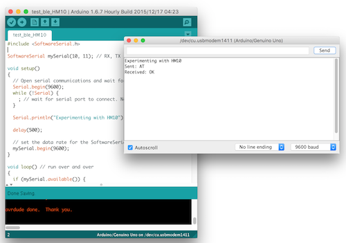
I used a basic send/receive code to talk to the HM10:
#include <SoftwareSerial.h>

SoftwareSerial mySerial(10, 11); // RX, TX

void setup()
{
  // Open serial communications and wait for port to open:
  Serial.begin(9600);
  while (!Serial) {
    ; // wait for serial port to connect. Needed for Leonardo only
  }

  Serial.println("Experimenting with HM10");

  delay(500);

  // set the data rate for the SoftwareSerial port
  mySerial.begin(9600);
}

void loop() // run over and over
{
  if (mySerial.available()) {
    String s = "";
    char c;
    while((c = mySerial.read()) != -1) {
      s += c;
      delay(10);
    }

    Serial.println("Received: " + s);
  }

  if (Serial.available()) {
    String s = "";
    char c;
    while((c = Serial.read()) != -1) {
      s += c;
      delay(10);
    }

    delay(10);

    Serial.println("Sent: " + s);

    mySerial.print(s);
  }
}
Uploading the sketch to the arduino allowed me to send AT commands and received answers from the HM10. I could have done the same with the FTDI cable using direct serial communication (and I did). Note that communication can be a bit tricky. I actually used several HM10. Some require no line ending, some require carriage return (CR) and new line (NL). Some require the question mark ? to get answer, some don't. All this is to my opinion quite poorly documented and quite confusing on the web and this made me loose a lot of time.
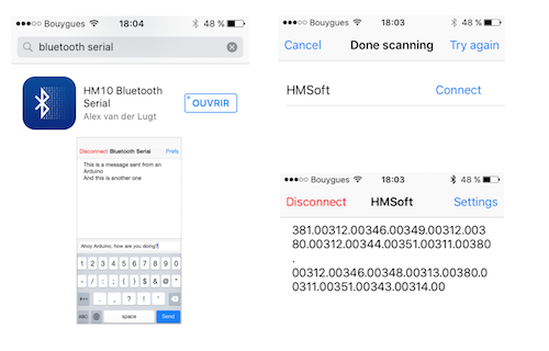
Based on this success, I could modify the arduino sketch to send data (value = analogRead(0); then mySerial.println(value);) over BLE and read with a BLE scanning app such as HM10 Bluetooth Serial.
Making the fabduino and the HelloArduino boards
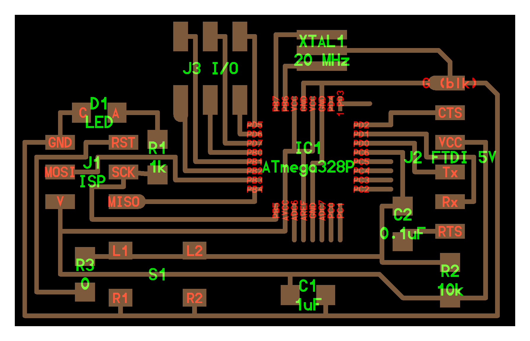
Fabduino
The fabduino is a fabacademy clone of the arduino uno board that uses an ATMega328P microcontroller. Everything that runs on an arduino uno should run on the fabduino.
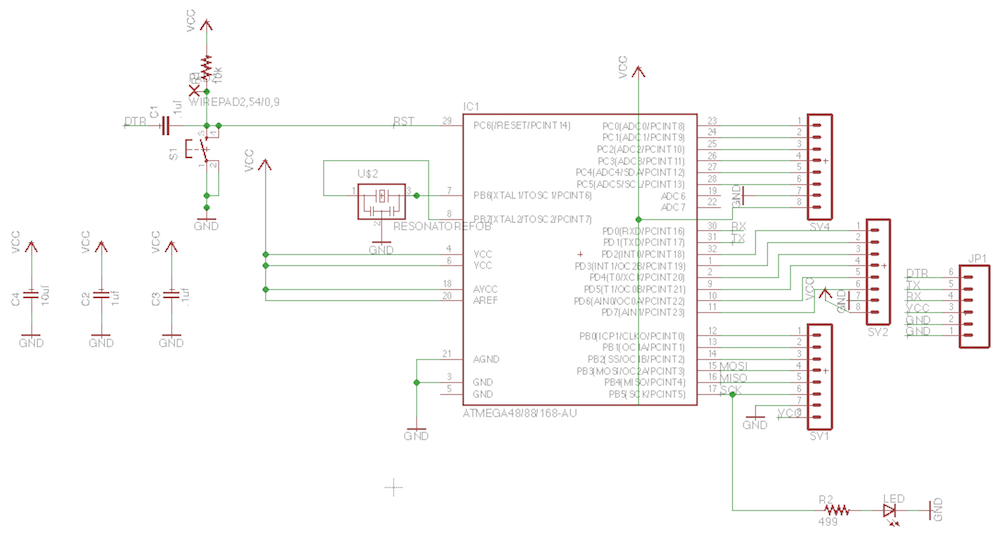
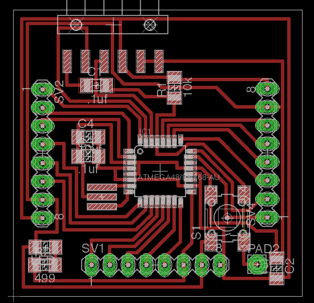
The mapping of the pins of the arduino uno to the pins of the fabduino is the following:

ISP programming can be done using the "SPI" pinout:
- Vin connected to 5V
- GND connected to GND
- SCK connected to pin D13
- MISO connected to D12
- MOSI connected to D11
- SS connected to D10
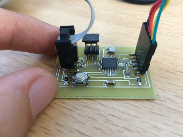
I etched the board, soldered the components and made a ribbon cable with ISP connector at one end and separated female jumpers on the other end to easily connect to pin D10-13 and GND/VCC.
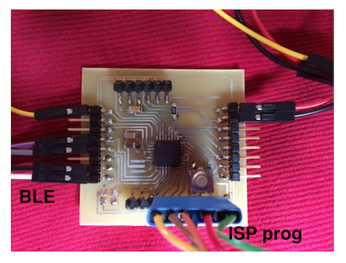
To program my fabduino, I used my USBTiny programmer and following config in the Arduino IDE:
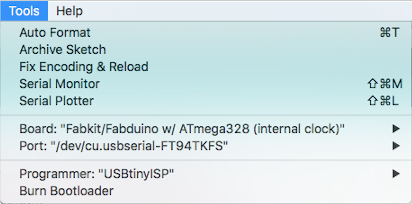
I could upload a basic sketch (IMPORTANT: after burning the bootloader) that reads analog pin 0 and serial print it. The log and the screenshot are given below:
[...]
Sketch uses 2,354 bytes (16%) of program storage space. Maximum is 14,336 bytes.
Global variables use 200 bytes of dynamic memory.
/Applications/Arduino.app/Contents/Java/hardware/tools/avr/bin/avrdude -C/Applications/Arduino.app/Contents/Java/hardware/tools/avr/etc/avrdude.conf -v -patmega328p -cusbtiny -Uflash:w:/var/folders/7x/hxjnyz8j0sd57wwvv0rf004h0000gn/T/build9782b027e0709dc7679687f19489dfc9.tmp/test_fabduino.ino.hex:i

avrdude: Version 6.0.1, compiled on Apr 14 2015 at 16:30:25
         Copyright (c) 2000-2005 Brian Dean, http://www.bdmicro.com/
         Copyright (c) 2007-2009 Joerg Wunsch

         System wide configuration file is "/Applications/Arduino.app/Contents/Java/hardware/tools/avr/etc/avrdude.conf"
         User configuration file is "/Users/vjmdupuis/.avrduderc"
         User configuration file does not exist or is not a regular file, skipping

         Using Port                    : usb
         Using Programmer              : usbtiny
avrdude: usbdev_open(): Found USBtinyISP, bus:device: 020:008
         AVR Part                      : ATmega328P
         Chip Erase delay              : 9000 us
         PAGEL                         : PD7
         BS2                           : PC2
         RESET disposition             : dedicated
         RETRY pulse                   : SCK
         serial program mode           : yes
         parallel program mode         : yes
         Timeout                       : 200
         StabDelay                     : 100
         CmdexeDelay                   : 25
         SyncLoops                     : 32
         ByteDelay                     : 0
         PollIndex                     : 3
         PollValue                     : 0x53
         Memory Detail                 :

                                  Block Poll               Page                       Polled
           Memory Type Mode Delay Size  Indx Paged  Size   Size #Pages MinW  MaxW   ReadBack
           ----------- ---- ----- ----- ---- ------ ------ ---- ------ ----- ----- ---------
           eeprom        65    20     4    0 no       1024    4      0  3600  3600 0xff 0xff
           flash         65     6   128    0 yes     32768  128    256  4500  4500 0xff 0xff
           lfuse          0     0     0    0 no          1    0      0  4500  4500 0x00 0x00
           hfuse          0     0     0    0 no          1    0      0  4500  4500 0x00 0x00
           efuse          0     0     0    0 no          1    0      0  4500  4500 0x00 0x00
           lock           0     0     0    0 no          1    0      0  4500  4500 0x00 0x00
           calibration    0     0     0    0 no          1    0      0     0     0 0x00 0x00
           signature      0     0     0    0 no          3    0      0     0     0 0x00 0x00

         Programmer Type : USBtiny
         Description     : USBtiny simple USB programmer, http://www.ladyada.net/make/usbtinyisp/
avrdude: programmer operation not supported

avrdude: Using SCK period of 10 usec
avrdude: AVR device initialized and ready to accept instructions

Reading | ################################################## | 100% 0.01s

avrdude: Device signature = 0x1e950f
avrdude: NOTE: "flash" memory has been specified, an erase cycle will be performed
         To disable this feature, specify the -D option.
avrdude: erasing chip
avrdude: Using SCK period of 10 usec
avrdude: reading input file "/var/folders/7x/hxjnyz8j0sd57wwvv0rf004h0000gn/T/build9782b027e0709dc7679687f19489dfc9.tmp/test_fabduino.ino.hex"
avrdude: writing flash (2354 bytes):

Writing | #####avrdude: stk500_getsync() attempt 1 of 10: not in sync: resp=0x30
avrdude: stk500_getsync() attempt 2 of 10: not in sync: resp=0x20
avrdude: stk500_getsync() attempt 3 of 10: not in sync: resp=0x30
##avrdude: stk500_getsync() attempt 4 of 10: not in sync: resp=0x20
avrdude: stk500_getsync() attempt 5 of 10: not in sync: resp=0x30
avrdude: stk500_getsync() attempt 6 of 10: not in sync: resp=0x20
avrdude: stk500_getsync() attempt 7 of 10: not in sync: resp=0x30
avrdude: stk500_getsync() attempt 8 of 10: not in sync: resp=0x20
avrdude: stk500_getsync() attempt 9 of 10: not in sync: resp=0x30
avrdude: stk500_getsync() attempt 10 of 10: not in sync: resp=0x20
###
avrdude done.  Thank you.

######################################## | 100% 3.78s

avrdude: 2354 bytes of flash written
avrdude: verifying flash memory against /var/folders/7x/hxjnyz8j0sd57wwvv0rf004h0000gn/T/build9782b027e0709dc7679687f19489dfc9.tmp/test_fabduino.ino.hex:
avrdude: load data flash data from input file /var/folders/7x/hxjnyz8j0sd57wwvv0rf004h0000gn/T/build9782b027e0709dc7679687f19489dfc9.tmp/test_fabduino.ino.hex:
avrdude: input file /var/folders/7x/hxjnyz8j0sd57wwvv0rf004h0000gn/T/build9782b027e0709dc7679687f19489dfc9.tmp/test_fabduino.ino.hex contains 2354 bytes
avrdude: reading on-chip flash data:

Reading | ################################################## | 100% 2.14s

avrdude: verifying ...
avrdude: 2354 bytes of flash verified

avrdude done.  Thank you.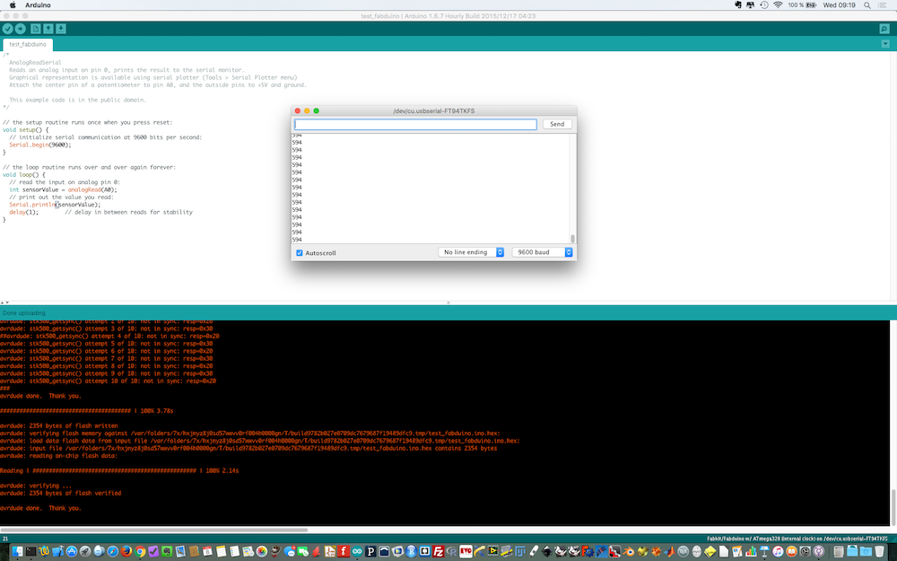
HelloArduino
In the board section of the Embedded programming class, another arduino-like board name hello.arduino.328P was introduced.
I gives access to less pins than the fabduino (6 in total PB0, PB1, PB2 and PD5, PD6, PD7). Additionnal pins can be used onced programmed (4 pins on the ISP header plus GND/VCC and the two pins RX/TX plus GND/VCC on the FTDI header). This should be ok for my sensors since I need 4 pins + 2 for bluetooth. I etched a hello.arduino.328P board and soldered the components.
Creating a smartphone app.
Installing Cordova/Phonegap
As I wanted to create a smartphone app that could run both under Android and iOs I decided to use the Cordova/Phonegap framework and program the app using HTML/CSS/javascript. Creating an app under Cordova consist in creating the User Interface using HTML/CSS and the code that will handles the different events using javascript. Cordova command-line requires Node.js and can be installed using NPM (the node package manager). Documentation can be found here.
$ npm install -g cordovaCreating an app
Creating an app begins with creating a cordova project in a given folder. At this step, the documentation can be useful.
$ cordova create <app-folder> <app-identifier> <app-name>Cordova then creates a basic app with the following directory structure:
myapp/
|-- config.xml
|-- hooks/
|-- www/
  |--css/
    |--index.css
  |--js/
    |--index.js
  |--index.html
|-- platforms/
|-- plugins/
The app consists of three files in the www folder: index.html, index.css and index.js. To build the app for a given OS,
$ cordova platform add <platform-name>
$ cordova build <platform-name>
For instance, for an iphone app running under iOS
$ cordova platform add ios
$ cordova build ios
Cordova then creates a ios/ folder in the platforms/folder with different subfolders and a .xcodeproj file (actually a folder) that can be opened in Xcode and uploaded to the iphone (provided you have a valid Apple developer license).
In order to use the hardware features of the smartphone it is necessary to include plugins that will sit in the plugins/ folder
$ cordova plugin add <plugin-name>BLE plugin and HM10 module
In order to use HM10 Bluetooth Low Energy module, it is necessary to include a BLE cordova plugin. I used the Bluetooth Low Energy (BLE) Central Plugin for Apache Cordova provided by Don on github. Of course, this was not straitforward and I had to spend some time researching on the web before achieving some success with Cordova and the BLE plugin.
$ cordova plugin add cordova-plugin-ble-centralThe HM10 module is base on Texas Instrument CC2541 MCU. Following discussions, I started with the BluefruitLE example app initially designed for the Bluefruit LE - Bluetooth Low Energy (BLE 4.0) - nRF8001 which uses a Nordic nRF8001 chip instead of a TI CC2451. I had to identify the right UUIDs to match BLE services on the HM10 and change
// this is Nordic's UART service
var bluefruit = {
    serviceUUID: '0000ffe0-0000-1000-8000-00805f9b34fb',
    txCharacteristic: '0000ffe1-0000-1000-8000-00805f9b34fb', // transmit is from the phone's perspective
    rxCharacteristic: '0000ffe1-0000-1000-8000-00805f9b34fb'  // receive is from the phone's perspective
};
to
// TI CC2451 (HM10) UART service
var bluefruit = {
    serviceUUID: 'ffe0',
    txCharacteristic: 'ffe1', // transmit is from the phone's perspective
    rxCharacteristic: 'ffe1'  // receive is from the phone's perspective
};
in the main index.js javascript code. With this changes I could build the BluefruitLE app example on my iphone and establish a serial communication using BLE with the HM10 module and test the response to AT commands. The full index.jscode:
// (c) 2014 Don Coleman
//
// Licensed under the Apache License, Version 2.0 (the "License");
// you may not use this file except in compliance with the License.
// You may obtain a copy of the License at
//
//     http://www.apache.org/licenses/LICENSE-2.0
//
// Unless required by applicable law or agreed to in writing, software
// distributed under the License is distributed on an "AS IS" BASIS,
// WITHOUT WARRANTIES OR CONDITIONS OF ANY KIND, either express or implied.
// See the License for the specific language governing permissions and
// limitations under the License.

/* global mainPage, deviceList, refreshButton */
/* global detailPage, resultDiv, messageInput, sendButton, disconnectButton */
/* global ble  */
/* jshint browser: true , devel: true*/
'use strict';

// ASCII only
function bytesToString(buffer) {
    return String.fromCharCode.apply(null, new Uint8Array(buffer));
}

// ASCII only
function stringToBytes(string) {
    var array = new Uint8Array(string.length);
    for (var i = 0, l = string.length; i < l; i++) {
        array[i] = string.charCodeAt(i);
    }
    return array.buffer;
}

// this is Nordic's UART service
//var bluefruit = {
//    serviceUUID: '0000ffe0-0000-1000-8000-00805f9b34fb',
//    txCharacteristic: '0000ffe1-0000-1000-8000-00805f9b34fb', // transmit is from the phone's perspective
//    rxCharacteristic: '0000ffe1-0000-1000-8000-00805f9b34fb'  // receive is from the phone's perspective
//};
// TI CC2451 (HM10) UART service
var bluefruit = {
    serviceUUID: 'ffe0',
    txCharacteristic: 'ffe1', // transmit is from the phone's perspective
    rxCharacteristic: 'ffe1'  // receive is from the phone's perspective
};

var app = {
    initialize: function() {
        this.bindEvents();
        detailPage.hidden = true;
    },
    bindEvents: function() {
        document.addEventListener('deviceready', this.onDeviceReady, false);
        refreshButton.addEventListener('touchstart', this.refreshDeviceList, false);
        sendButton.addEventListener('click', this.sendData, false);
        disconnectButton.addEventListener('touchstart', this.disconnect, false);
        deviceList.addEventListener('touchstart', this.connect, false); // assume not scrolling
    },
    onDeviceReady: function() {
        app.refreshDeviceList();
    },
    refreshDeviceList: function() {
        deviceList.innerHTML = ''; // empties the list
        if (cordova.platformId === 'android') { // Android filtering is broken
            ble.scan([], 5, app.onDiscoverDevice, app.onError);
        } else {
            ble.scan([bluefruit.serviceUUID], 5, app.onDiscoverDevice, app.onError);
        }
    },
    onDiscoverDevice: function(device) {
        var listItem = document.createElement('li'),
            html = '' + device.name + '
' +
                'RSSI: ' + device.rssi + ' | ' +
                device.id;

        listItem.dataset.deviceId = device.id;
        listItem.innerHTML = html;
        deviceList.appendChild(listItem);
    },
    connect: function(e) {
        var deviceId = e.target.dataset.deviceId,
            onConnect = function(peripheral) {
                app.determineWriteType(peripheral);

                // subscribe for incoming data
                ble.startNotification(deviceId, bluefruit.serviceUUID, bluefruit.rxCharacteristic, app.onData, app.onError);
                sendButton.dataset.deviceId = deviceId;
                disconnectButton.dataset.deviceId = deviceId;
                resultDiv.innerHTML = "";
                app.showDetailPage();

            };

        ble.connect(deviceId, onConnect, app.onError);
    },
    determineWriteType: function(peripheral) {
        // Adafruit nRF8001 breakout uses WriteWithoutResponse for the TX characteristic
        // Newer Bluefruit devices use Write Request for the TX characteristic

        var characteristic = peripheral.characteristics.filter(function(element) {
            if (element.characteristic.toLowerCase() === bluefruit.txCharacteristic) {
                return element;
            }
        })[0];

        if (characteristic.properties.indexOf('WriteWithoutResponse') > -1) {
            app.writeWithoutResponse = true;
        } else {
            app.writeWithoutResponse = false;
        }

    },
    onData: function(data) { // data received from Arduino
        console.log(data);
        resultDiv.innerHTML = resultDiv.innerHTML + "Received: " + bytesToString(data) + "
";
        resultDiv.scrollTop = resultDiv.scrollHeight;
    },
    sendData: function(event) { // send data to Arduino

        var success = function() {
            console.log("success");
            resultDiv.innerHTML = resultDiv.innerHTML + "Sent: " + messageInput.value + "
";
            resultDiv.scrollTop = resultDiv.scrollHeight;
        };

        var failure = function() {
            alert("Failed writing data to the bluefruit le");
        };

        var data = stringToBytes(messageInput.value);
        var deviceId = event.target.dataset.deviceId;

        if (app.writeWithoutResponse) {
            ble.writeWithoutResponse(
                deviceId,
                bluefruit.serviceUUID,
                bluefruit.txCharacteristic,
                data, success, failure
            );
        } else {
            ble.write(
                deviceId,
                bluefruit.serviceUUID,
                bluefruit.txCharacteristic,
                data, success, failure
            );
        }

    },
    disconnect: function(event) {
        var deviceId = event.target.dataset.deviceId;
        ble.disconnect(deviceId, app.showMainPage, app.onError);
    },
    showMainPage: function() {
        mainPage.hidden = false;
        detailPage.hidden = true;
    },
    showDetailPage: function() {
        mainPage.hidden = true;
        detailPage.hidden = false;
    },
    onError: function(reason) {
        alert("ERROR: " + reason); // real apps should use notification.alert
    }
};
Designing and making a case
In order to obtain a working and transportable prototype, it was necessary to design a case. I used openSCAD and Inkscape.
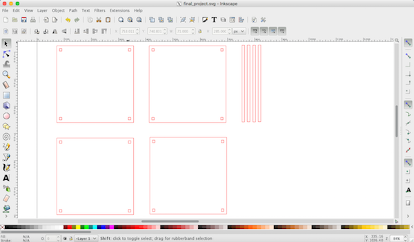
I used 3 mm thick acrylic and our laser cutter to prepare the case.

Then I drilled holes and shaped M2 threads in order to screw the sensors.
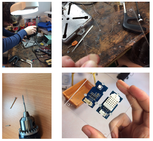
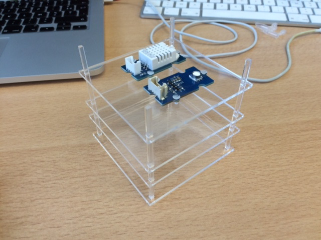
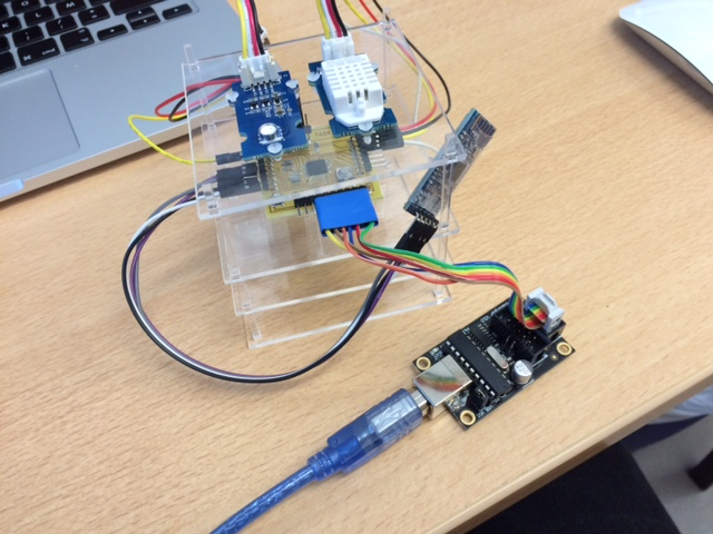
Assembling the parts gave me this:
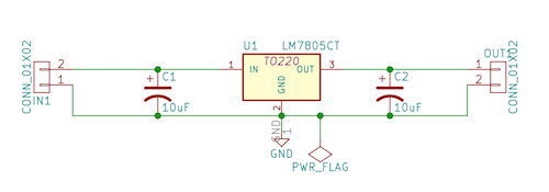
Powering the weather station
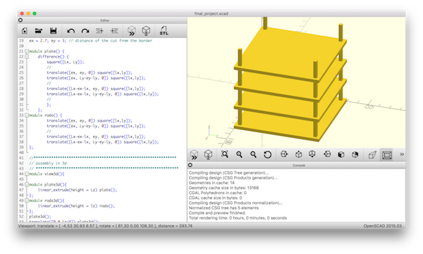
During all the preliminary tests, the fabduino was powered by the the ISP programmer or the FTDI cable. In order to have an autonomous device I needed a battery to deliver the 5V required by the board and sensors. I chose to use 4 AAA 1.5V batteries. With 4 batteries I could generate 6V, I thus needed a regulator to deliver exactly 5V from the 6V delivered by the 4 AAA batteries. I decided to design a board based on a LM7805 regulator. I used KiCAD. Here is the schematic:
the board layout
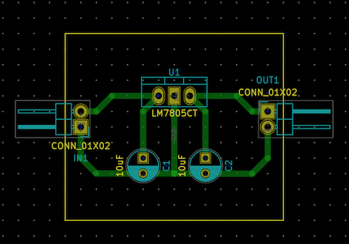
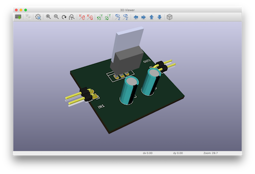
and a 3d view
I etched the board and soldered the components.
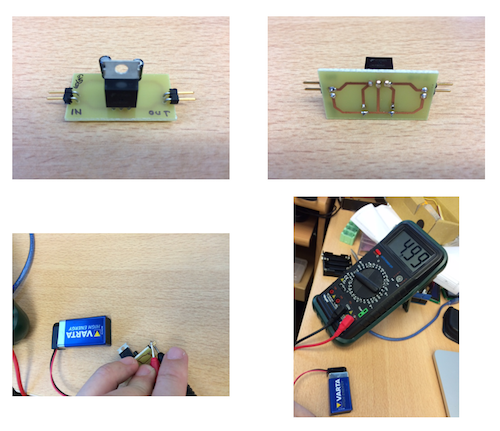
I checked with a 9V battery that the voltage at the ouput of the regulator board was indeed 5V.
Finalizing the app and the firmware
Beyond being able to use the BLE plugin and a modified version of the BluefruitLE app I wanted to create my own app with icons for the temperature, humidity and pressure. I downloaded 3 nice icons from Openclipart and decided to create with the following design:
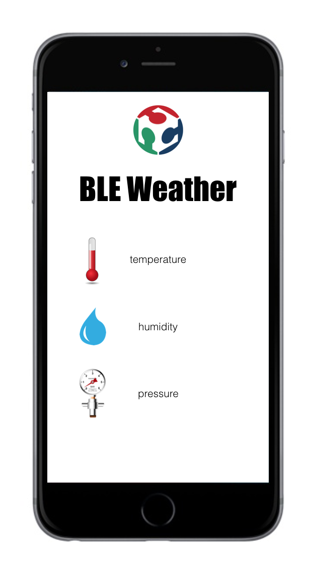
I decided to use jQuery to manipulate forms objects, appearance/disappearance, etc... and to embed icons and text in a <div> equivalent of an HTML table. I also modified the firmware to send data in the form of 4 bytes float number instead of ASCII char chain since the HM10 has a limited number of 20 data bytes. I adapted to the app to deal with this format. The final firmware is:
#include <SoftwareSerial.h>

SoftwareSerial mySerial(5, 6); // RX, TX

float sensorValue[3] = {0,0,0};

#include "DHT.h"
#include "Wire.h"
#include
#include "Arduino.h"
#include

#define DHTPIN 2     // what pin we're connected to
#define DHTTYPE DHT22   // DHT 22  (AM2302)
DHT dht(DHTPIN, DHTTYPE);

unsigned char ret = 0;

/* Instance */
KalmanFilter t_filter;    //temperature filter
KalmanFilter p_filter;    //pressure filter
KalmanFilter a_filter;    //altitude filter


void setup() {
  //Serial.begin(9600);
  //Serial.println("DHT22 initialization!");
  dht.begin();
  //Serial.println("Barometer initialization!");
  HP20x.begin();
  delay(100);
  //Serial.println("----------------------------");
  mySerial.begin(9600);

  /* Determine HP20x_dev is available or not */
  ret = HP20x.isAvailable();
  if(OK_HP20X_DEV == ret)
  {
    //Serial.println("HP20x_dev is available.\n");
  }
  else
  {
    //Serial.println("HP20x_dev isn't available.\n");
  }
}

void loop() {
  // Reading temperature or humidity takes about 250 milliseconds!
  // Sensor readings may also be up to 2 seconds 'old' (its a very slow sensor)
  float h = dht.readHumidity();
  float t1 = dht.readTemperature();

  // check if returns are valid, if they are NaN (not a number) then something went wrong!
  if (isnan(t1) || isnan(h)) {
    //Serial.println("Failed to read from DHT");
  } else {
    //Serial.print("T: ");
    //Serial.print(t1);
    //Serial.print(" H: ");
    //Serial.print(h);
    sensorValue[0] = t1;
    sensorValue[1] = h;
  }
  if(OK_HP20X_DEV == ret)
    {
    long Temper = HP20x.ReadTemperature();
    //Serial.print(" T: ");
    float t2 = Temper/100.0;
    //Serial.print(t2);
    long Pressure = HP20x.ReadPressure();
    //Serial.print(" P: ");
    float p = Pressure/100.0;
    //Serial.println(p);
    sensorValue[2] = p;
    }
    // main loop
    for(int k=0; k<3; k++)
    {
    //Serial.print(sensorValue[k]);
    //Serial.print(';');
    mySerialFloatPrint(sensorValue[k]);
    }
    //Serial.println();
    delay(2000);
}

void mySerialFloatPrint(float f) {
  byte * b = (byte *) &f;
  //mySerial.print("f:");
  mySerial.write(b[0]);
  mySerial.write(b[1]);
  mySerial.write(b[2]);
  mySerial.write(b[3]);
  /* DEBUG */
  //Serial.println();
  //Serial.print(b[0],BIN);
  //Serial.print(b[1], BIN);
  //Serial.print(b[2], BIN);
  //Serial.println(b[3], BIN);
  //*/
}
I could upload the firmware using my usbtiny ISP programmer and my homemade cable.
The javascript app is the following (all the files can be found on the summary page).
// (c) 2016 Vincent Dupuis adapted from Don Coleman
//
// Licensed under the Apache License, Version 2.0 (the "License");
// you may not use this file except in compliance with the License.
// You may obtain a copy of the License at
//
//     http://www.apache.org/licenses/LICENSE-2.0
//
// Unless required by applicable law or agreed to in writing, software
// distributed under the License is distributed on an "AS IS" BASIS,
// WITHOUT WARRANTIES OR CONDITIONS OF ANY KIND, either express or implied.
// See the License for the specific language governing permissions and
// limitations under the License.

/* global mainPage, deviceList, refreshButton */
/* global detailPage, resultDiv, messageInput, sendButton, disconnectButton */
/* global ble  */
/* jshint browser: true , devel: true*/
'use strict';

// array of 4 bytes data to array of floats
var arrayBufferToFloat = function (ab) {
    var a = new Float32Array(ab);
    return a;
};

// ASCII only
function bytesToString(buffer) {
    return String.fromCharCode.apply(null, new Uint8Array(buffer));
}

// ASCII only
function stringToBytes(string) {
    var array = new Uint8Array(string.length);
    for (var i = 0, l = string.length; i < l; i++) {
        array[i] = string.charCodeAt(i);
    }
    return array.buffer;
}

// this is Nordic's UART service
//var bluefruit = {
//    serviceUUID: '0000ffe0-0000-1000-8000-00805f9b34fb',
//    txCharacteristic: '0000ffe1-0000-1000-8000-00805f9b34fb', // transmit is from the phone's perspective
//    rxCharacteristic: '0000ffe1-0000-1000-8000-00805f9b34fb'  // receive is from the phone's perspective
//};
// TI CC2451 (HM10) UART service
var bluefruit = {
    serviceUUID: 'ffe0',
    txCharacteristic: 'ffe1', // transmit is from the phone's perspective
    rxCharacteristic: 'ffe1'  // receive is from the phone's perspective
};

var app = {
    initialize: function() {
        $('#detailPage').hide();
        this.bindEvents();
    },
    bindEvents: function() {
        document.addEventListener('deviceready', this.onDeviceReady, false);
        refreshButton.addEventListener('touchstart', this.refreshDeviceList, false);
        deviceList.addEventListener('touchstart', this.connect, false); // assume not scrolling
        disconnectButton.addEventListener('touchstart', this.disconnect, false);
    },
    onDeviceReady: function() {
        app.refreshDeviceList();
    },
    refreshDeviceList: function() {
        deviceList.innerHTML = ''; // empties the list
        if (cordova.platformId === 'android') { // Android filtering is broken
            ble.scan([], 5, app.onDiscoverDevice, app.onError);
        } else {
            ble.scan([bluefruit.serviceUUID], 5, app.onDiscoverDevice, app.onError);
        }
    },
    onDiscoverDevice: function(device) {
        var listItem = document.createElement('li'),
            html = '' + device.name + '
' +
                'RSSI: ' + device.rssi + ' | ' +
                device.id;

        listItem.dataset.deviceId = device.id;
        listItem.innerHTML = html;
        deviceList.appendChild(listItem);
    },
    connect: function(e) {
        var deviceId = e.target.dataset.deviceId,
            onConnect = function(peripheral) {
                app.determineWriteType(peripheral);

                $("#mainPage").hide();
                $("#detailPage").show();

                // subscribe for incoming data
                ble.startNotification(deviceId, bluefruit.serviceUUID, bluefruit.rxCharacteristic, app.onData, app.onError);
                disconnectButton.dataset.deviceId = deviceId;
                resultDiv.innerHTML = "";
                app.showDetailPage();
            };

        ble.connect(deviceId, onConnect, app.onError);
    },
    determineWriteType: function(peripheral) {
        // Adafruit nRF8001 breakout uses WriteWithoutResponse for the TX characteristic
        // Newer Bluefruit devices use Write Request for the TX characteristic

        var characteristic = peripheral.characteristics.filter(function(element) {
            if (element.characteristic.toLowerCase() === bluefruit.txCharacteristic) {
                return element;
            }
        })[0];

        if (characteristic.properties.indexOf('WriteWithoutResponse') > -1) {
            app.writeWithoutResponse = true;
        } else {
            app.writeWithoutResponse = false;
        }

    },
    onData: function(data) { // data received from Arduino
        console.log("onData");
        console.log(data);
        var dataArray = arrayBufferToFloat(data);

        //resultDiv.innerHTML = resultDiv.innerHTML + "R: " + bytesToString(data) + "
";
        //resultDiv.scrollTop = resultDiv.scrollHeight;

        var tempValue = dataArray[0];
        var humValue = dataArray[1];
        var pressureValue = dataArray[2];

        $("#temp").html(tempValue.toFixed(2));
        $("#hum").html(humValue.toFixed(2));
        $("#pressure").html(pressureValue.toFixed(2));
    },

    disconnect: function(event) {
        var deviceId = event.target.dataset.deviceId;
        ble.disconnect(deviceId, app.showMainPage, app.onError);
    },
    showMainPage: function() {
        $("#mainPage").show();
        $("#detailPage").hide();
    },
    showDetailPage: function() {
        $("#mainPage").hide();
        $("#detailPage").show();
    },
    onError: function(reason) {
        alert("ERROR: " + reason); // real apps should use notification.alert
    }
};
The main function is the onData line #120. It converts back the 4 bytes into floats and display the result in the field #temp, #hum and #pressure defined in the html file.
Final test
Adding the batteries, the regulator board, pluging everything I obtained:

Update after final project presentation
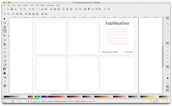
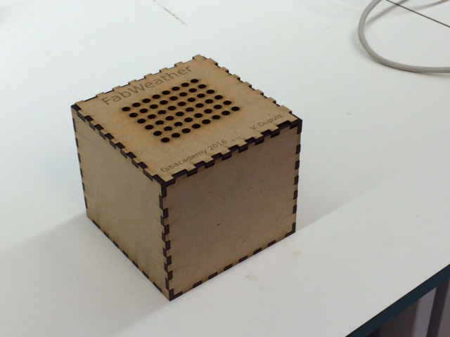
During final project presentation, Neil suggested to make a new casing. Indeed, I chose to make a completely open weather station so that anyone could see what's inside the box but the drawback is that cables are visbibles and the thing looks a bit messy. Following his suggestion I designed a new box in Inkscape:
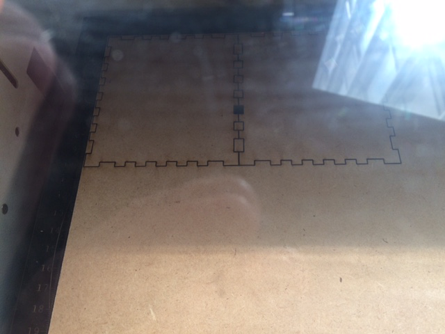
and lasercutted it:
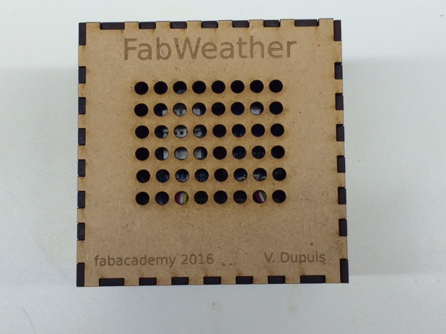
Finally after assembly and insertion of the weather station I obtained a cleaner object:
Update after 1st evaluation round
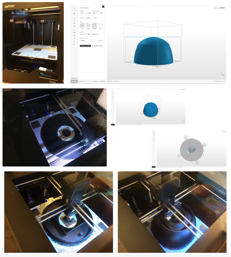
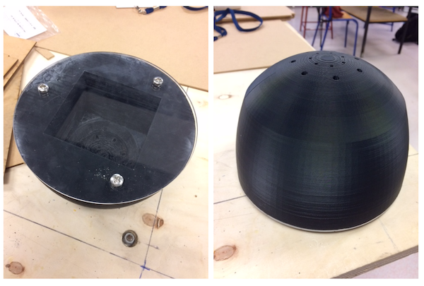
After 1st evaluation round, I was asked to include 3d printing in my final project. I decided to make a new box. I used Autodesk Fusion 360. It is basically a shell with a cubic hole inside to insert the weather station and holes on top for the sensors to give an accurate measure of temperature, humidity and pressure.
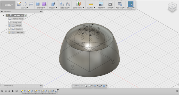
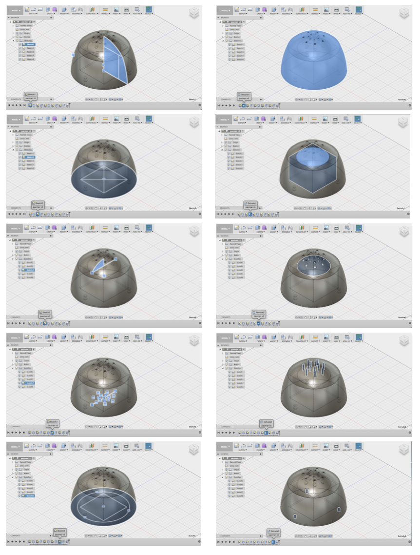
I first sketched the overall shape and used revolve to create a solid. I then sketched the square for the cubic hole and used extrude. I then sketched/revolved/extruded the hemispherical hole, the top holes and the bottom hole for screws.
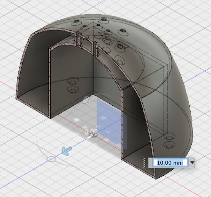
The shell is more visible using 'section' (in the inspect menu).
I used a Zortrax M200 to print the box. The part is big and it took more than 24h to print it. Due to temperature inhomonogenity on the plate, the raft tended to detach from the plate and it was necessary to add some additional filament (in white on the picture) with a 3d pencil to make the raft stick to the build plate.
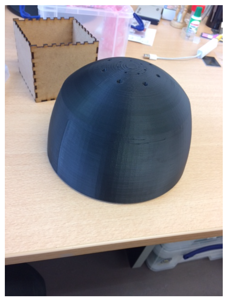
Finally, I swapped the lasercutted wooden box with the 3d printed one
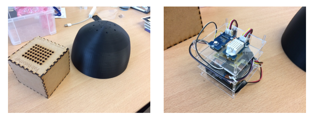
and obtained
I then designed a base plate with Inkscape
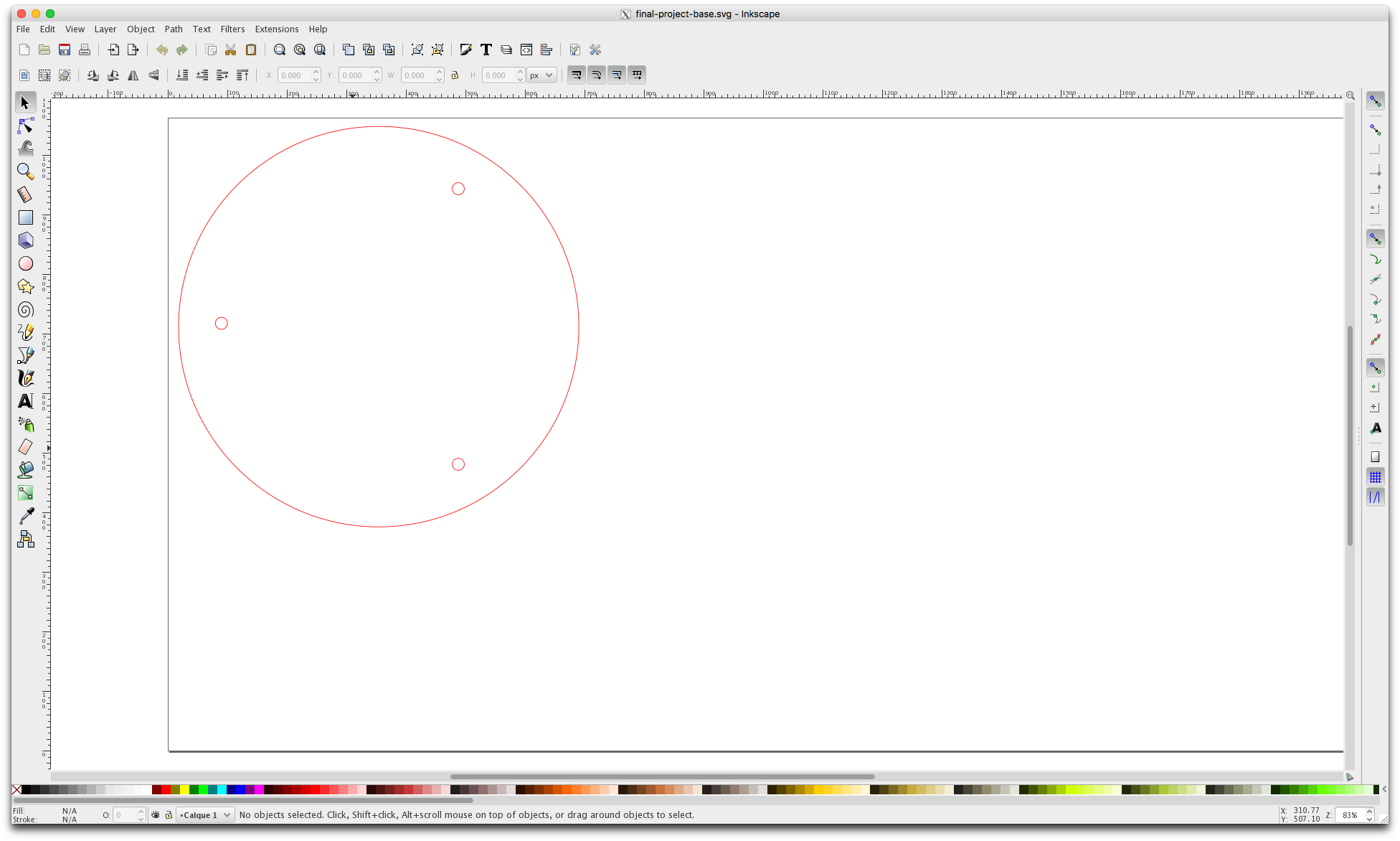
and the final result after assembly with 3 screws:
The files for this new box are available below:
- STP file for the final box final-project-final-box.stp
- STL file for the final box final-project-final-box.stl
- SVG file of the base plate for the final box final-project-base.svg
All the files can be downloaded on the final project summary page.