Networking and Communications
Assignment for this week
- Design and build a wired &/or wireless network connecting at least two processors
- Link to this week’s homeworkpage
The boards
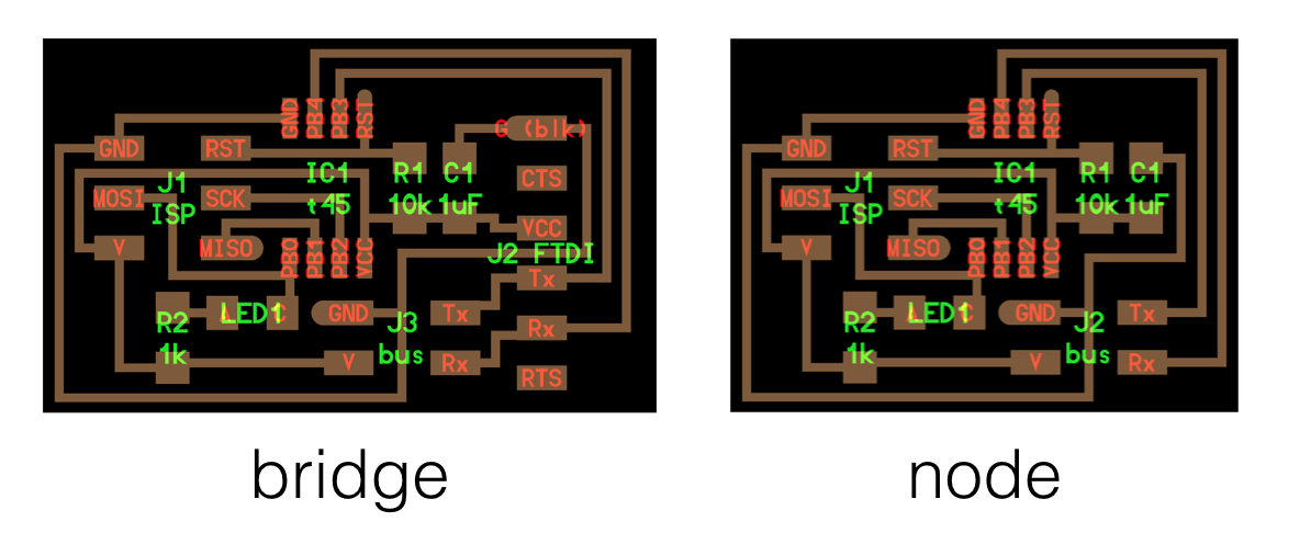
In class, we were shown an example of a network connecting a host computer to node boards through a bridge board using serial communication. The boards are based on an ATTiny45 microcontroller with a 6 pin header for ISP programming, a 10k resistor between RST and Vcc and 1uf capacitor for decoupling. PB0 is connected through a LED and 1k limiting current resistor to Vcc. Depending on the state of PB0, the LED can shine or not.
Both the bridge and the node boards have a 4 pin header (V, GND, Tx, Rx). The serial network is created by connecting all the 4 pins in series: Bridge > Node 1 > node 2 > node 3... The bridge has an additionnal 6 pin FDTI header to talk to the host computer. A Tx signal from the host will thus propage to all the nodes including the bridge which can be considered as node 0. In the same way a Rx signal from a node will propagate on the serial bus through all the nodes to the bridge and the host.
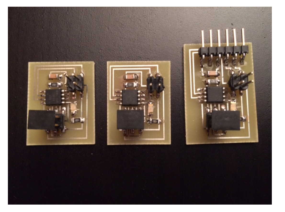
I made one bridge and two node boards. Of course I thoroughly checked all the solder joints and found a couple of bad joints that needed to be fixed. I had a moment of hesitation on the LED, checked the datasheet. Here you can see the result: the two nodes and the bridge.
IPS programming
I used the hello.bus.45.c code provided by Neil to ISP program my boards using my USBTiny programmer. The program is designed to that each board has an identifier. In the code, this is set by
#define node_id '0'Besides the usual functions get_char, put_char and put_string for reading and writing on the serial bus, the main part of the program is the following:
void flash() {
   //
   // LED flash delay
   //
   clear(led_port, led_pin);
   led_delay();
   set(led_port, led_pin);
   }

int main(void) {
   //
   // main
   //
   static char chr;
   //
   // set clock divider to /1
   //
   CLKPR = (1 << CLKPCE);
   CLKPR = (0 << CLKPS3) | (0 << CLKPS2) | (0 << CLKPS1) | (0 << CLKPS0);
   //
   // initialize output pins
   //
   set(serial_port, serial_pin_out);
   input(serial_direction, serial_pin_out);
   set(led_port, led_pin);
   output(led_direction, led_pin);
   //
   // main loop
   //
   while (1) {
      get_char(&serial_pins, serial_pin_in, &chr);
      flash();
      if (chr == node_id) {
         output(serial_direction, serial_pin_out);
         static const char message[] PROGMEM = "node ";
         put_string(&serial_port, serial_pin_out, (PGM_P) message);
         put_char(&serial_port, serial_pin_out, chr);
         put_char(&serial_port, serial_pin_out, 10); // new line
         led_delay();
         flash();
         input(serial_direction, serial_pin_out);
         }
      }
   }
Each node listens to the serial bus. If a character chr is received and corresponds to the node id "n", the node replies by sendind "node n" on the serial bus (this can be check on the terminal on the host computer) and then by flashing the LED with the function flash().
I programmed the boards by connecting my USBTiny programmer and a board using the 6 pin ribbon ISP cable and using the following command (after having changed the id in the .c code, '0' for the bridge, '1' and '2' for the nodes):
$make -f hello.bus.45.make program-usbtinyI obtained the following result for the first board (and essentially the same for the two others)
avr-gcc -mmcu=attiny45 -Wall -Os -DF_CPU=8000000 -I./ -o hello.bus.45.out hello.bus.45.c
avr-objcopy -O ihex hello.bus.45.out hello.bus.45.c.hex;\
	avr-size --mcu=attiny45 --format=avr hello.bus.45.out
AVR Memory Usage
----------------
Device: attiny45

Program:     768 bytes (18.8% Full)
(.text + .data + .bootloader)

Data:          4 bytes (1.6% Full)
(.data + .bss + .noinit)


avrdude -p t45 -P usb -c usbtiny -U flash:w:hello.bus.45.c.hex

avrdude: AVR device initialized and ready to accept instructions

Reading | ################################################## | 100% 0.00s

avrdude: Device signature = 0x1e9206
avrdude: NOTE: "flash" memory has been specified, an erase cycle will be performed
         To disable this feature, specify the -D option.
avrdude: erasing chip
avrdude: reading input file "hello.bus.45.c.hex"
avrdude: input file hello.bus.45.c.hex auto detected as Intel Hex
avrdude: writing flash (768 bytes):

Writing | ################################################## | 100% 1.18s

avrdude: 768 bytes of flash written
avrdude: verifying flash memory against hello.bus.45.c.hex:
avrdude: load data flash data from input file hello.bus.45.c.hex:
avrdude: input file hello.bus.45.c.hex auto detected as Intel Hex
avrdude: input file hello.bus.45.c.hex contains 768 bytes
avrdude: reading on-chip flash data:

Reading | ################################################## | 100% 1.42s

avrdude: verifying ...
avrdude: 768 bytes of flash verified

avrdude: safemode: Fuses OK (H:FF, E:DF, L:62)

avrdude done.  Thank you.
I then connected the bridge and the node with jumper cables because I did'nt have the 4 pin ribbon cable with 3 connectors and I used a terminal.
Bluetooth communication between a microcontroller and a smartphone
For my final project, I used bluetooth low energy communication between a fabduino and a smartphone. More on that on my project development page.