Output Devices
Assignment for this week
- Add an output device to a microcontroller board you've designed and program it to do something
- Link to this week’s homeworkpage
This page is organized as follows:
Hello LCD
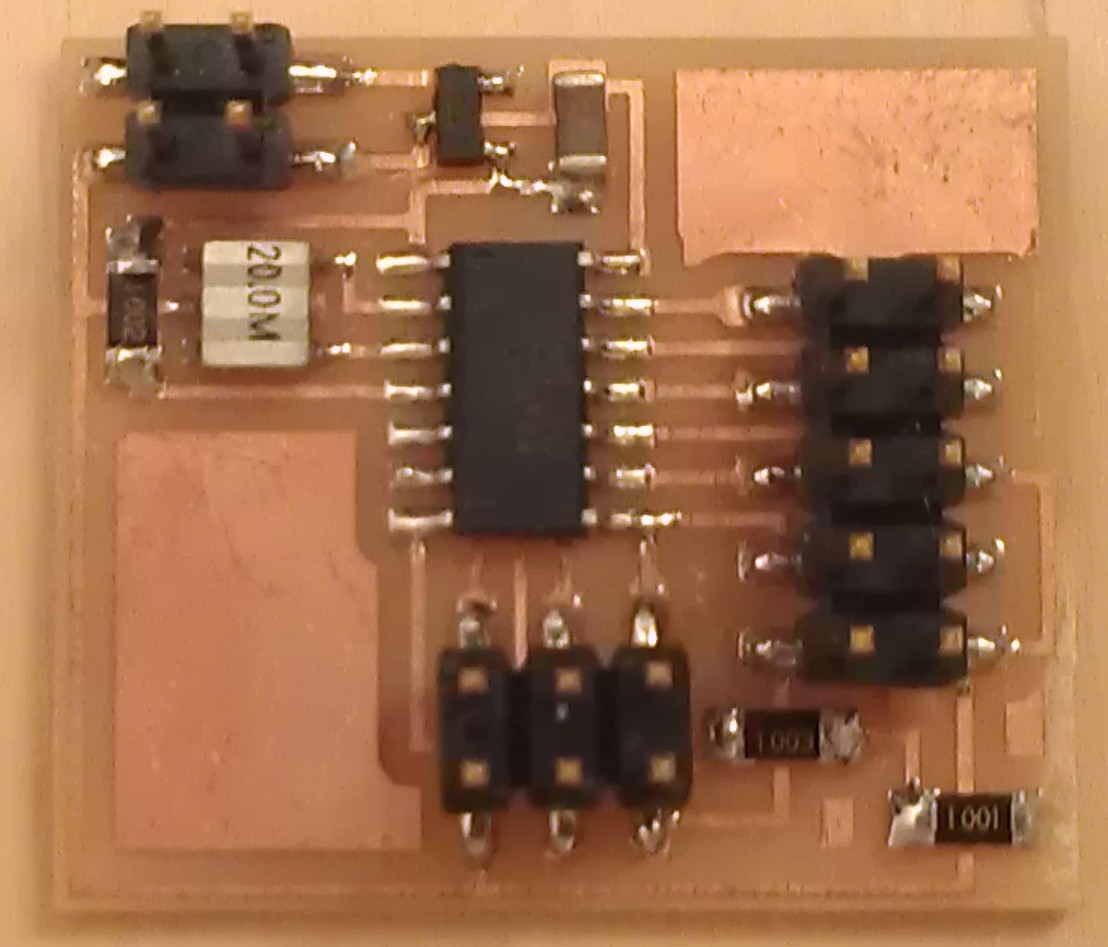
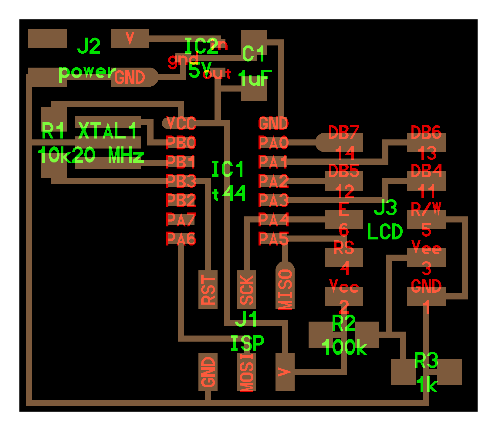
I decided to try the hello.LCD.44 board. The board includes a ATTiny44 with its 6 pin ISP programming header and a 10 pin header connected to a LDC display device.
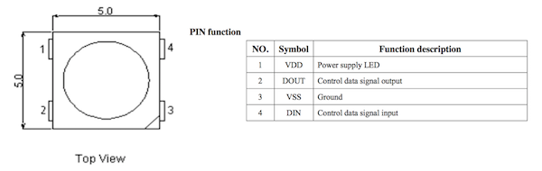
The Digikey link to the device correspond to a LCD display device with a serial interface and not to the one used in the C code provided by Neil. Instead the right device is a LCD module 1602A-1 with the corresponding pinout:

According to the C code and the 10 pin header on the board it is necessary to connect to pin DB4-5-6-7:
//
// hello.LCD.44.c
//
// LCD hello-world
//
// set lfuse to 0x5E for 20 MHz xtal
//
// Neil Gershenfeld
// 11/14/10
//
// (c) Massachusetts Institute of Technology 2010
// This work may be reproduced, modified, distributed,
// performed, and displayed for any purpose. Copyright is
// retained and must be preserved. The work is provided
// as is; no warranty is provided, and users accept all
// liability.
//

#include <avr/io.h>
#include <util/delay.h>
#include <avr/pgmspace.h>

#define output(directions,pin) (directions |= pin) // set port direction for output
#define set(port,pin) (port |= pin) // set port pin
#define clear(port,pin) (port &= (~pin)) // clear port pin
#define pin_test(pins,pin) (pins & pin) // test for port pin
#define bit_test(byte,bit) (byte & (1 << bit)) // test for bit set

#define LCD_port PORTA
#define LCD_direction DDRA
#define DB7 (1 << PA0)
#define DB6 (1 << PA1)
#define DB5 (1 << PA2)
#define DB4 (1 << PA3)
#define E (1 << PA4)
#define RS (1 << PA5)

#define long_delay() _delay_ms(1000) // delay before redraw
#define lcd_delay() _delay_ms(10) // delay between commands
#define strobe_delay() _delay_us(1) // delay for strobe

//
// lcd_putchar
//    put character in lcdbyte
//
void lcd_putchar(char lcdbyte) {
   //
   // set RS for data
   //
   set(LCD_port, RS);
   //
   // output high nibble
   //
   if bit_test(lcdbyte, 7)
      set(LCD_port, DB7);
   else
      clear(LCD_port, DB7);
   if bit_test(lcdbyte, 6)
      set(LCD_port, DB6);
   else
      clear(LCD_port, DB6);
   if bit_test(lcdbyte, 5)
      set(LCD_port, DB5);
   else
      clear(LCD_port, DB5);
   if bit_test(lcdbyte, 4)
      set(LCD_port, DB4);
   else
      clear(LCD_port, DB4);
   //
   // strobe E
   //
   strobe_delay();
   set(LCD_port, E);
   strobe_delay();
   clear(LCD_port, E);
   //
   // wait
   //
   lcd_delay();
   //
   // output low nibble
   //
   if bit_test(lcdbyte, 3)
      set(LCD_port, DB7);
   else
      clear(LCD_port, DB7);
   if bit_test(lcdbyte, 2)
      set(LCD_port, DB6);
   else
      clear(LCD_port, DB6);
   if bit_test(lcdbyte, 1)
      set(LCD_port, DB5);
   else
      clear(LCD_port, DB5);
   if bit_test(lcdbyte, 0)
      set(LCD_port, DB4);
   else
      clear(LCD_port, DB4);
   //
   // strobe E
   //
   strobe_delay();
   set(LCD_port, E);
   strobe_delay();
   clear(LCD_port, E);
   //
   // wait and return
   //
   lcd_delay();
   }
//
// lcd_putcmd
//    put command in lcdbyte
//
void lcd_putcmd(char lcdbyte) {
   //
   // clear RS for command
   //
   clear(LCD_port, RS);
   //
   // output command bits
   //
   PORTA = lcdbyte;
   //
   // strobe E
   //
   strobe_delay();
   set(LCD_port, E);
   strobe_delay();
   clear(LCD_port, E);
   //
   // wait and return
   //
   lcd_delay();
   }
//
// lcd_putstring
//    put a null-terminated string in flash
//
void lcd_putstring(PGM_P message) {
   static uint8_t index;
   static char chr;
   index = 0;
   while (1) {
      chr = pgm_read_byte(&(message[index]));
      if (chr == 0)
         return;
      lcd_putchar(chr);
      ++index;
      }
   }
//
// lcd_init
//    initialize the LCD
//
void lcd_init() {
   //
   // power-up delay
   //
   lcd_delay();
   //
   // initialization sequence
   //
   lcd_putcmd(DB5+DB4);
   lcd_putcmd(DB5+DB4);
   lcd_putcmd(DB5+DB4);
   //
   // 4-bit interface
   //
   lcd_putcmd(DB5);
   //
   // two lines, 5x7 font
   //
   lcd_putcmd(DB5);
   lcd_putcmd(DB7);
   //
   // display on
   //
   lcd_putcmd(0);
   lcd_putcmd(DB7+DB6+DB5);
   //
   // entry mode
   //
   lcd_putcmd(0);
   lcd_putcmd(DB6+DB5);
   }

int main(void) {
   //
   // main
   //
   // set clock divider to /1
   //
   CLKPR = (1 << CLKPCE);
   CLKPR = (0 << CLKPS3) | (0 << CLKPS2) | (0 << CLKPS1) | (0 << CLKPS0);
   //
   // initialize LCD pins
   //
   clear(LCD_port, DB7);
   output(LCD_direction, DB7);
   clear(LCD_port, DB6);
   output(LCD_direction, DB6);
   clear(LCD_port, DB5);
   output(LCD_direction, DB5);
   clear(LCD_port, DB4);
   output(LCD_direction, DB4);
   clear(LCD_port, E);
   output(LCD_direction, E);
   clear(LCD_port, RS);
   output(LCD_direction, RS);
   //
   // initialize LCD
   //
   lcd_init();
   //
   // main loop
   //
   while (1) {
      //
      // go to zero position
      //
      lcd_putcmd(0);
      lcd_putcmd(DB5);
      //
      // print first line from flash
      //
      static const char line1[] PROGMEM = "Hello to";
      lcd_putstring((PGM_P) line1);
      //
      // move to second line
      //
      lcd_putcmd(DB7+DB6);
      lcd_putcmd(0);
      //
      // print second line from flash
      //
      static const char line2[] PROGMEM = "the world";
      lcd_putstring((PGM_P) line2);
      //
      // pause
      //
      long_delay();
      //
      // clear display
      //
      lcd_putcmd(0);
      lcd_putcmd(DB4);
      }
   }
I etched to board and soldered the different components.

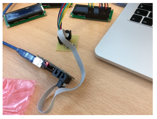
I programmed the board with my USBTiny programmer using:
$ make -f hello.LCD.44.make program-usbtinyAnd could see the text displayed on the LCD !

Hello RGB
I made the hello RGB board.

Update after 1st evaluation round
After 1st evaluation round, I was asked to design and make my own input board. Making, understanding and programming the boards seen in class was not enough. I decided to make a RGB output board with a WS2812b WS2812B RGB LED that integrates its own control circuit.
Adafruit has developped a convenient library to drive such LEDs that can be used with ATTiny MCUs. I decided to use a Tiny85 with 8k flash memory (enough to deal with the libary in an Arduinio IDE). I designed to board in KiCAD. The schematics in eeschema is the following:
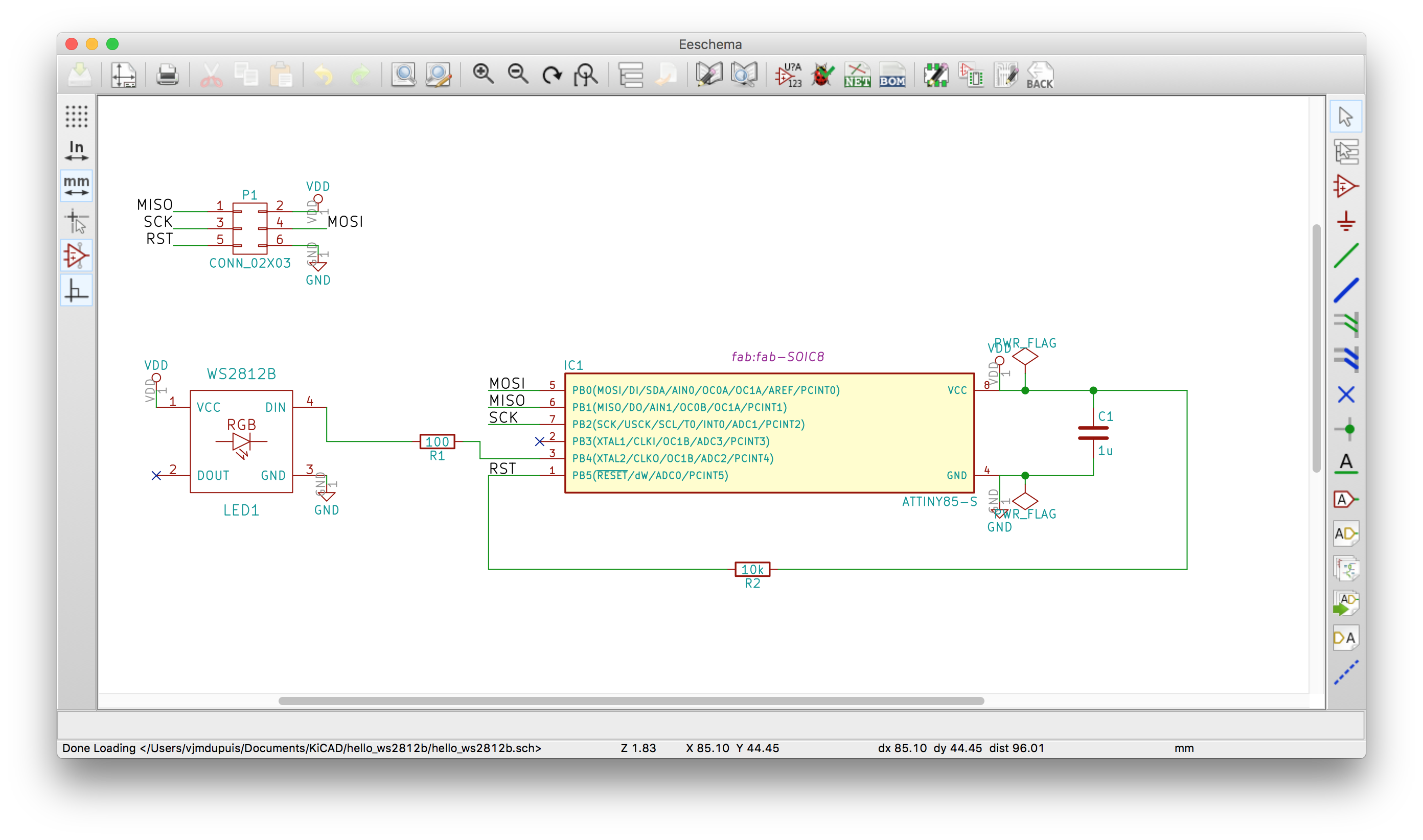
It includes the 6 pin connector for ISP programming, the 1 uF capacitor between the power line Vdd and ground and the 10k resistor between Reset and Vdd. A 100 ohms resistor is placed between the WS2812B input pin and the MCU output pin (PB4).
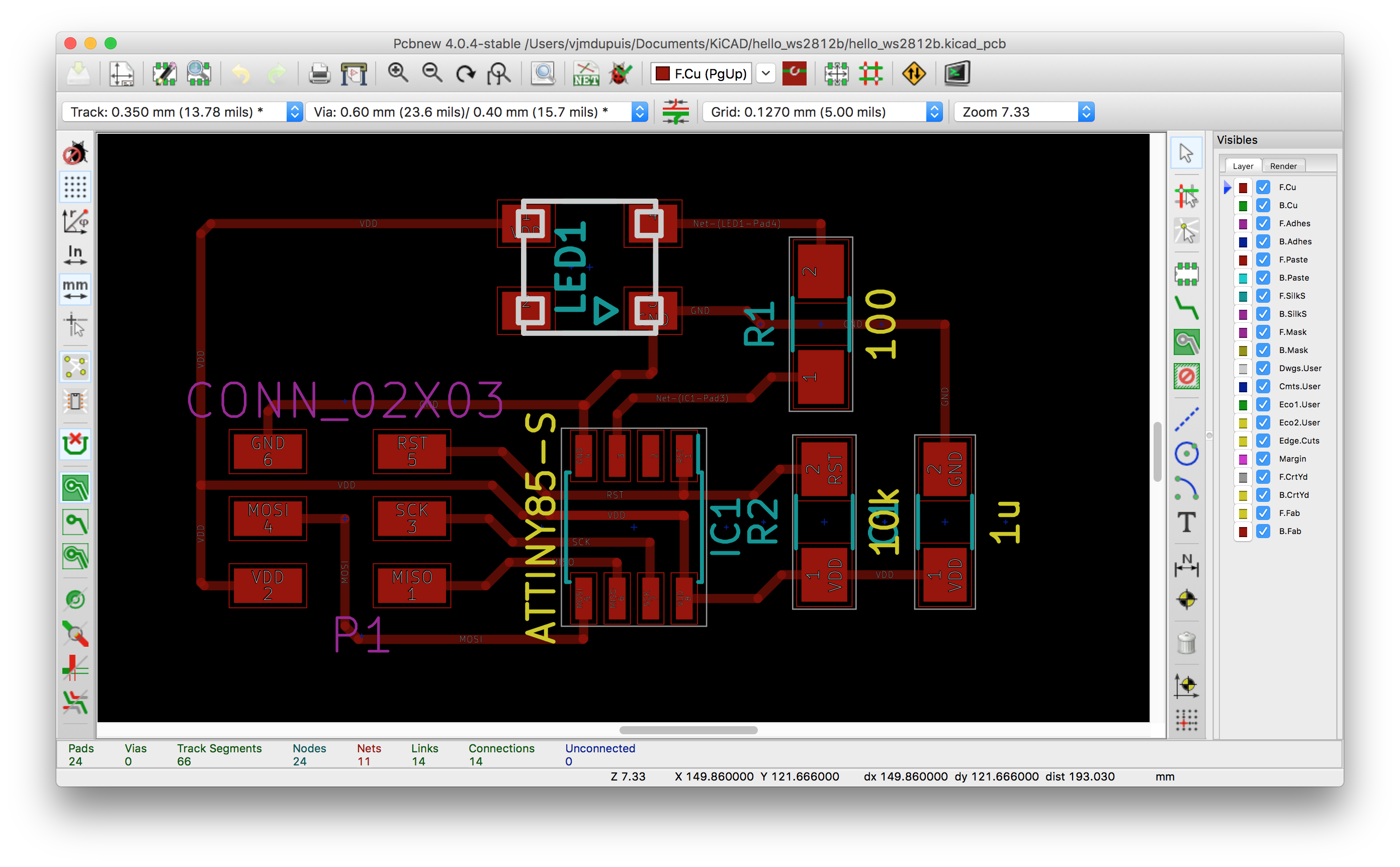
The routing in pcbnew is inspired from Neil's boards (at least for the traces connecting the ISP connector and the MCU):
I made the board using etching, soldered the parts, and checked the connections with a digital multimeter.

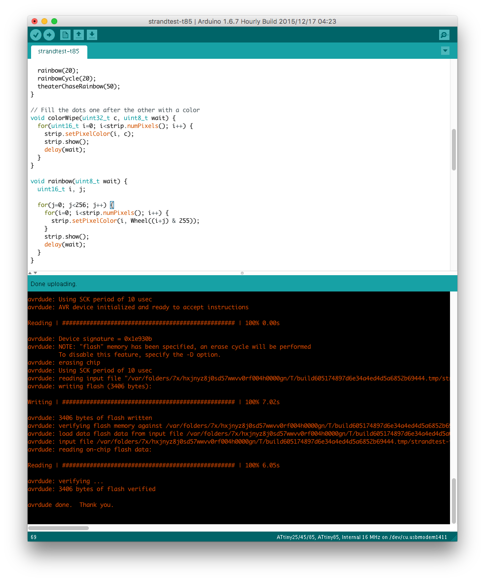
I then used my tinyISP programmer to program the board using the Arduino IDE (it is necessary to add the attiny board to the board manager following the procedure described here).

I uploaded the Arduino bootloader first and then after installing Neopixel library I uploaded the standtest example after modifying the PIN constant to fit my design (output PIN is pin 4 in my case):
#include <Adafruit_NeoPixel.h>
#ifdef __AVR__
  #include <avr/power.h>
#endif

#define PIN 4

// Parameter 1 = number of pixels in strip
// Parameter 2 = Arduino pin number (most are valid)
// Parameter 3 = pixel type flags, add together as needed:
//   NEO_KHZ800  800 KHz bitstream (most NeoPixel products w/WS2812 LEDs)
//   NEO_KHZ400  400 KHz (classic 'v1' (not v2) FLORA pixels, WS2811 drivers)
//   NEO_GRB     Pixels are wired for GRB bitstream (most NeoPixel products)
//   NEO_RGB     Pixels are wired for RGB bitstream (v1 FLORA pixels, not v2)
//   NEO_RGBW    Pixels are wired for RGBW bitstream (NeoPixel RGBW products)
Adafruit_NeoPixel strip = Adafruit_NeoPixel(1, PIN, NEO_GRB + NEO_KHZ800);

// IMPORTANT: To reduce NeoPixel burnout risk, add 1000 uF capacitor across
// pixel power leads, add 300 - 500 Ohm resistor on first pixel's data input
// and minimize distance between Arduino and first pixel.  Avoid connecting
// on a live circuit...if you must, connect GND first.

void setup() {
  // This is for Trinket 5V 16MHz, you can remove these three lines if you are not using a Trinket
  #if defined (__AVR_ATtiny85__)
    if (F_CPU == 16000000) clock_prescale_set(clock_div_1);
  #endif
  // End of trinket special code


  strip.begin();
  strip.show(); // Initialize all pixels to 'off'
}

void loop() {
  // Some example procedures showing how to display to the pixels:
  colorWipe(strip.Color(255, 0, 0), 50); // Red
  colorWipe(strip.Color(0, 255, 0), 50); // Green
  colorWipe(strip.Color(0, 0, 255), 50); // Blue
//colorWipe(strip.Color(0, 0, 0, 255), 50); // White RGBW
  // Send a theater pixel chase in...
  theaterChase(strip.Color(127, 127, 127), 50); // White
  theaterChase(strip.Color(127, 0, 0), 50); // Red
  theaterChase(strip.Color(0, 0, 127), 50); // Blue

  rainbow(20);
  rainbowCycle(20);
  theaterChaseRainbow(50);
}

// Fill the dots one after the other with a color
void colorWipe(uint32_t c, uint8_t wait) {
  for(uint16_t i=0; i<strip.numPixels(); i++) {
    strip.setPixelColor(i, c);
    strip.show();
    delay(wait);
  }
}

void rainbow(uint8_t wait) {
  uint16_t i, j;

  for(j=0; j< j++) {
    for(i=0; i<strip.numPixels(); i++) {
      strip.setPixelColor(i, Wheel((i+j) & 255));
    }
    strip.show();
    delay(wait);
  }
}

// Slightly different, this makes the rainbow equally distributed throughout
void rainbowCycle(uint8_t wait) {
  uint16_t i, j;

  for(j=0; j<256*5; j++) { // 5 cycles of all colors on wheel
    for(i=0; i< strip.numPixels(); i++) {
      strip.setPixelColor(i, Wheel(((i * 256 / strip.numPixels()) + j) & 255));
    }
    strip.show();
    delay(wait);
  }
}

//Theatre-style crawling lights.
void theaterChase(uint32_t c, uint8_t wait) {
  for (int j=0; j< j++) {  //do 10 cycles of chasing
    for (int q=0; q < 3; q++) {
      for (uint16_t i=0; i < strip.numPixels(); i=i+3) {
        strip.setPixelColor(i+q, c);    //turn every third pixel on
      }
      strip.show();

      delay(wait);

      for (uint16_t i=0; i < strip.numPixels(); i=i+3) {
        strip.setPixelColor(i+q, 0);        //turn every third pixel off
      }
    }
  }
}

//Theatre-style crawling lights with rainbow effect
void theaterChaseRainbow(uint8_t wait) {
  for (int j=0; j < 256; j++) {     // cycle all 256 colors in the wheel
    for (int q=0; q < 3; q++) {
      for (uint16_t i=0; i < strip.numPixels(); i=i+3) {
        strip.setPixelColor(i+q, Wheel( (i+j) % 255));    //turn every third pixel on
      }
      strip.show();

      delay(wait);

      for (uint16_t i=0; i < strip.numPixels(); i=i+3) {
        strip.setPixelColor(i+q, 0);        //turn every third pixel off
      }
    }
  }
}

// Input a value 0 to 255 to get a color value.
// The colours are a transition r - g - b - back to r.
uint32_t Wheel(byte WheelPos) {
  WheelPos = 255 - WheelPos;
  if(WheelPos < 85) {
    return strip.Color(255 - WheelPos * 3, 0, WheelPos * 3);
  }
  if(WheelPos < 170) {
    WheelPos -= 85;
    return strip.Color(0, WheelPos * 3, 255 - WheelPos * 3);
  }
  WheelPos -= 170;
  return strip.Color(WheelPos * 3, 255 - WheelPos * 3, 0);
}
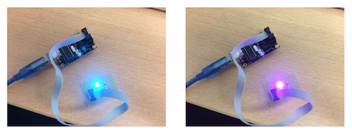
Upload finished ok and I could then see the color changes:
The kicad files, ATTiny firmware and python script can be downloaded below (or in the section Files to download, top right panel):
- kicad .pro file: hello_ws2812b.pro
- schematics: hello_ws2812b.sch
- board: hello_ws2812b.kicad_pcb
- firmware (arduino sketch): firmware.ino