Embedded Networking and Communication
We are free to choose any way of communication for example serial or I2C. I chose to use I2C to fulfill the assignment.
Designing a new board
- I decided to make a new board using Attiny84A microcontroller and use 3 other boards I have developed for previous assignments
- I started by reading the datasheet to know the pinout of the chip and how to properly connect them.
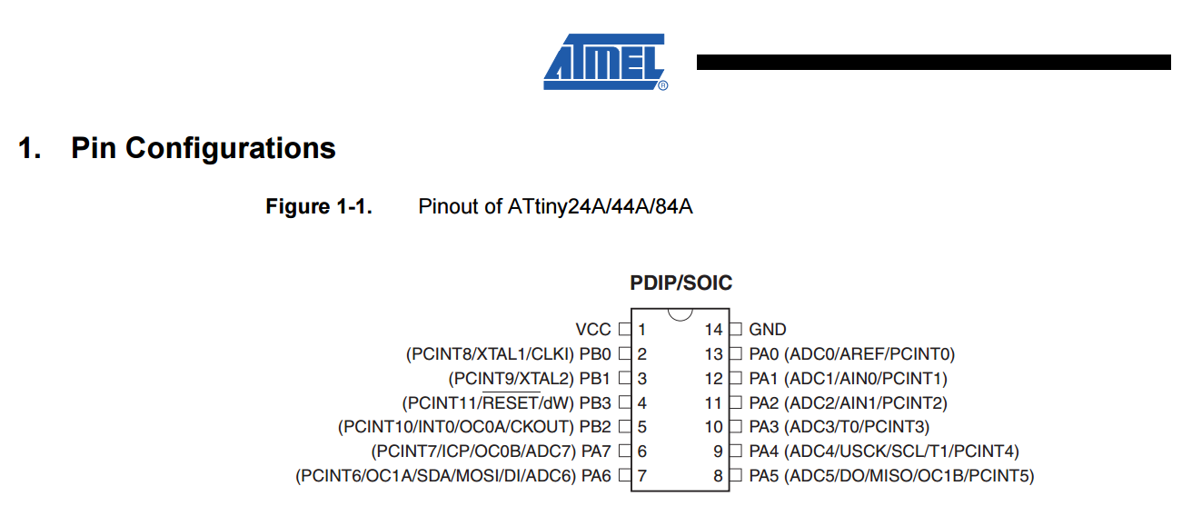
- After knowing the Pinout of the chip I decided to expose all of the I/O pins and connect one of the outputs to an LED through a resistor. Of course I also exposed the SDA and SCL pins which are the I2C pins. Finally I connected a 20Mhz crystal to XTal1 and XTal2 with 22 pf capacitors.
- Based on the datasheet I used eagle to draw the schematic of my board and then I switched to routing the board. How I did that is explained in detail throughout previous assignments. After being done with all that I exported the board as a png and got the final images needed for milling.


- As always I used MDX-40A milling machine along with fabmodules to mill the board. I used more or less the same settings that I use usually as mentioned in previous documentation apart from the XYZ coordinates of course.
- Speed-->4
- Number of offsets-->4
- Offset overlap-->55
- Cut depth-->0
- Tool diameter-->0.2
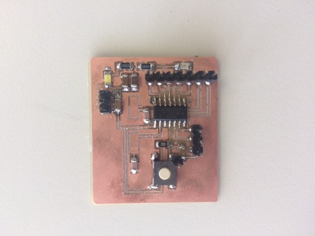
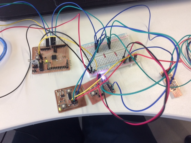
-This is how it looked like after milling and soldering.
- I burned the bootloader to the chip using an arduino uno and then uploaded a simple blink sketch to make sure it's working


- Next step was to connect the board as a slave to a master. I decided to use a modified satsha kit as a master and 2 other boards as slave 1 , slave 2 and the new one I developped as slave 3
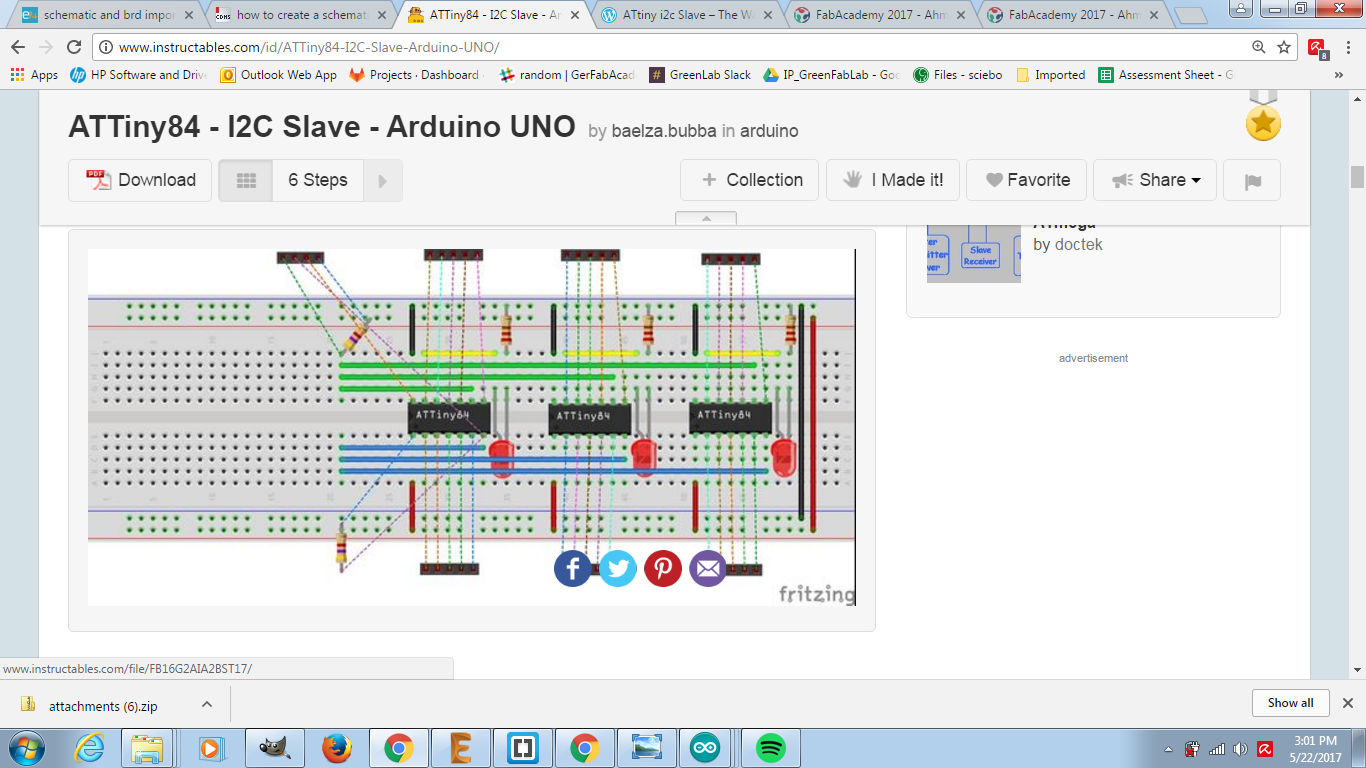
- I followed this tutorial on instuctables which led me to another one . Eventually after following these tutorials I was able to add the modified TinyS library to Arduino which allowed me to program the Attiny microcontrollers as slaves
- I first programmed all the slaves using the modifies Satsha kit and then I programmed it to be a master using FTDI cable and arduino IDE. each slave should have it's unique address I used addresses from 1 to 3
- Finally I connected all the SDA pins of the slaves to the SDA of the master and the same for SCL. Also all the SDA and SCL pins of the slaves should be connected to vcc via a 4.7K ohm, It's essential for these boards to work
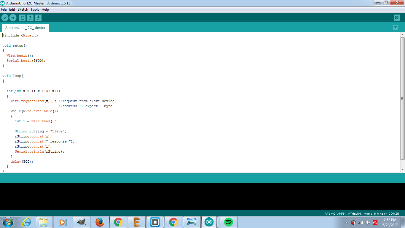
- Master code
 #include

void setup()
{
  Wire.begin();
  Serial.begin(9600);
}

void loop()
{

  for(int x = 1; x < 4; x++)
  {
    Wire.requestFrom(x,1); //request from slave device
                           //address 1. expect 1 byte
    while(Wire.available())
    {
      int i = Wire.read();

      String rString = "Slave";
      rString.concat(x);
      rString.concat(" response ");
      rString.concat(i);
      Serial.println(rString);
    }
    delay(500);
  }
}
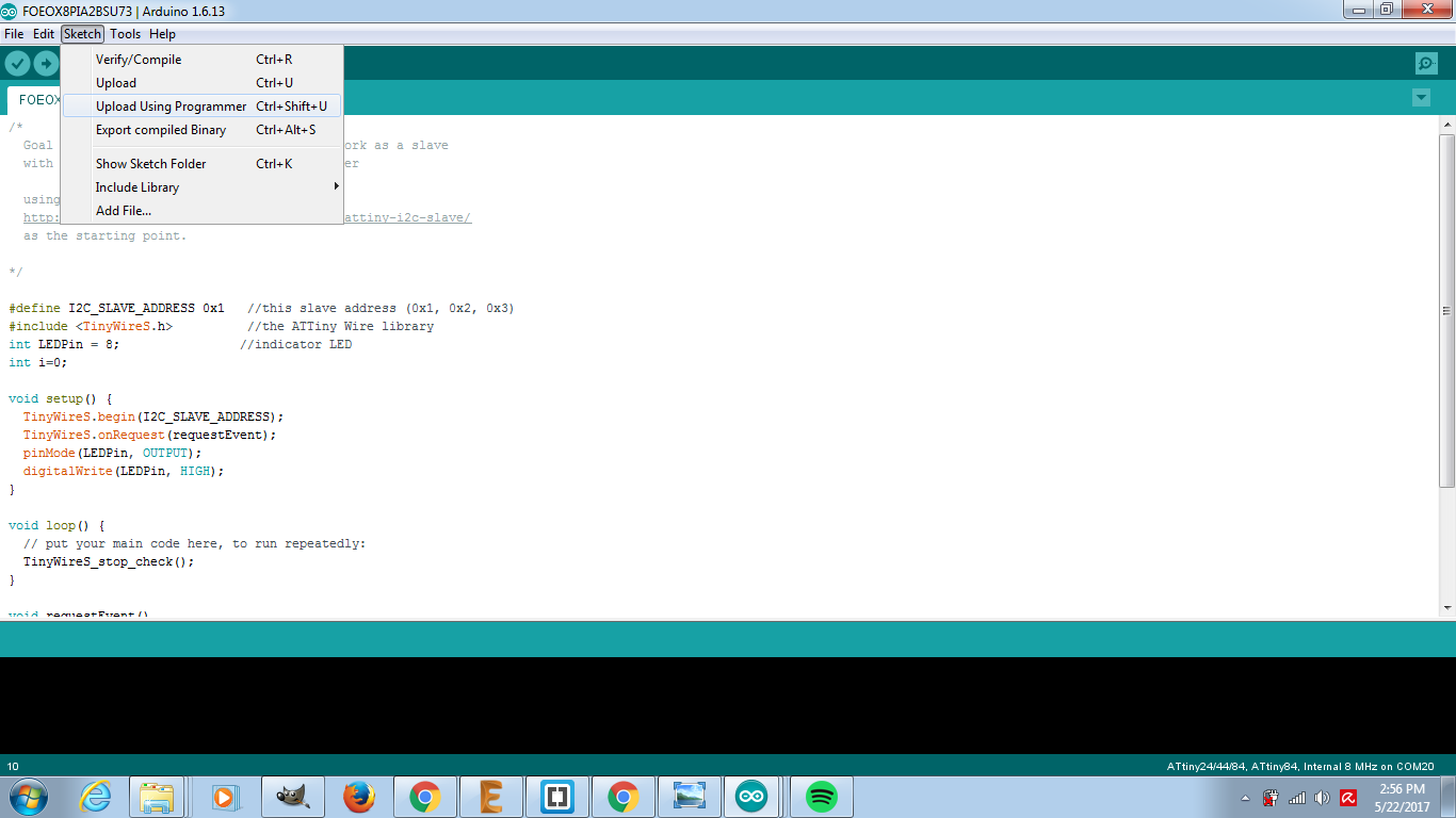
- Slaves' code
#define I2C_SLAVE_ADDRESS 0x1   //this slave address (0x1, 0x2, 0x3)
#include           //the ATTiny Wire library
int LEDPin = 8;                //indicator LED
int i=0;

void setup() {
  TinyWireS.begin(I2C_SLAVE_ADDRESS);
  TinyWireS.onRequest(requestEvent);
  pinMode(LEDPin, OUTPUT);
  digitalWrite(LEDPin, HIGH);
}

void loop() {
  // put your main code here, to run repeatedly:
  TinyWireS_stop_check();
}

void requestEvent()
{
  if(i%2==0)
  {digitalWrite(LEDPin, LOW);}
  else
  {digitalWrite(LEDPin, HIGH);}
  TinyWireS.send(i);
  i++;
}

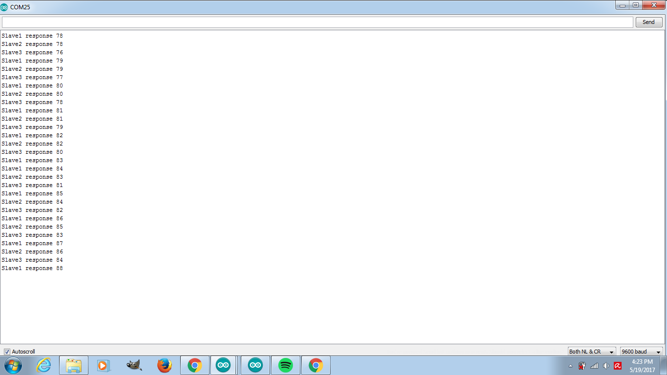
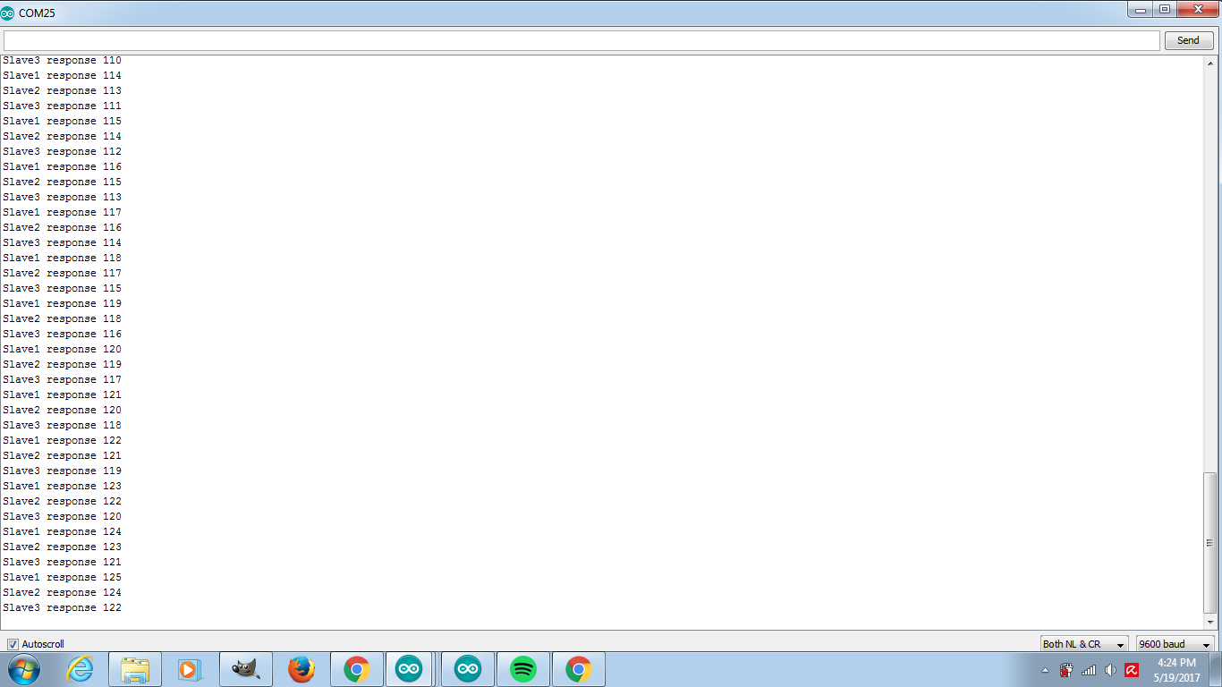
Final product
- This is how the serial monitor looked like. The code I uploaded is very simple it just pings one slave at a time and then the next and so on