
Electronics production
The FabISP board is a programmer board that can be used to program other microcontrolled boards.
PCB Fabrication

Milling:
-I used a Rolland MDX-40 machine along with fabmodules to control it.
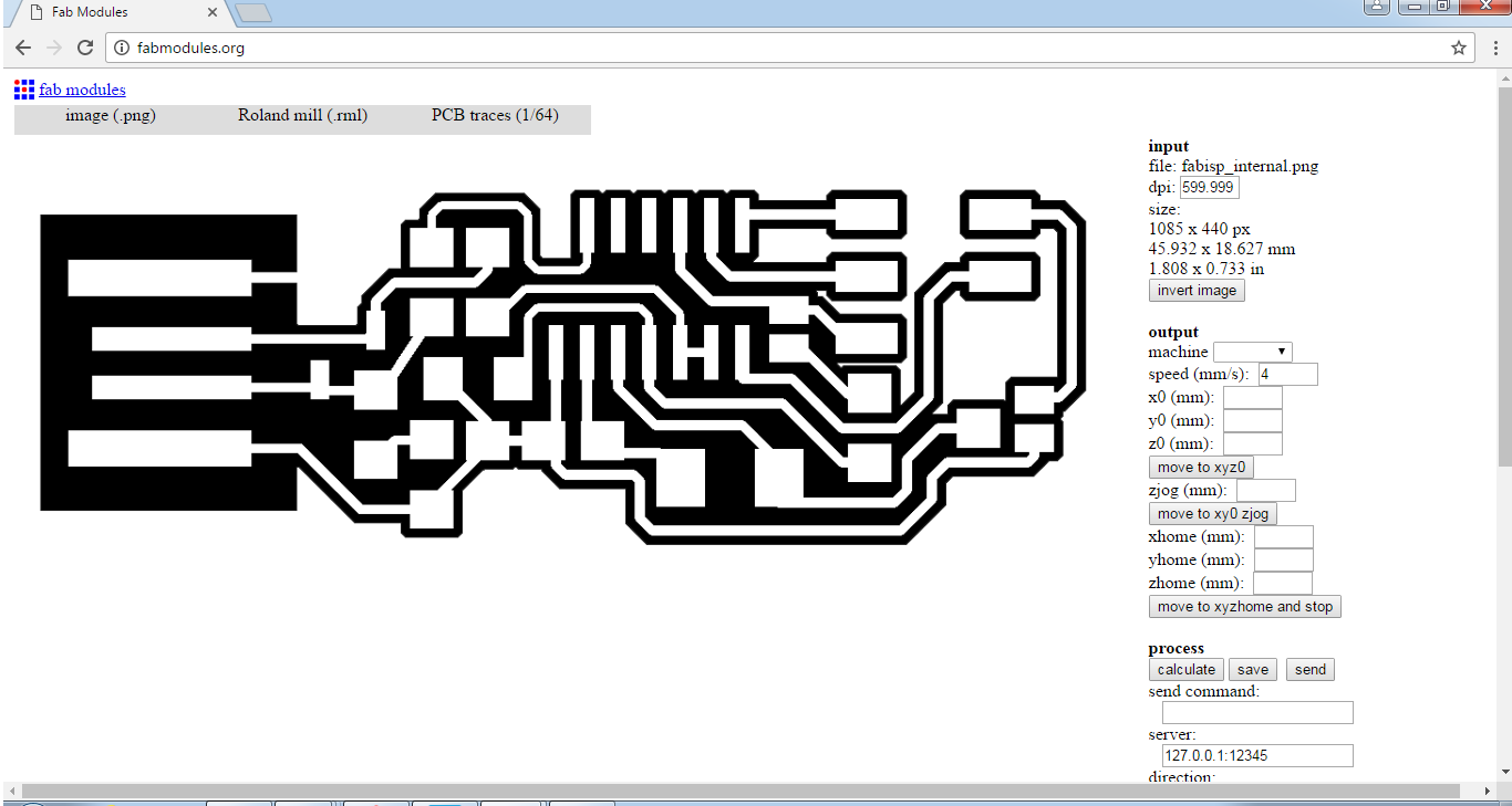

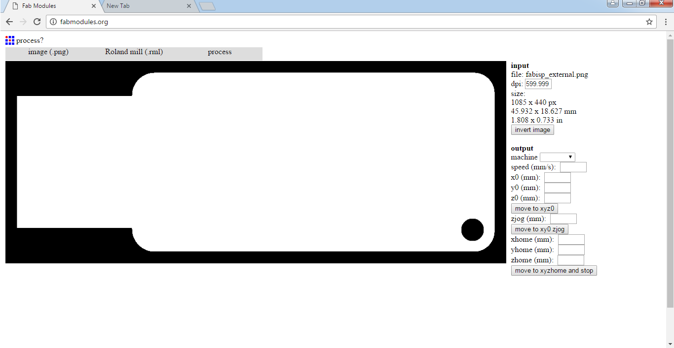
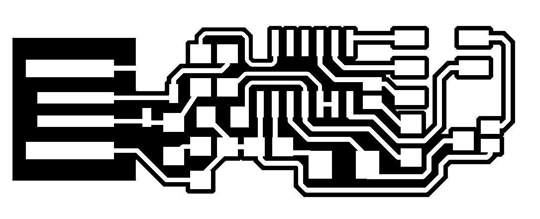
-First of all I connected to FabModules using the IP address of 127.0.0.1:12345 and then imported the image to it.

-I chose my Image and pressed Ok.
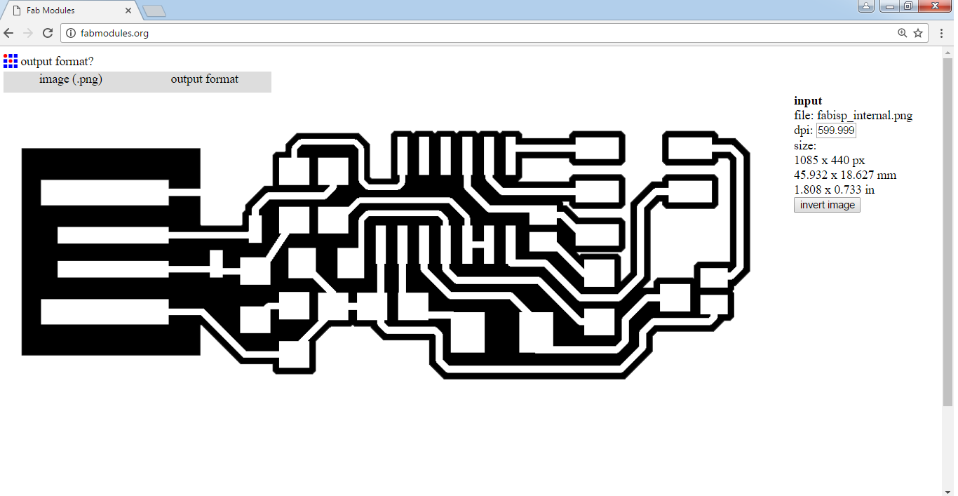
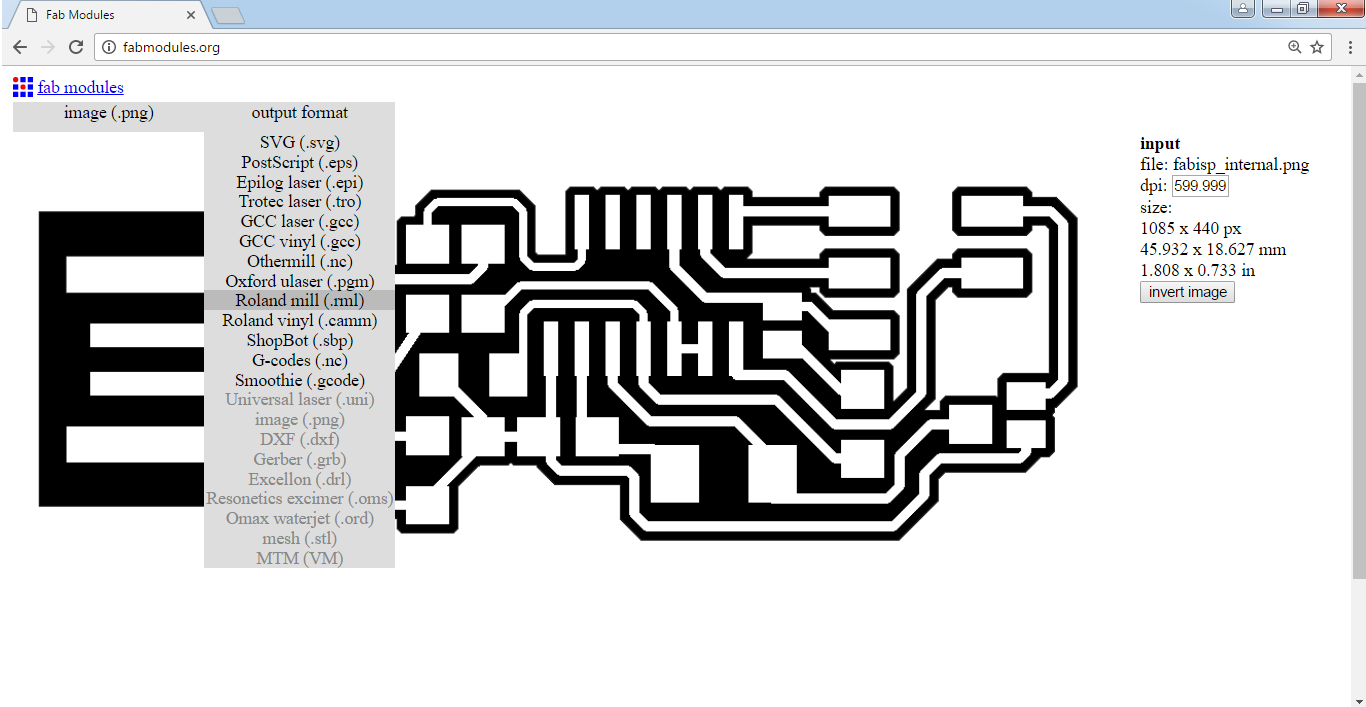
-Next thing to to is to choose the machine type by setting the output format, I chose Roland mill.
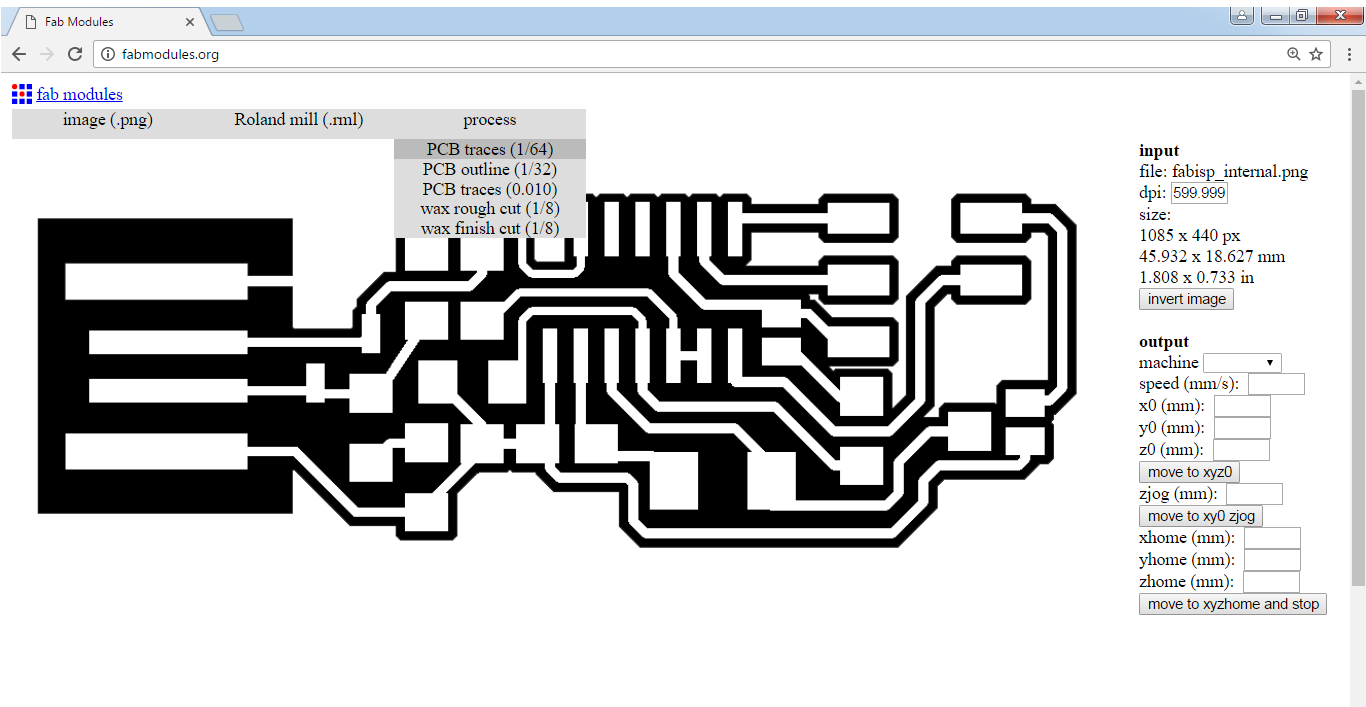
-I then choose the process type of 1/64 for PCB traces.
-Here are the settings I used for the internal paths:
-Machine: MDX40
-Speed: 6
-X0: -65
-Y0: -35
-Z0: -96.828
-ZJog: 0 (This has to be set to zero everytime the Z position is changed before moving the machine otherwise it is going to make the machine unresponsive)
-Send command: mod_lp.py /dev/usb/lp0
-Server: 127.0.0.1:12345
-Cut depth: 0.0
-Tool diameter: 0.2
-Number of offsets: 4
-Offset overlap: 60
Finally I pressed Calculate and that's what I got


-I sent the job to the machine and after almost 40 minutes the traces were done and Next I had to launch the other job of cutting the board out.
-First I uploaded the image for the cut
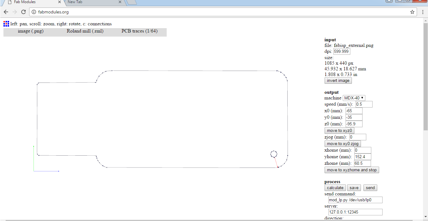
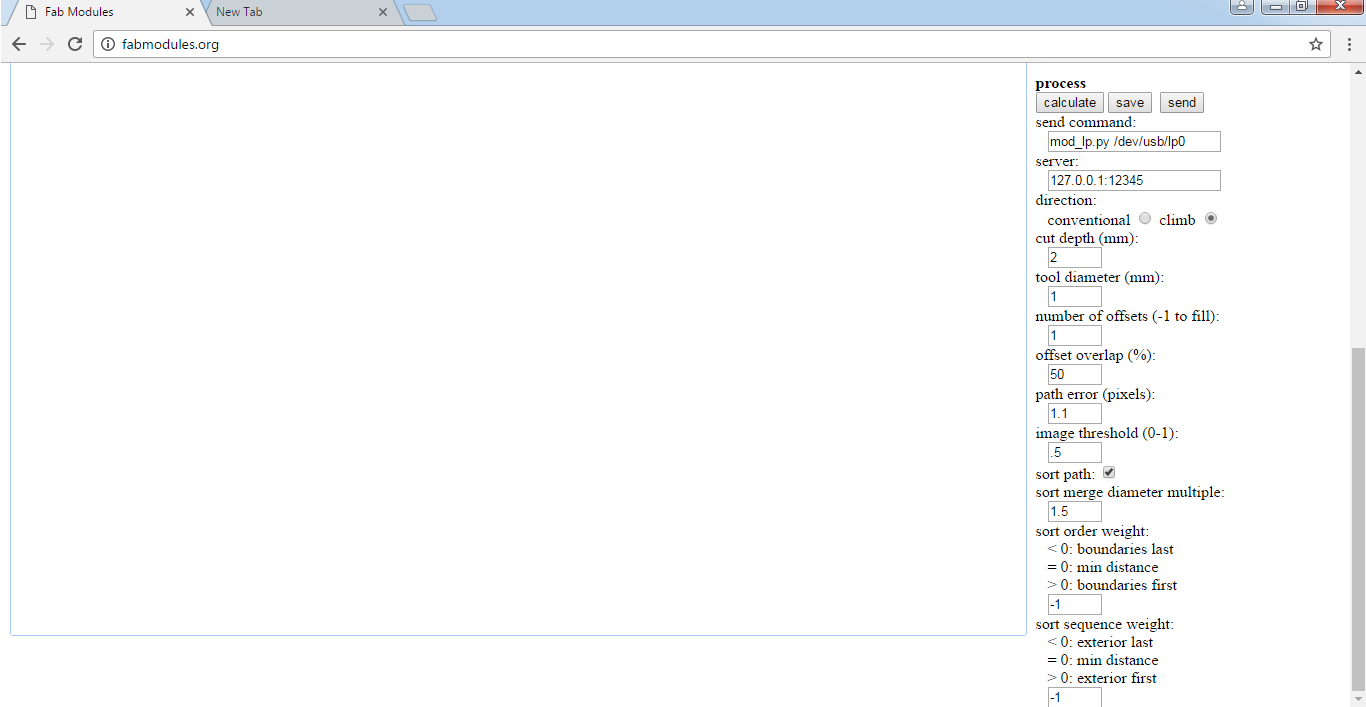
-Here are the settings for the cut:
-Machine: MDX40
-Speed: 0.5
-X0: -65
-Y0: -35
-Z0: -95.9
-ZJog: 0 (Again this has to be set to zero everytime the Z position is changed before moving the machine otherwise it is going to make the machine unresponsive)
-Send command: mod_lp.py /dev/usb/lp0
-Server: 127.0.0.1:12345
-Cut depth: 2.0
-Tool diameter: 1
-Number of offsets: 1
Finally I pressed Calculate and then sent the job to the machine
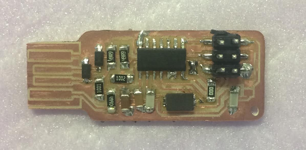
-The board is ready for the components to be soldered on it
All the components are SMD This means surface mount componets which have to be soldered on the surface of the board.
-Here are the components
1 ATTiny 44 microcontroller
1 Capacitor 1uF
1 Capacitor 0.1uF
2 Capacitor 10 pF
2 Resistor 100 ohm
1 Resistor 499 ohm
1 Resistor 1K ohm
1 Resistor 10K
3* 2 pin header
1 Cystal 20MHz
Soldering:
-I Like to use a very fine tip for soldering SMD compoenents along with a temperature of around 340°

-This is how it looked after soldering.

Programming:
I used an Arduino Uno board to program the ISP.
-The first step is to program the arduino to be a programmer this can be done bu uploading the sketch Arduino ISP to it. To do so go to File, Examples and choose Arduino ISP.

-Next step is to choose the port the Arduino is connected to by going to Tools, Port and choosing the right one.
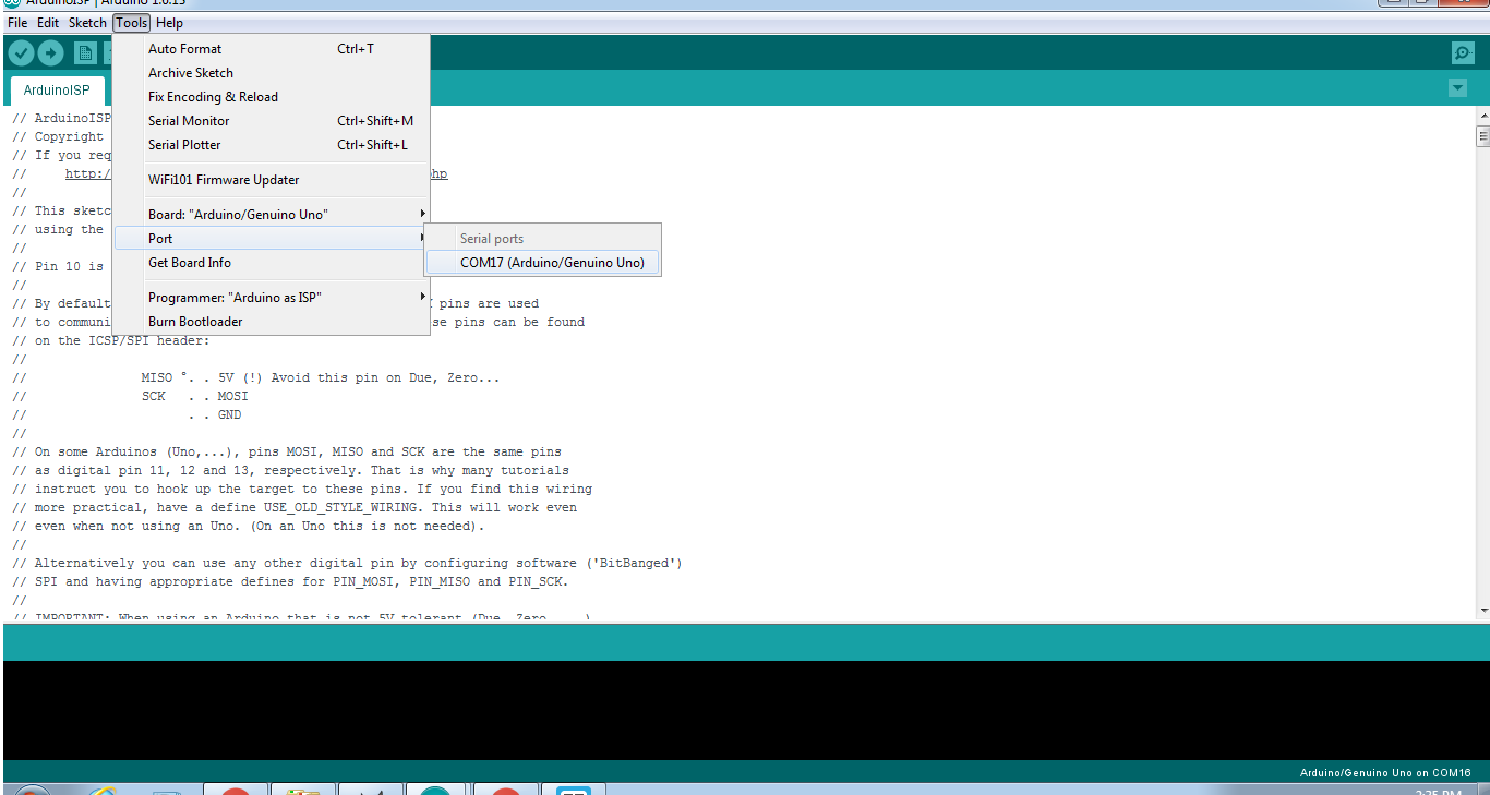
-Final step is to click Upload to upload the sketch to the board.

Now the Arduino is ready to programm the FabISP.
-I disconnected the Arduino from the laptop and connected the FabISP to the arduino as shown and then connected them to a Linux computer.

Getting and installing avrdude / GCC software and dependencies:
Open Terminal and type:
sudo apt-get install flex byacc bison gcc libusb-dev avrdudeThen type:
sudo apt-get install gcc-avr- type "y" when asked to do so by your system
Then type:
sudo apt-get install avr-libcThen type (may already be installed):
sudo apt-get install libc6-dev
Download and Unzip the Firmware:
Move to the desktop
cd ~/Desktop
Download the firmware from the Fab Academy Electronics Production page.
wget http://academy.cba.mit.edu/classes/embedded_programming/firmware.zip
Unzip the firmware
unzip firmware.zip-Make Changes:
Open the Makefile in the unzipped folder. Go to the line that says:
#AVRDUDE = avrdude -c usbtiny -p $(DEVICE) # edit this line for your programmer
AVRDUDE = avrdude -c avrisp2 -P usb -p $(DEVICE) # edit this line for your programmer
Now Type:
cd Desktop/firmware
Next you need to compile the firmware.
Type:
make cleanIf you are successful - you will see this response from the system:
rm -f main.hex main.lst main.obj main.cof main.list main.map main.eep.hexType:
main.elf *.o usbdrv/*.o main.s usbdrv/oddebug.s usbdrv/usbdrv.s
make hex
If you are successful - you will see this response from the system:
avr-gcc -Wall -Os -DF_CPU=20000000	 -Iusbdrv -I. -DDEBUG_LEVEL=0
-mmcu=attiny44 -c usbdrv/usbdrv.c -o usbdrv/usbdrv.o
avr-gcc -Wall -Os -DF_CPU=20000000	 -Iusbdrv -I. -DDEBUG_LEVEL=0
-mmcu=attiny44 -x assembler-with-cpp -c usbdrv/usbdrvasm.S -o usbdrv/usbdrvasm.o
avr-gcc -Wall -Os -DF_CPU=20000000	 -Iusbdrv -I. -DDEBUG_LEVEL=0
-mmcu=attiny44 -c usbdrv/oddebug.c -o usbdrv/oddebug.o
avr-gcc -Wall -Os -DF_CPU=20000000	 -Iusbdrv -I. -DDEBUG_LEVEL=0
-mmcu=attiny44 -c main.c -o main.o
avr-gcc -Wall -Os -DF_CPU=20000000	 -Iusbdrv -I. -DDEBUG_LEVEL=0
-mmcu=attiny44 -o main.elf usbdrv/usbdrv.o usbdrv/usbdrvasm.o usbdrv/oddebug.o
main.o
rm -f main.hex main.eep.hex
avr-objcopy -j .text -j .data -O ihex main.elf main.hex
avr-size main.hex
   text	   data	    bss	    dec	    hex	filename
      0	   2020	      0	   2020	    7e4	main.hex
Next you need edit the make file and change the line AVRDUDE = avrdude -c avrisp2 -P usb -p $(DEVICE) to AVRDUDE = avrdude -c stk500v1 -P /dev/ttyACM0 -b19200 -p $(DEVICE)
Next, you need to set the fuses so your board will use the external clock (crystal)
Type:
make fuseIf you are successful - you will see the following response from the system:
avrdude -c usbtiny -p attiny44  -U hfuse:w:0xDF:m -U lfuse:w:0xFF:m

avrdude: AVR device initialized and ready to accept instructions

Reading | ################################################## | 100% 0.01s

avrdude: Device signature = 0x1e9207
avrdude: reading input file "0xDF"
avrdude: writing hfuse (1 bytes):

Writing | ################################################## | 100% 0.00s

avrdude: 1 bytes of hfuse written
avrdude: verifying hfuse memory against 0xDF:
avrdude: load data hfuse data from input file 0xDF:
avrdude: input file 0xDF contains 1 bytes
avrdude: reading on-chip hfuse data:

Reading | ################################################## | 100% 0.00s

avrdude: verifying ...
avrdude: 1 bytes of hfuse verified
avrdude: reading input file "0xFF"
avrdude: writing lfuse (1 bytes):

Writing | ################################################## | 100% 0.01s

avrdude: 1 bytes of lfuse written
avrdude: verifying lfuse memory against 0xFF:
avrdude: load data lfuse data from input file 0xFF:
avrdude: input file 0xFF contains 1 bytes
avrdude: reading on-chip lfuse data:

Reading | ################################################## | 100% 0.00s

avrdude: verifying ...
avrdude: 1 bytes of lfuse verified

avrdude: safemode: Fuses OK

avrdude done.  Thank you.
Next you want to program the board to be an ISP.
Then type:
make programIf you are successful - you will see the following response from the system.
[sudo] password for "your user name":
avrdude -c usbtiny -p attiny44  -U flash:w:main.hex:i

avrdude: AVR device initialized and ready to accept instructions

Reading | ################################################## | 100% 0.01s

avrdude: Device signature = 0x1e9207
avrdude: NOTE: FLASH memory has been specified, an erase cycle will be performed
         To disable this feature, specify the -D option.
avrdude: erasing chip
avrdude: reading input file "main.hex"
avrdude: writing flash (2020 bytes):

Writing | ################################################## | 100% 5.68s


avrdude: 2020 bytes of flash written
avrdude: verifying flash memory against main.hex:
avrdude: load data flash data from input file main.hex:
avrdude: input file main.hex contains 2020 bytes
avrdude: reading on-chip flash data:

Reading | ################################################## | 100% 3.36s


avrdude: verifying ...
avrdude: 2020 bytes of flash verified

avrdude: safemode: Fuses OK

avrdude done.  Thank you.

avrdude -c usbtiny -p attiny44  -U hfuse:w:0xDF:m -U lfuse:w:0xFF:m

avrdude: AVR device initialized and ready to accept instructions

Reading | ################################################## | 100% 0.01s

avrdude: Device signature = 0x1e9207
avrdude: reading input file "0xDF"
avrdude: writing hfuse (1 bytes):

Writing | ################################################## | 100% 0.00s

avrdude: 1 bytes of hfuse written
avrdude: verifying hfuse memory against 0xDF:
avrdude: load data hfuse data from input file 0xDF:
avrdude: input file 0xDF contains 1 bytes
avrdude: reading on-chip hfuse data:

Reading | ################################################## | 100% 0.00s

avrdude: verifying ...
avrdude: 1 bytes of hfuse verified
avrdude: reading input file "0xFF"
avrdude: writing lfuse (1 bytes):

Writing | ################################################## | 100% 0.00s

avrdude: 1 bytes of lfuse written
avrdude: verifying lfuse memory against 0xFF:
avrdude: load data lfuse data from input file 0xFF:
avrdude: input file 0xFF contains 1 bytes
avrdude: reading on-chip lfuse data:

Reading | ################################################## | 100% 0.00s

avrdude: verifying ...
avrdude: 1 bytes of lfuse verified

avrdude: safemode: Fuses OK

avrdude done.  Thank you.
Next you want to do a final check to make sure the ISP is working
Type:
lsusbIf you are successful - you will see the following response from the system.
Bus 002 Device 002: ID 8087:0024 Intel Corp. Integrated Rate Matching Hub
Bus 002 Device 001: ID 1d6b:0002 Linux Foundation 2.0 root hub
Bus 001 Device 003: ID 13d3:5188 IMC Networks
Bus 001 Device 002: ID 8087:0024 Intel Corp. Integrated Rate Matching Hub
Bus 001 Device 001: ID 1d6b:0002 Linux Foundation 2.0 root hub
Bus 004 Device 001: ID 1d6b:0003 Linux Foundation 3.0 root hub
Bus 003 Device 004: ID 2a03:0043 dog hunter AG Arduino Uno Rev3
Bus 003 Device 002: ID 1d57:fa20 Xenta
Bus 003 Device 010: ID 1781:0c9f Multiple Vendors USBtiny
Bus 003 Device 001: ID 1d6b:0002 Linux Foundation 2.0 root hub
In one line of the lines you should find "Multiple Vendors USBtiny" in my case it was the one before last.

Problems:
1- I had a prblem with milling because the bed of the machine was not perfectly even so as shown in the picture on corner was over milled while the opposie one was under milled so I had to adjust it and then relaunched the job.

2- I tried to use Windows OS to program the board but I could't. I spent couple of hours trying to do this but eventually I decided to use an Ubuntu computer from my friend Dima .
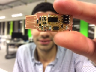
Final product:
Hero shot: