FINAL PROJECT - ULTIMAKER FILAMENT MEASURING INSTRUMENT
U-FMI
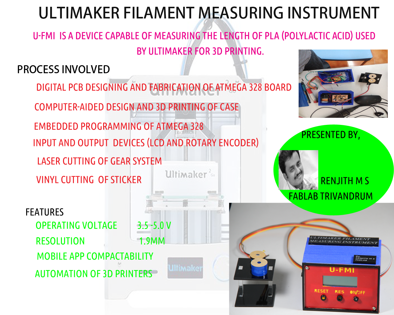
- U-FMI ie ULTIMAKER FILAMENT MEASURING INSTRUMENT is a device capable of measuring the Length of PLA (polylactic acid) used by ultimaker for 3D printing.
My first idea is to make a smart guide ,but considering the complexity involved I changed my idea .U-FMI stands for Ultimaker filament measuring instrument. U-FMI consists of a rotary encoder unit connected to microcontroller which measures the length of PLA used for 3D-printing .The process used is simple,the moving PLA rotates the rotary encoder and the rotation is converted back to linear scale using the microcontroller.The value is displayed in LCD display.
U-FMI
My work has been licensed under Creative Commons Attribution-NonCommercial 4.0 International License.
It was a great experiance of hard work during the last 3 week,which made me confident of converting my ideas to product development. I started the process by testing in arduino board and finally completed my project .The vedio slide for my project is made using Windows Movie Maker. I enjoyed the process of vedio making.The Poster for my project is being done in adobe photoshop. Both the slide and vedio presentation enhanced my confidence level.
PROPOSED IDEA AND TESTING
I got the idea of making U-FMI from instructables ,for more details click here.
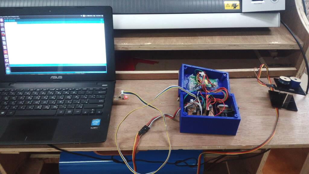
I started my work of making U-FMI with arduino board,rotary encoder and LCD display with a simple arduino code and it worked as expected. The block diagrom of my U-FMI is given below.The arduino setup is also provided beside.

The draft sketch of my project is given above.It consists of microcontroller,LCD display,Rotary encoder and switches.
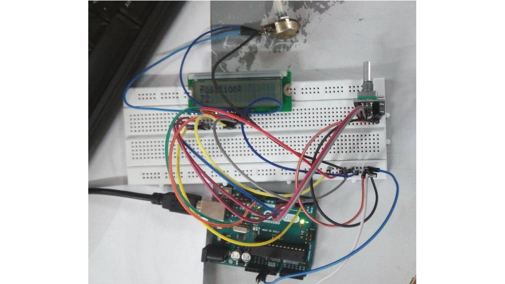
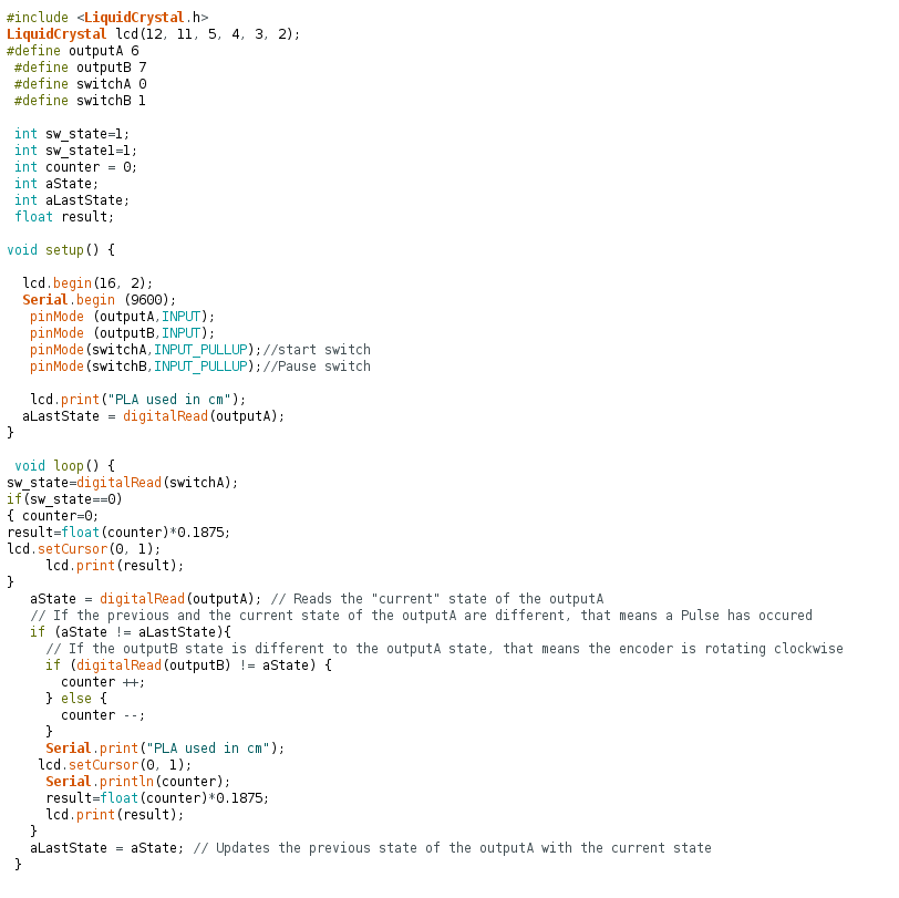
Intially I used the arduino board in the lab for testing the operation of the rotary encoder . The arduino code used for testing my intial setup is given below

The arduino code for the intial testing is provided here
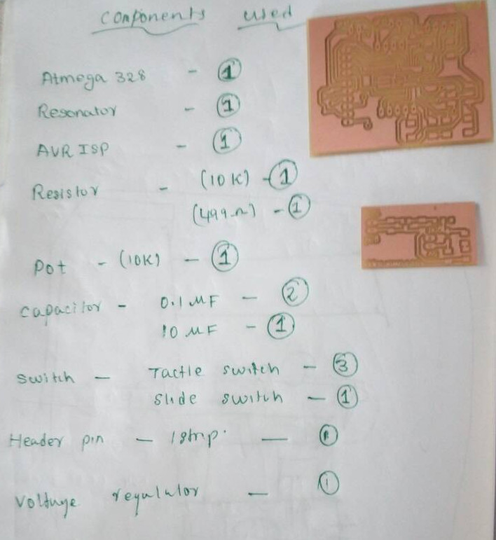
BILL OF MATERIALS USED
| Sl.No | materials | quantity | cost in rupees |
|---|---|---|---|
| 1 | Rotary encoder | 1 | 150 |
| 2 | atmega 328 | 1 | 130 |
| 3 | LCD display | 1 | 440 |
| 4 | resonator | 1 | 60 |
| 5 | 10 k potentiometer | 1 | 10 |
| 6 | Capacitor | 3 | 2 |
| 7 | voltage regulator | 1 | 20 |
| 8 | Tactile switch | 1 | 65 |
| 9 | slide switch | 1 | 54 |
| 10 | Push button | 3 | 30 |
| 11 | jumper wires | 10 | 20 |
| 12 | resistor | 3 | 36 |
| 13 | 9v battery | 2 | 40 |
| 13 | battery clip | 1 | 10 |
| 14 | header pins | 1 strip male and 1 strip female | 30 |
| Total | 1100 |
Therefore I spend 18 US dollers for making my U-FMI in FABLAB.
Working of Rotary Encoder
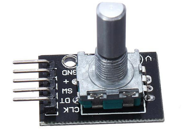
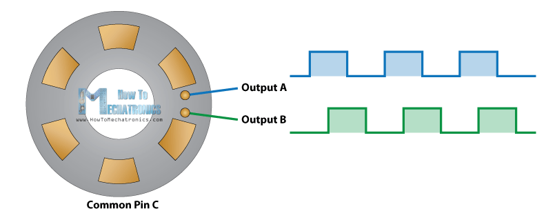
A rotary encoder is actually a position sensor which determine the angular position of a rotating shaft. The encoder contains a disk inside ,which has evenly spaced contact zones that are connected to the common pin C and two other separate contact pins A and B.
|
|
|---|
During the rotation of disc ,actually what happens is ,the pins A and B will start making contact with the common pin creating two square wave output signals with phase difference of 90 degree. During clockwise rotation output A will be ahead of output B.

The encoder position is determined by the number of low to high transition of signal from either pinA or pinB .The rotation direction can be obtained from the phase difference.For more details click here
PCB designing and Digital Fabrication
ATMEGA328 BOARD
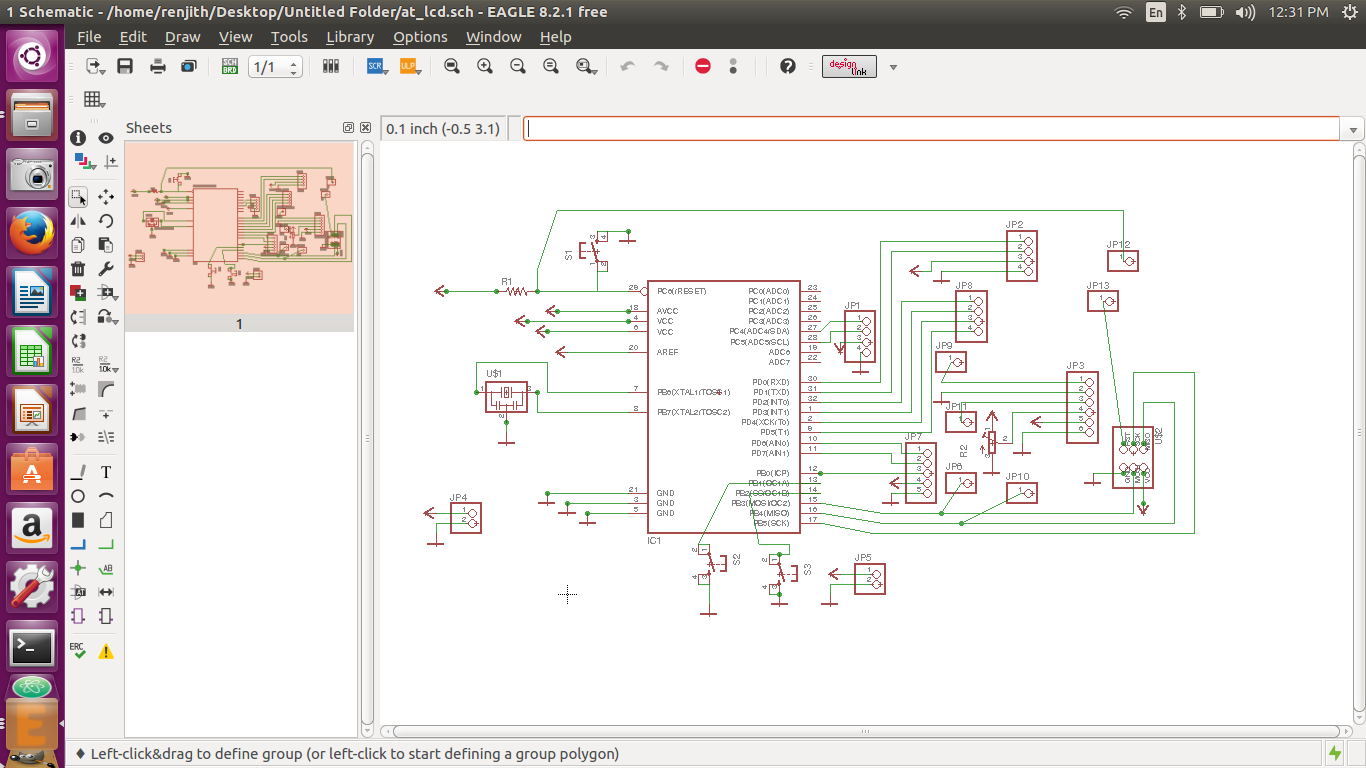
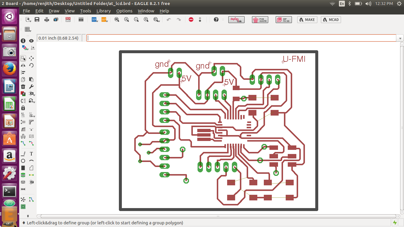
I use EAGLE to design my board.The schematic of my atmega 328 board and board image is given below
|
|
|---|
Even though I am an electronics engineer,I was not able or it is better to say I did not tried manual routing.Finally I decided not to autoroute. But the process was tough for me ,I tried a lot and it took 3 days to finish my routing.It was a great experiance and I felt very happy.The process of manual routing enhanced my self confidence.
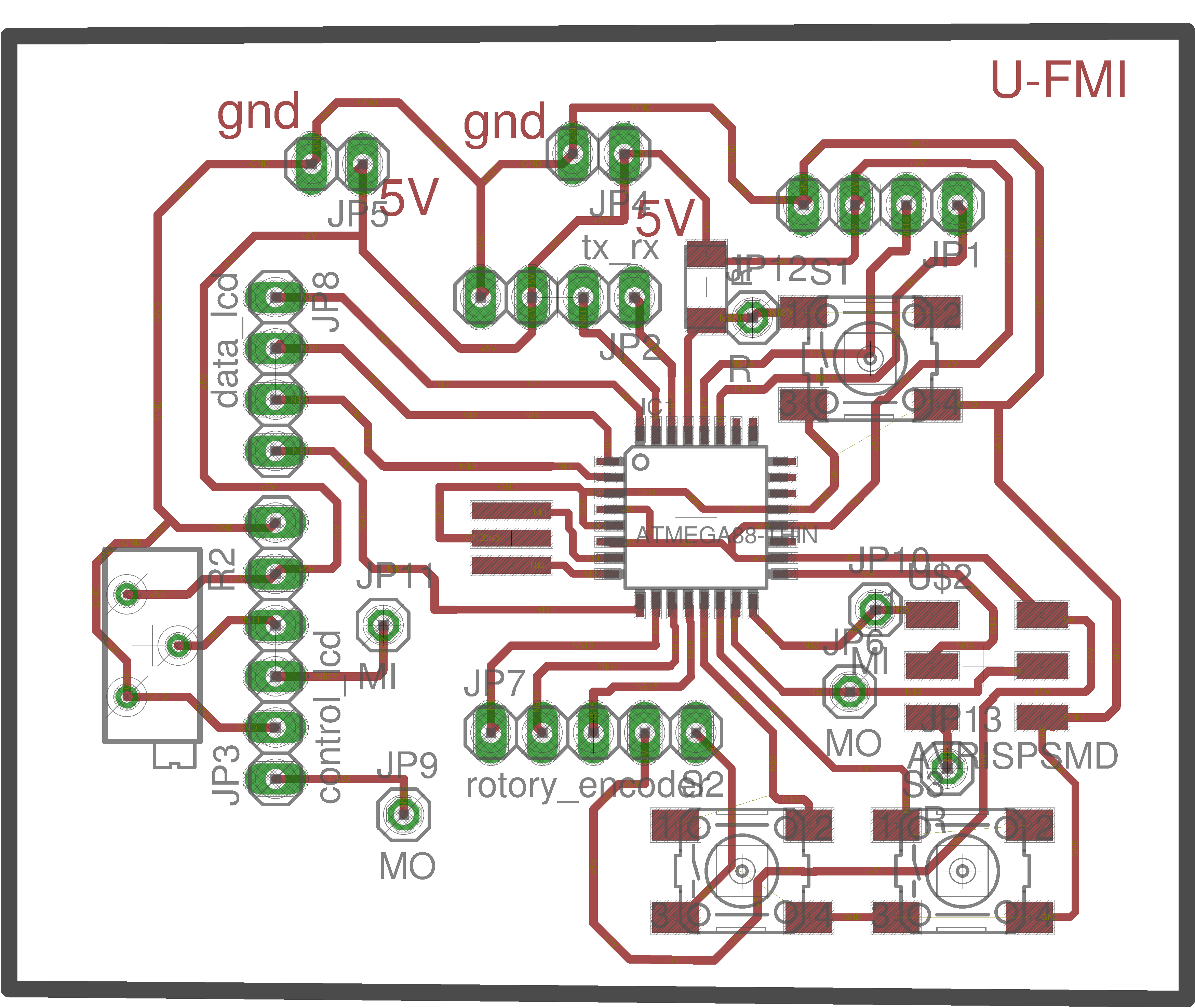
The final pcb image is given below.which is further used for milling and cutting after layer selection in eagle.
|
|
|
|---|
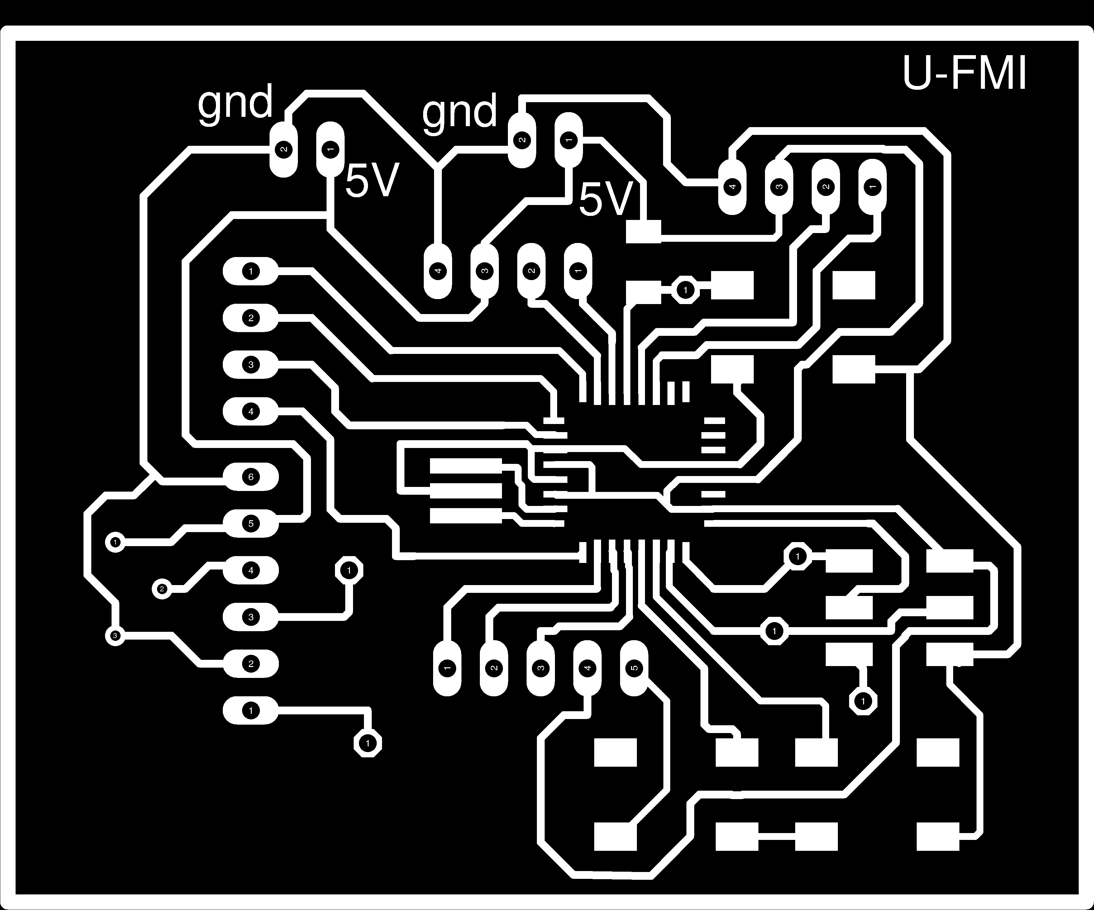
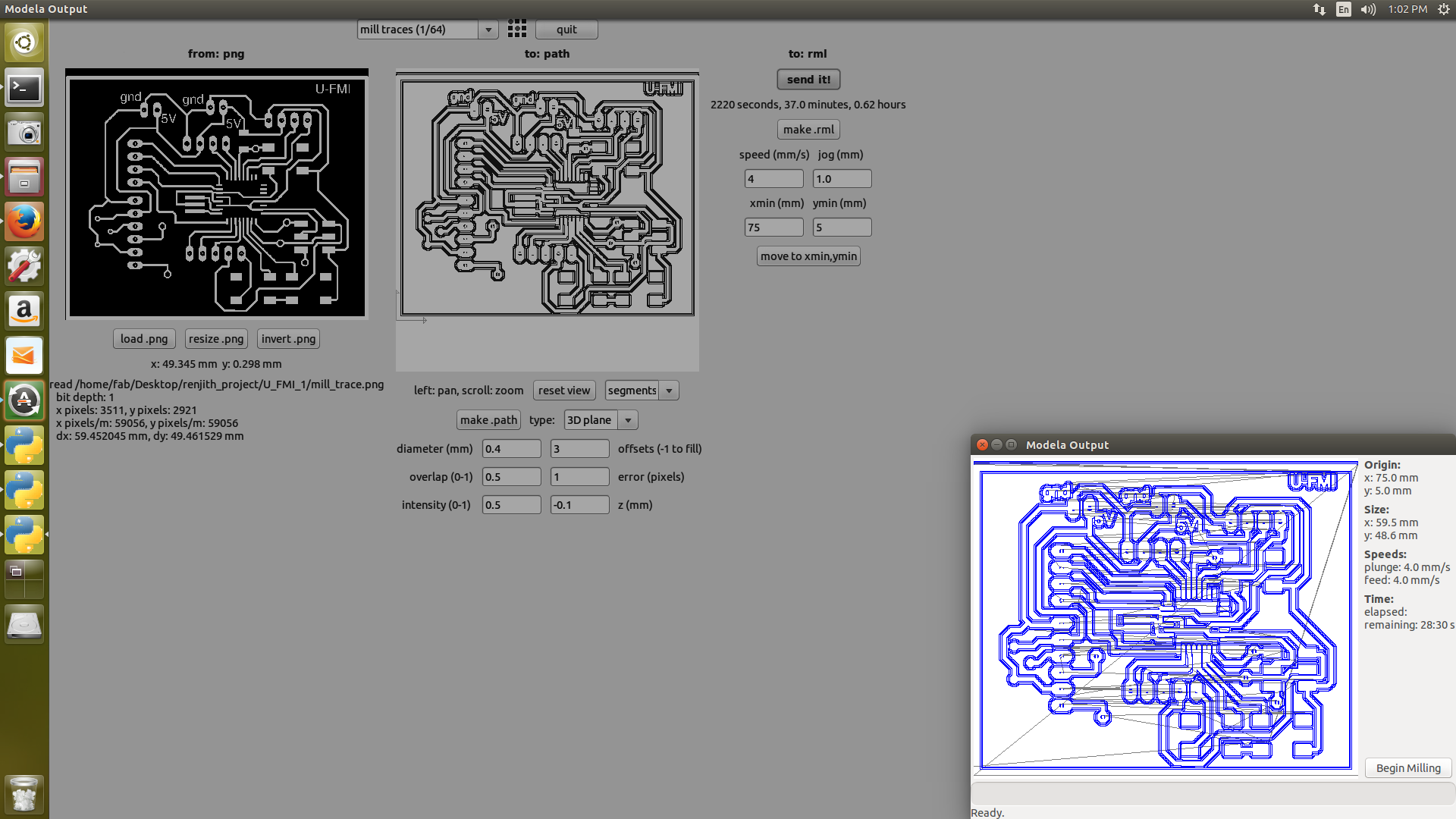
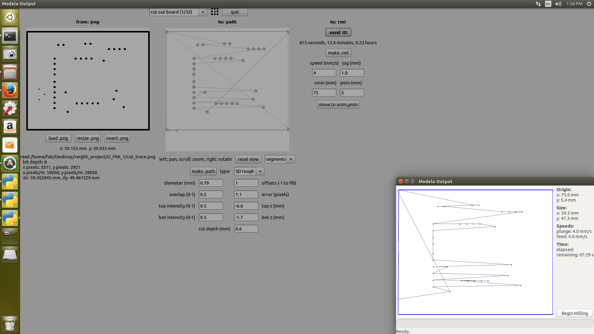
The trace width was adjusted in such a way that I used 14 mil near to the atmega328 IC and change to 16 mill when not near to the IC. The mill trace , cut trace for my pcb is given above with the final pcb image.
|
|
|
|---|
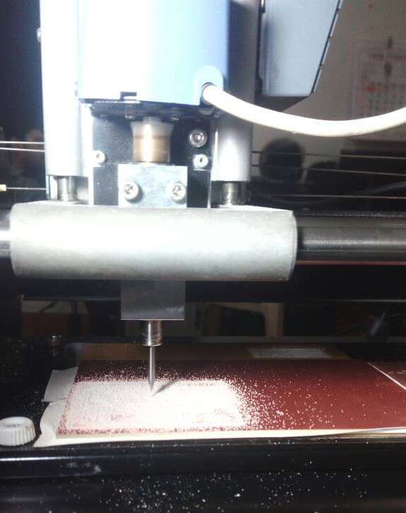
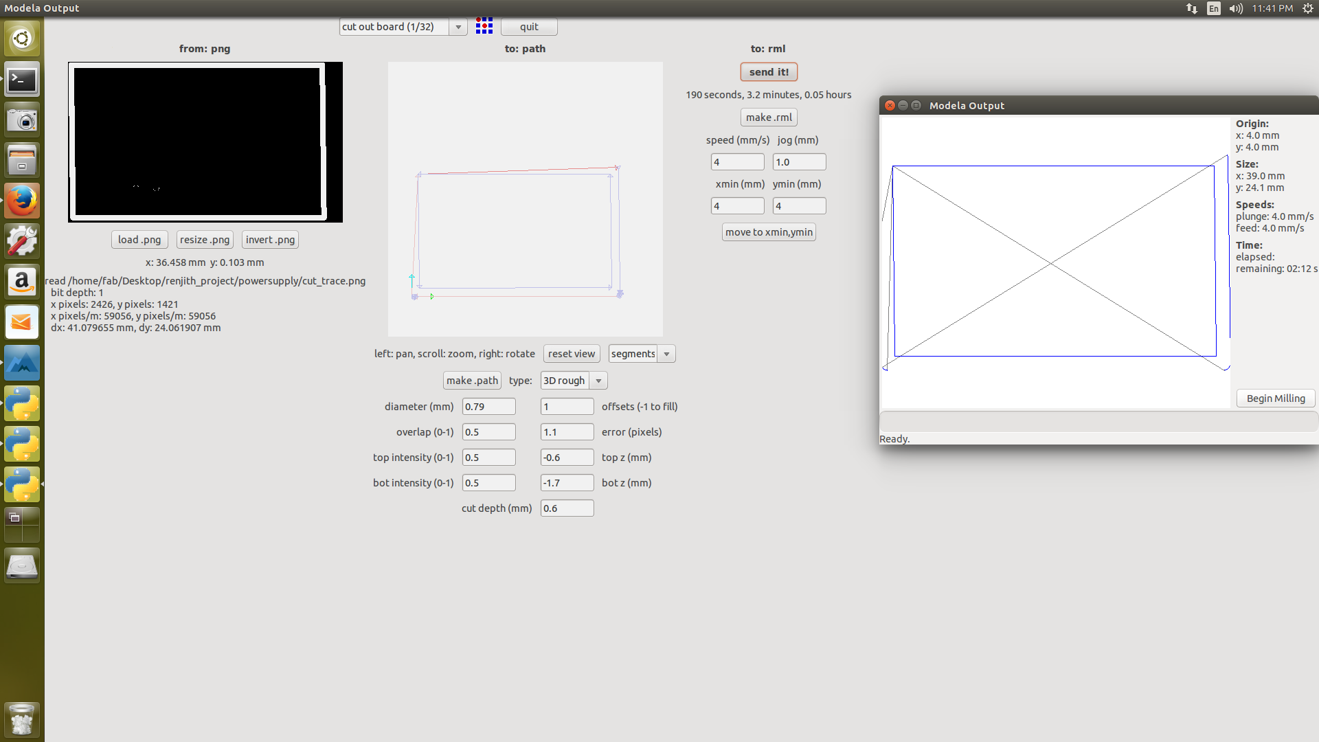
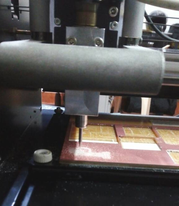
The screen shots for the milling and cutting process along with pcb milling in the modella machine is provided above
POWER SUPPLY BOARD
While manual routing of my pcb ,It was difficult for me to do the routing when the power supply was also included so I thought of spliting them,I think that was a good option for dealing with complex circuits .Finally my power supply board is manually routed
|
|
|
|---|
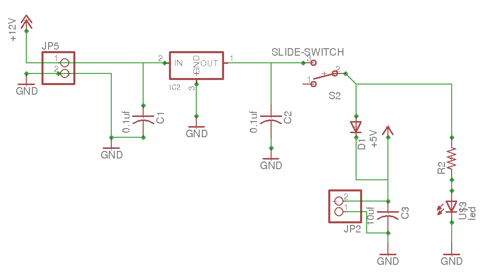
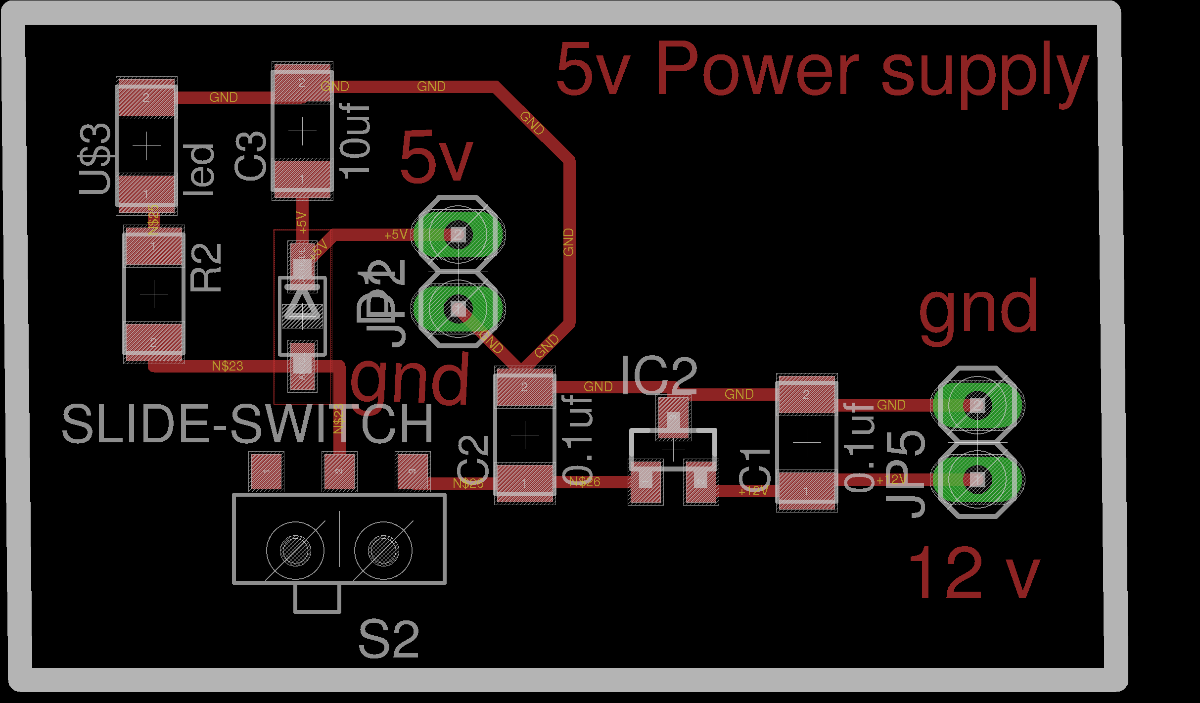
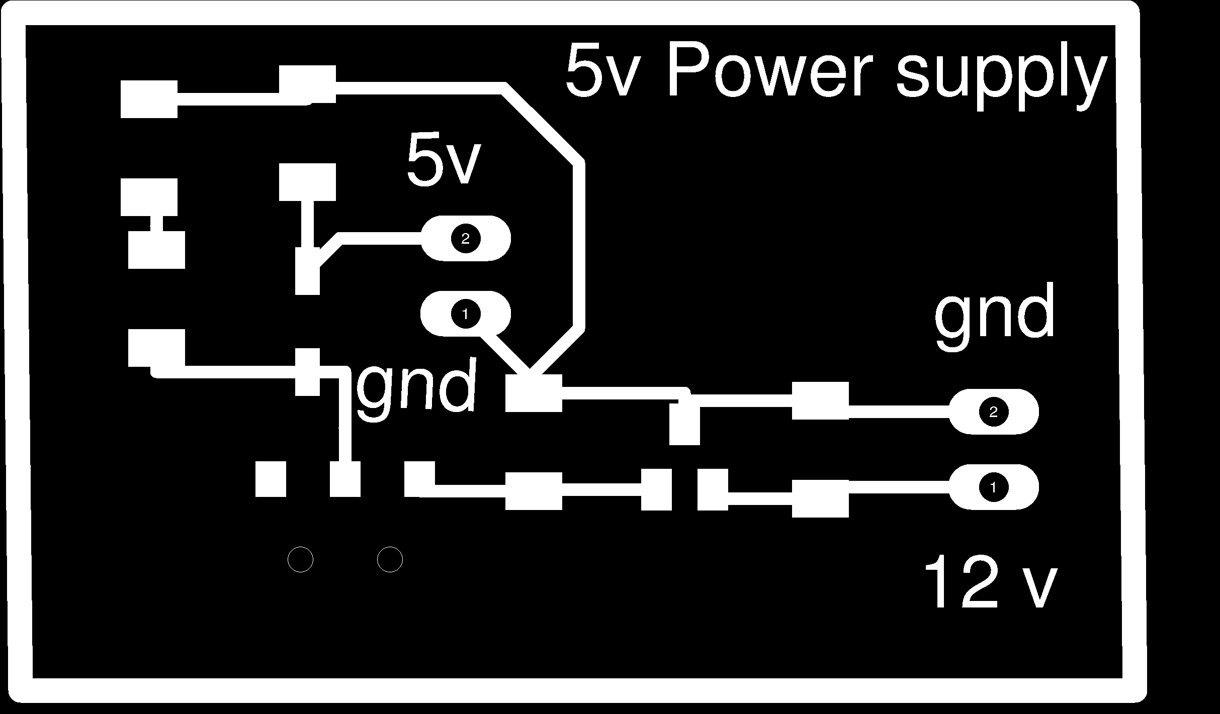
The schematic ,board and final pcb image of my power supply is shown above.It was a better option for using the seperate power supply board. I placed the power supply board underneath the atmega328 board .The spliting helped me while making the final product.If the pcb was not splited the horizontal space needed more compared to the case when it is splited. There was another option of double sided pcb,but I am not confident enough to make double sided pcb now, because I losed almost 3 days for routing itself.Next time when I am going for Prototype ,doublesided pcb will be opted.
|
|
|
|---|
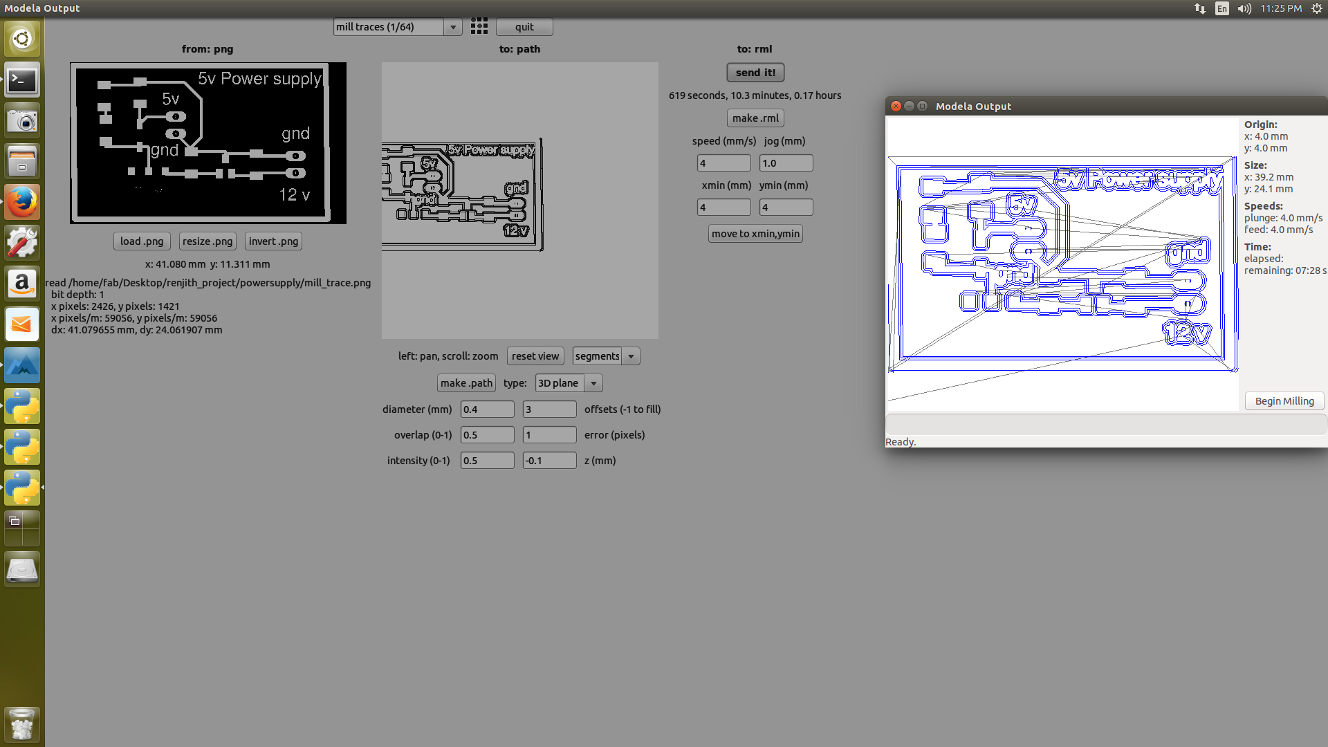
The screen shots for the milling and cutting process along with pcb milling of power supply board in the modella machine is provided above.
|
|
|
|---|
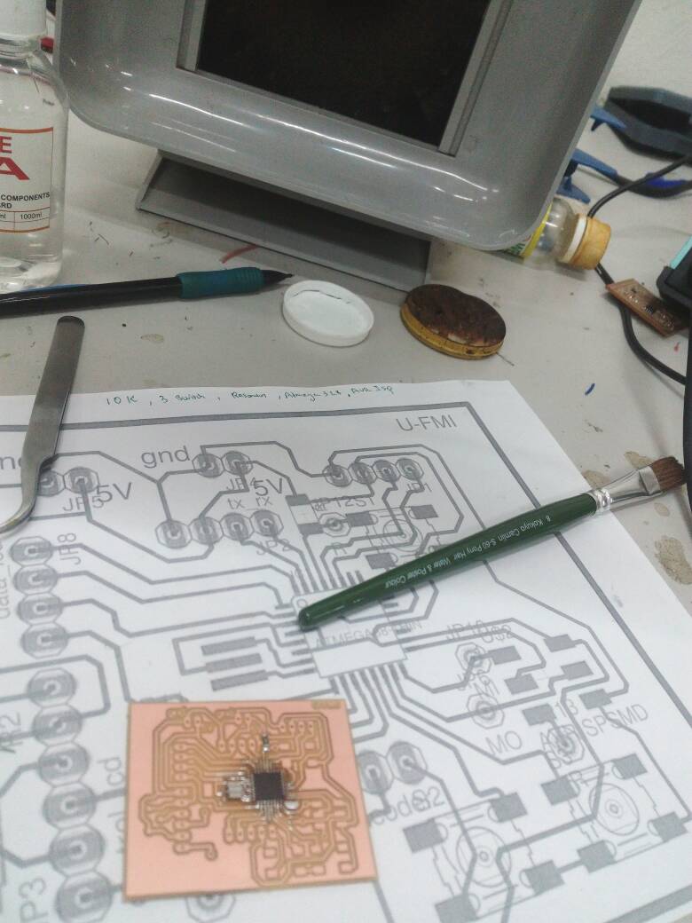
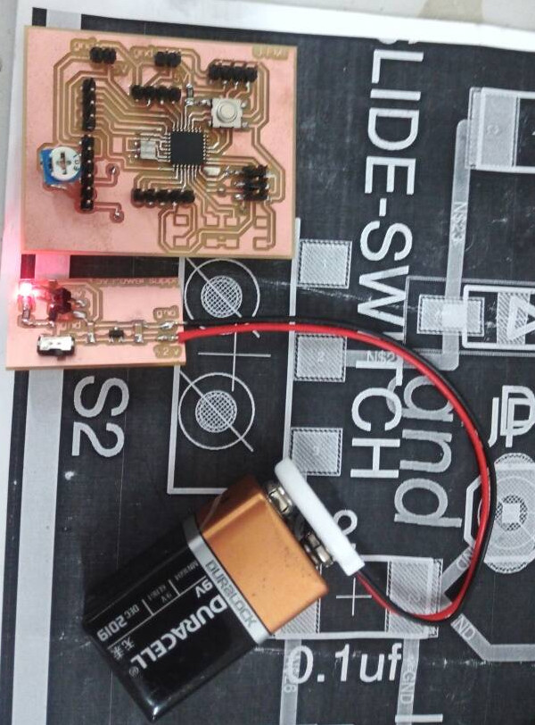
This time also soldering was tough ,I strugled to place the IC at correct position and solder it ,finally some how I finished the task of soldering. I like soldering because it is very difficult for me to deal with soldering.
The board , schematic ,mill trace and cut trace of both boards are provided here
COMPUTER AIDED DESIGN and 3D PRINTING of the CASE
Next step involved in my prototype is to design a case for U-FMI which is having the enough space to accommodate ATMEGA328 board, powersupply board,battery.In addition it should have the provision for placing LCD display,3 push buttons and finally a small oppening is required for connecting with the rotary encoder which has to be placed outside the case.
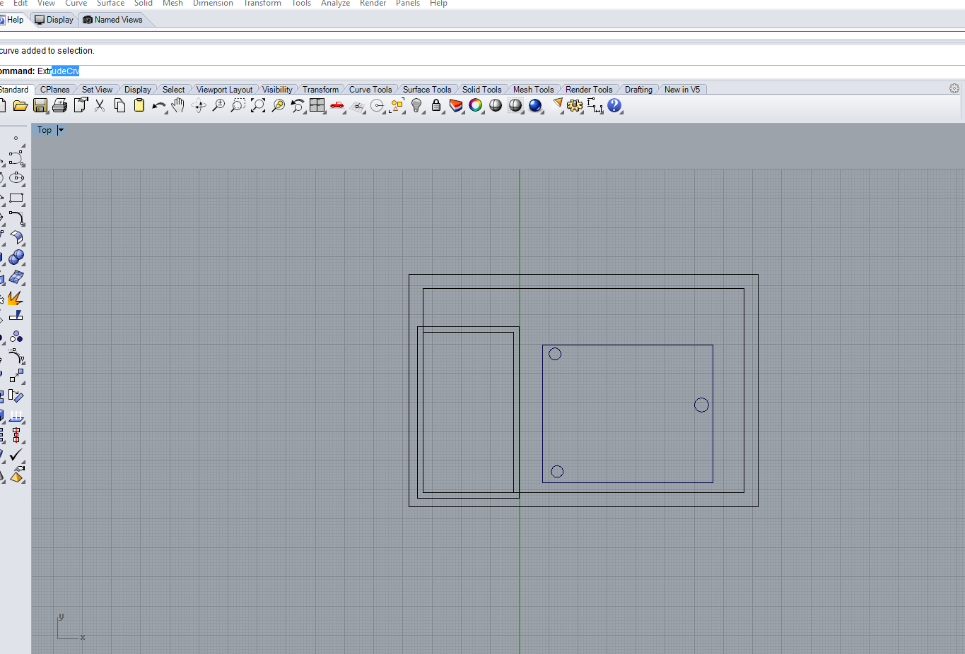
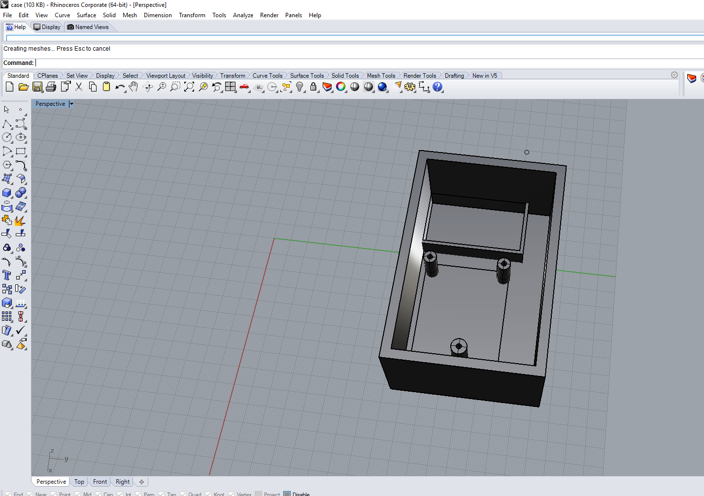
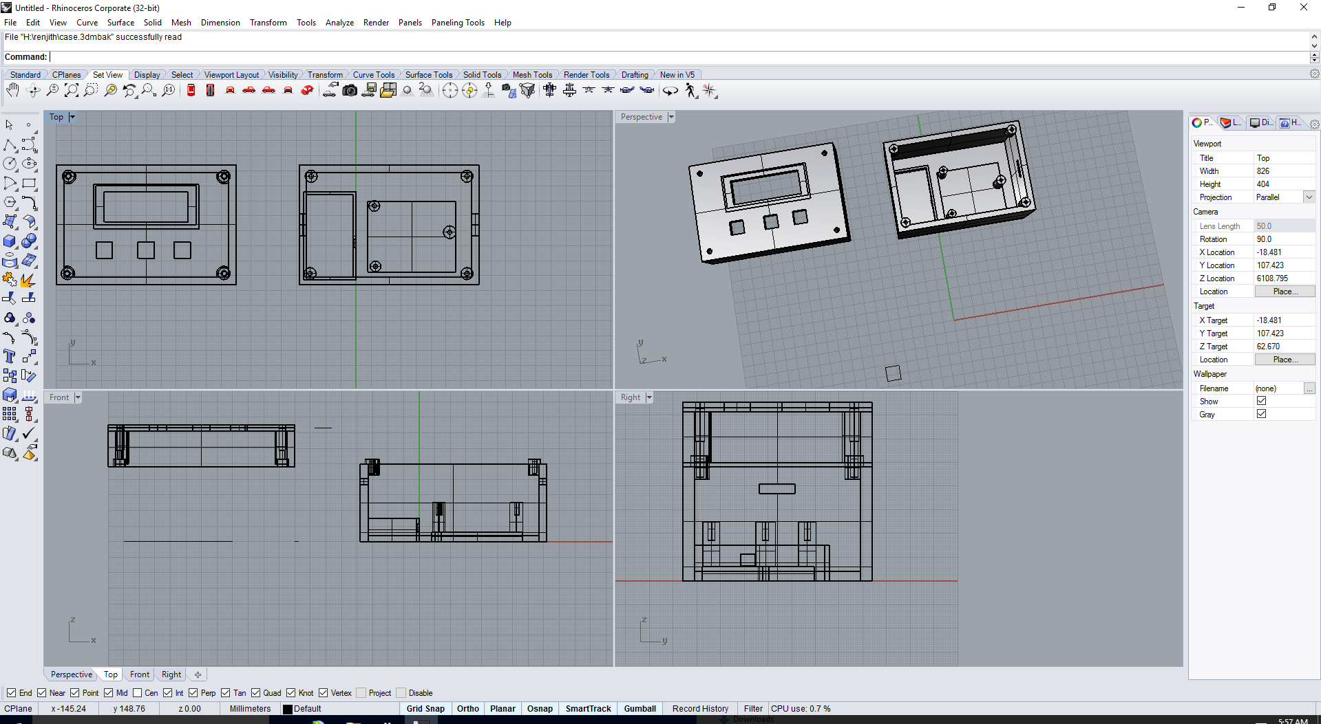
I designed my case in RHINO ,The screenshots for my case is given below
|
|
|---|
The screen shots for top view and perspective view of my bottom part of my case is shown above.From the sreen shots it is clear that, there is a provision for placing the ATMEGA 328 board and battery.The dimensions of the atmega328 board has to be obtained from the board which has been previously designed and fabricated.I have provided 3 pillers in my design which have the capability of holding the pcb and a provision is provided to screw the pcb board to the case.
|
|
|---|
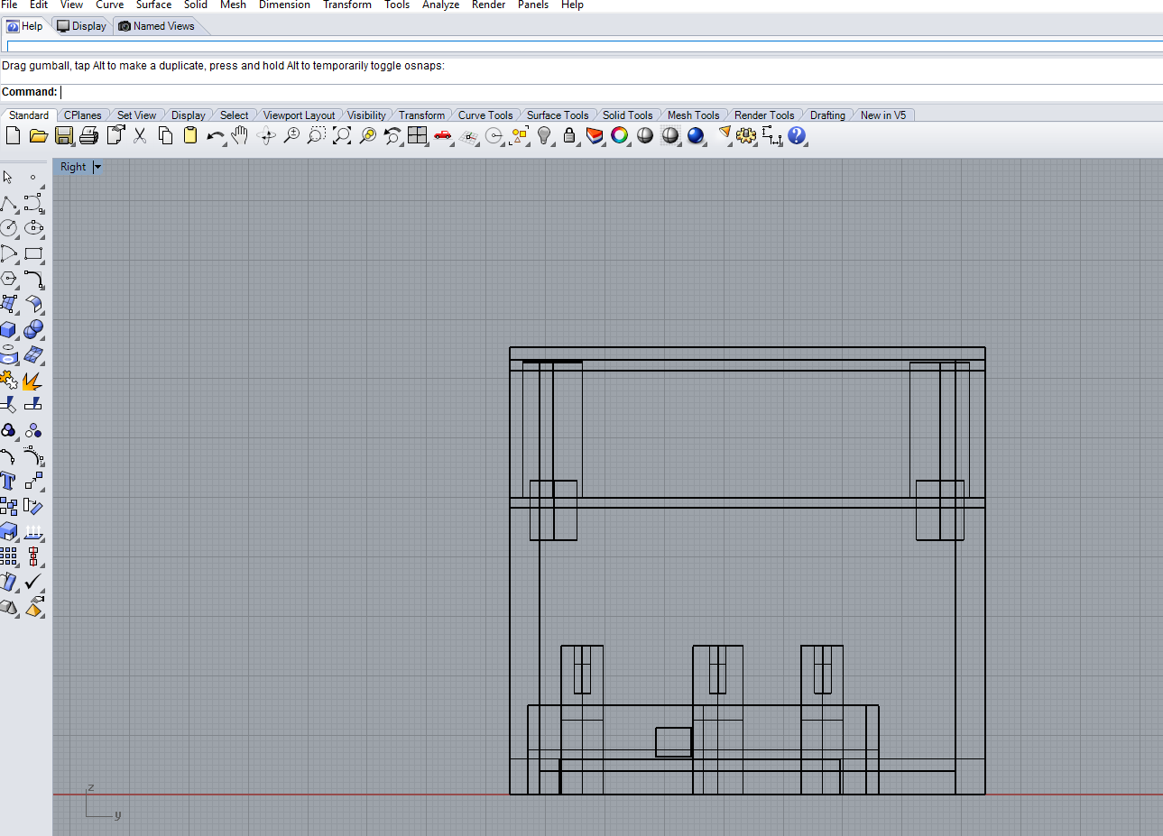
Atlast my design has been completed .The screen shots for the top view and the combined view is provided above.
|
|
|---|
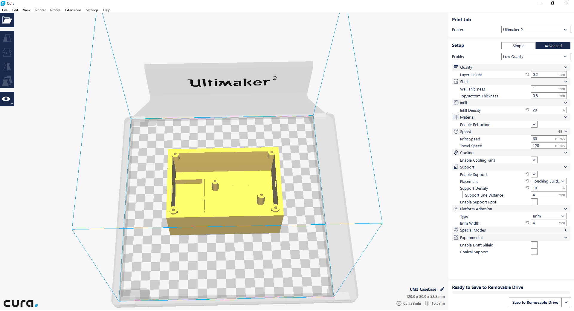
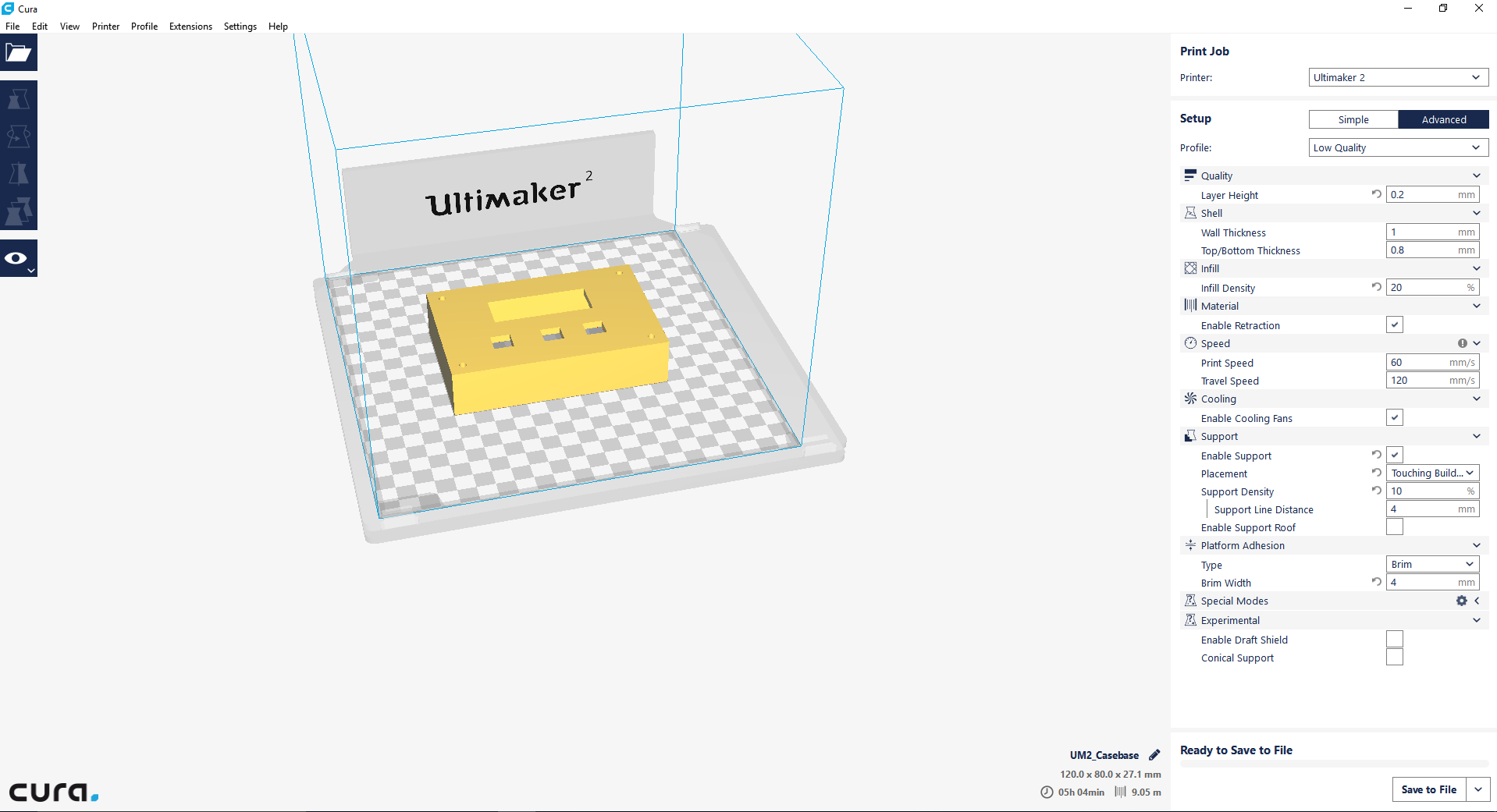
finaly my 3dm files in rhyno has been exported as STL file and opened in cura and is then converted to Gcode and opened in 3d printer using sd card and printed.The screenshots in cura is provided above,from that it is clear that 3D printing task needs almost 11 hours.
|
|
|---|
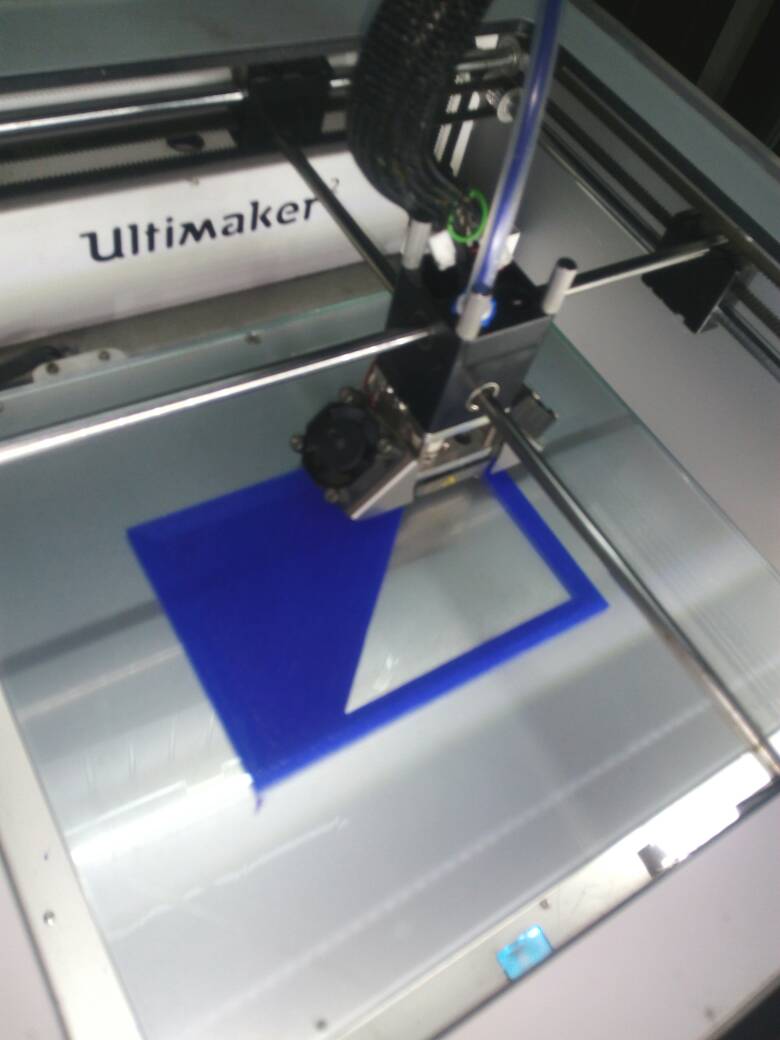
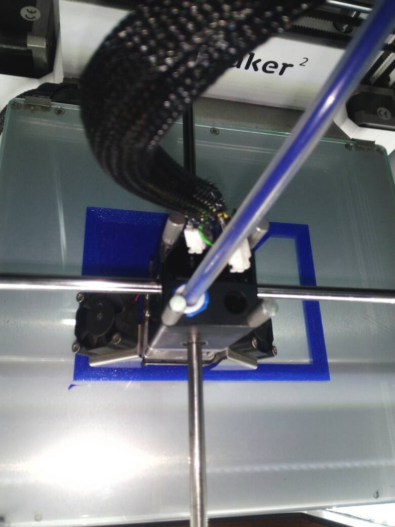
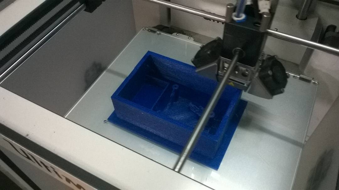
The 3d printing started .The photos show the bottom part printing process.
|
|
|
|---|
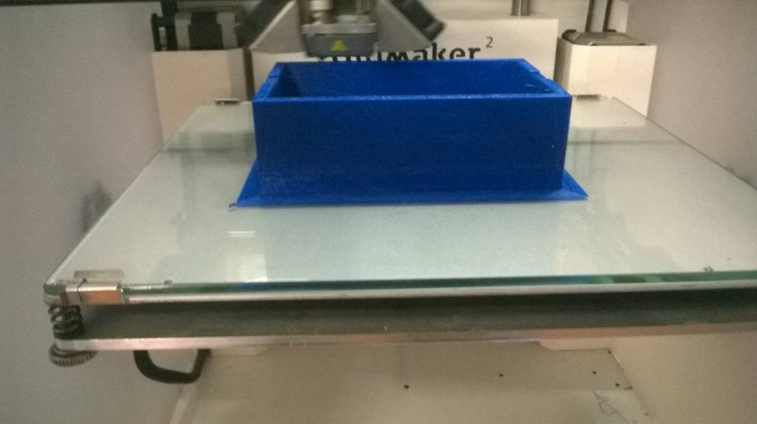
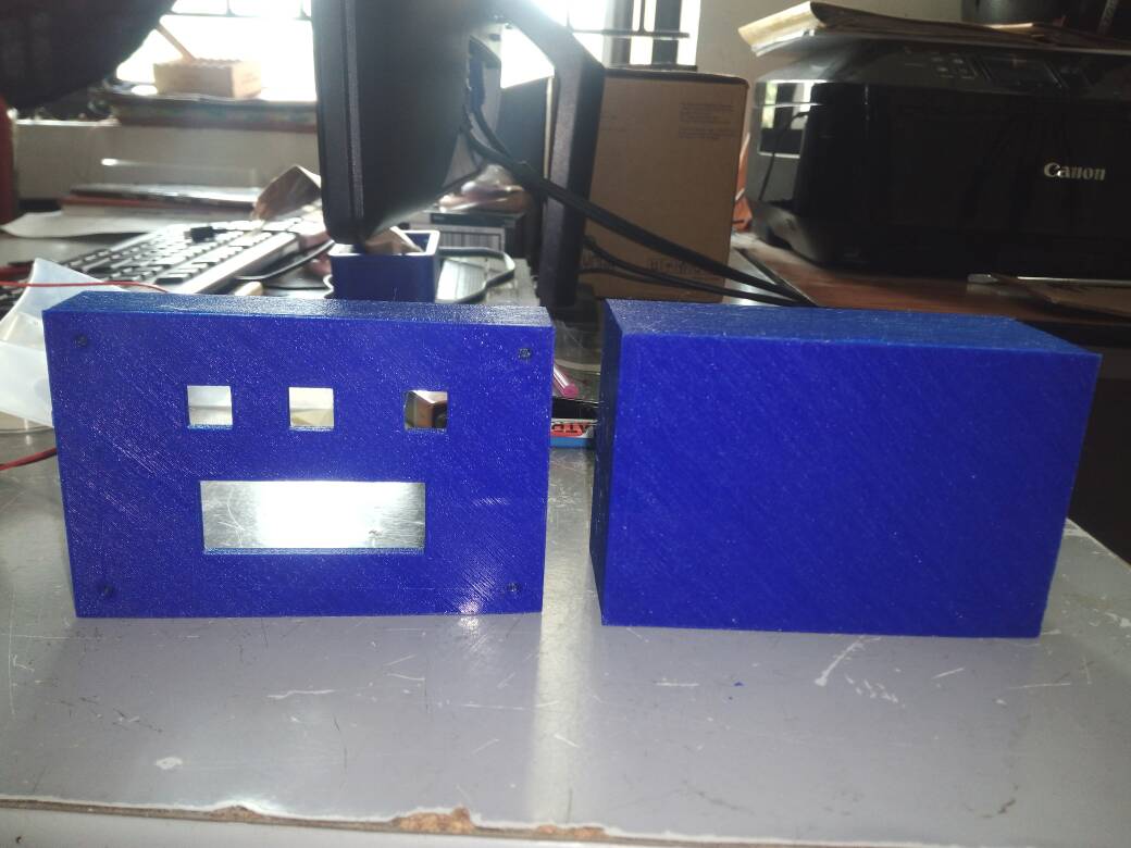
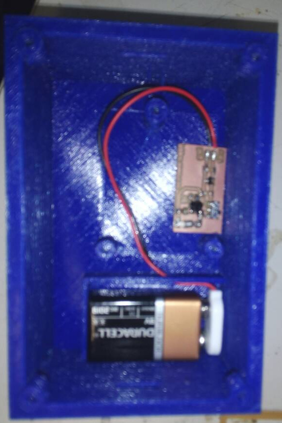
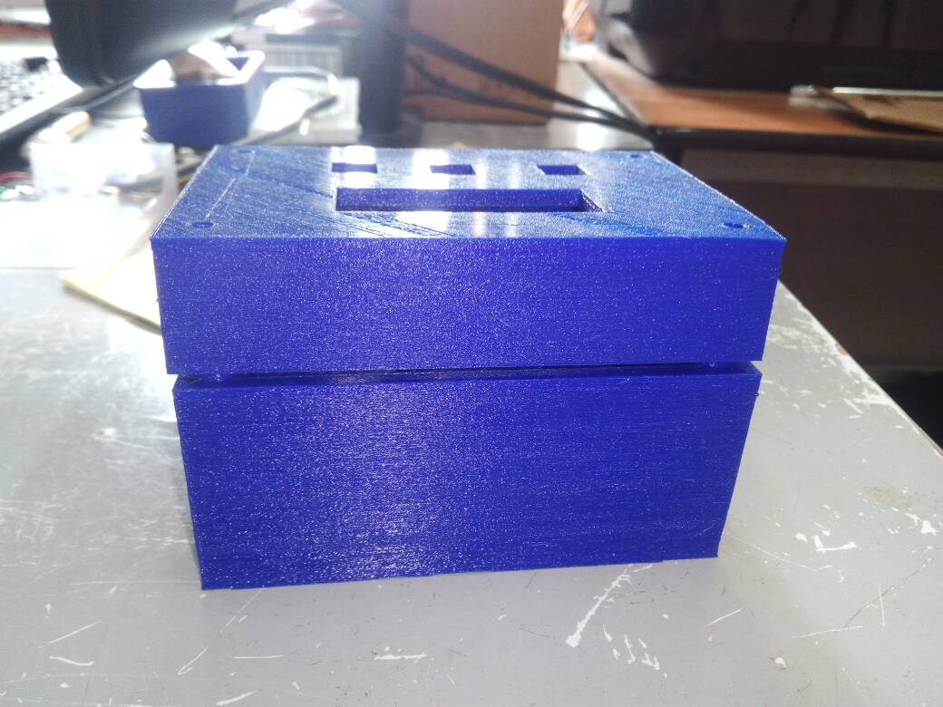
Atlast 3d printed case is ready,and it is now time to place the pcb,power supply board,battery and check whether my design is apt or not
|
|
|
|---|
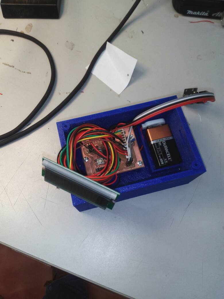
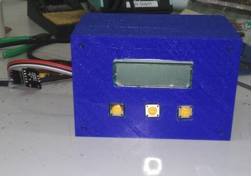
I fixed all the components in to the case.The buttons and LCD display not perfectly placed,so I done some filing with Hand files available in FABLAB and some mistakes happend because of my impatience.I managed to fix the LCD and buttons by using glue gun.
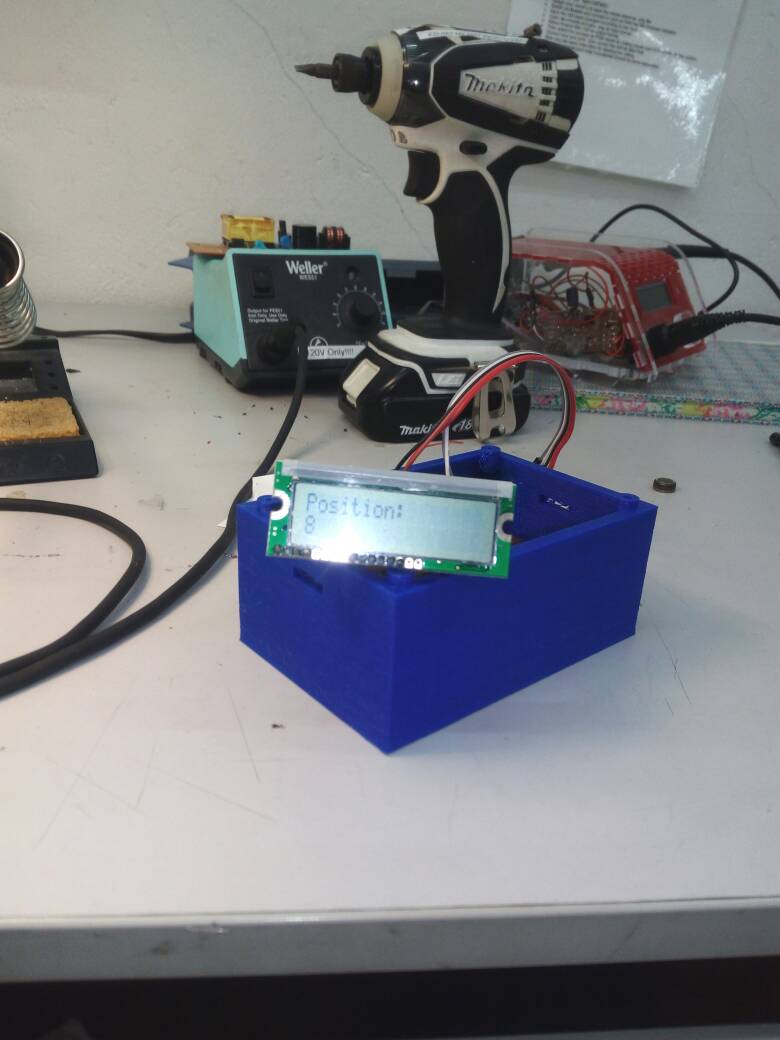
I programmed my atmega 328 board with the same arduino code which was used previously.I was happy that it worked as expected
|
|
|---|
The rhino file and stl files for my designs are provided here
LASER CUTTING OF GEAR SYSTEM
For measuring the length of the PLA used for 3D-printing using rotary encoder needs a pulley so that the moving PLA can be able to rotate the shaft of rotary encoder.while designing I first thought of fixing a bearing in such a way that PLA will be moving between the bearing and the shaft with a gear.The bearing avialable in the lab is having
inner diameter = 8 mm
outer diameter = 22 mm
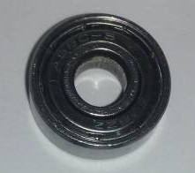
I decided to make a rectangular base with bearing fixed at one position and rotary encoder shaft fixed in such a way that the PLA of diameter 2.85 mm slides between the gear fixed to the shaft of rotary encoder and the bearing.
GEAR for the shaft is designed in Inkscape.The screen shots below shows the procedure used for creating the gear.
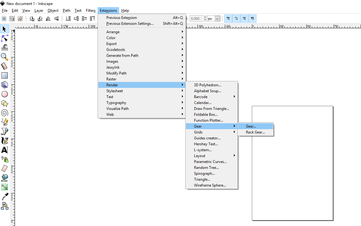
In order to make a gear in Inkscape we have to go to the extensions -> Render ->Gear in the main window
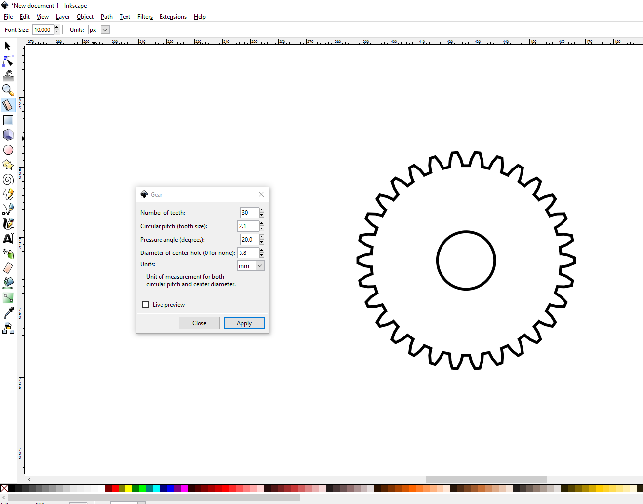
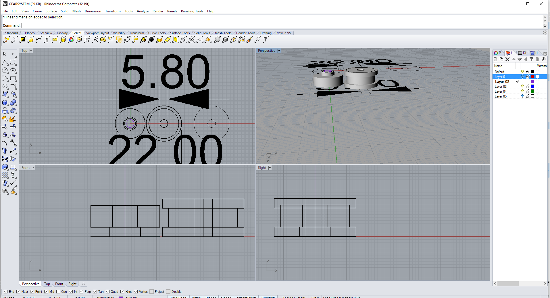
By trial and error method I fixed no of teeth =30, circular pitch =2.1 and pressure angle =20.0.Diameter of center hole is made equal to 5.8 mm ,since the rotary encoder shaft region where I was supposed to fix the gear is of diameter 5.8 mm.
The svg file for the gear is given here
While designing to put a hole of 6.62 mm diameter ,which is used to fix the rotary encoder to the rectangular plate.In order to fix the bearing I designed a circular disc of acrylic in such a way that it should be able to fix the bearing to the rectangular plate .I tried with a circular disc of 8 mm diameter for that ,but it is not tight enough to hold the bearing to the rectangular plate.so I increased the diameter to 8.1 mm,8.2 mm,8.3 mm and 8.4 mm .The circular disc of 8.4 mm when placed inside the hollow region of bearing fitted nicely.
The screen shots of my designing process is provided below.
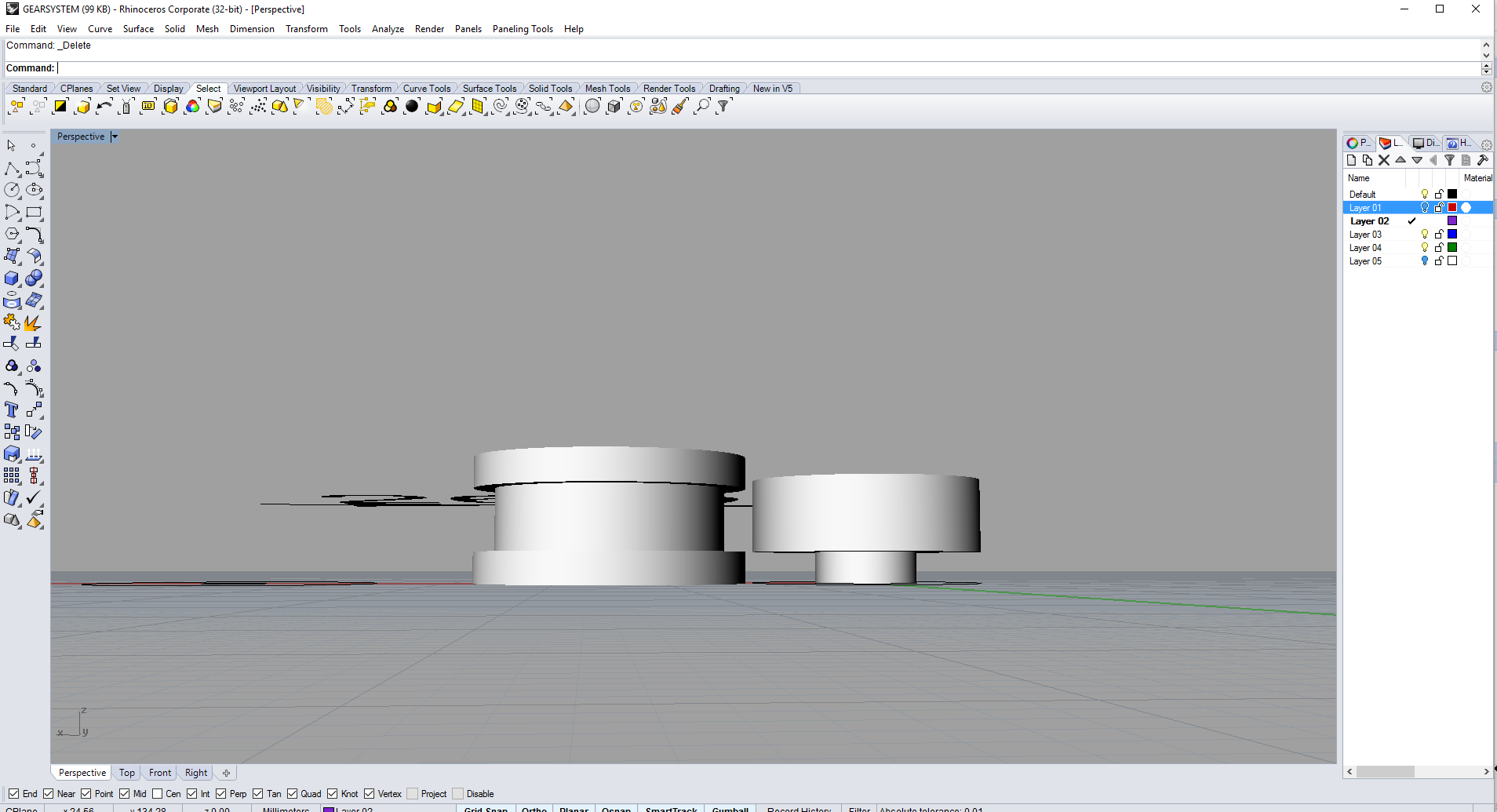
Persepctive veiw of my design is shown above.It includes a 3d model of the bearing in order to have an idea of dimensions required for the rectangular plate.
Gear used should be fixed to the shaft of the rotary encoder in such a way that it should be sandwitched between two circular shells of inner diameter of 5.8 mm and outer diameter of 22 mm.I selected 22 mm to have a similarity with the bearing and the inner 5.8 mm is required because it is the diameter of the shaft of the rotary encoder used.
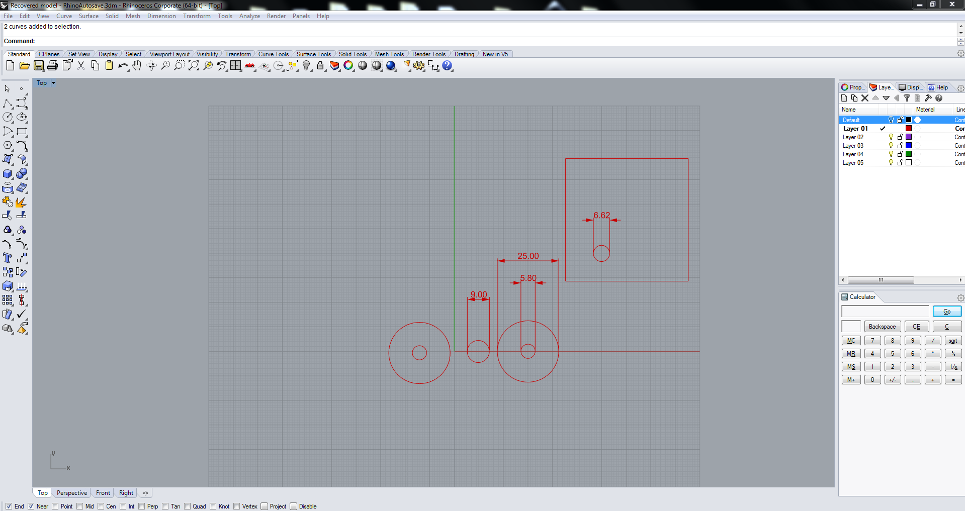
But finally considering the diameter of 2.85 mm PLA ,I changed the outer diameter of circular shell to 25 mm from 22 mm.A circular disc of diameter 9mm and height of 3mm ie provided by thickness of the acrylic sheet is being designed to hold the bearing in such a way that it will be above the ground level by 3mm.Finally the dimensions of the the rectangular plate is decided to be having a length of 60 mm and bredth of 60 mm,considering the factors such as it has to acomodate both the gear system and the bearing.
After that I exported the 2d of my design in rhyno in dxf format and opened in inkscape,Further laser printed the required components.
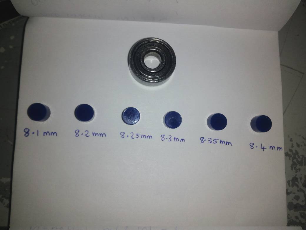
The above figure shows the Iterations I have done for finding the diameter of the circular disk which is apt for the bearing ,such that it will be a tight fit. Finally I confirmed circular disc of 8.4 mm diameter to a perfect fit for my bearing.
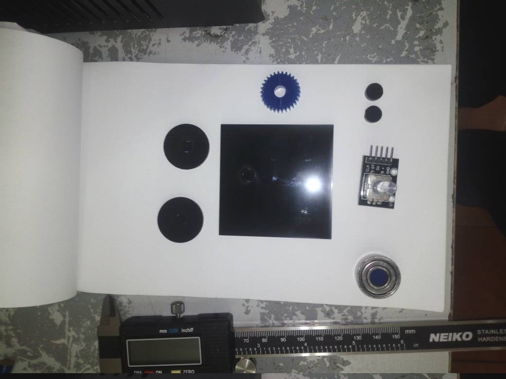
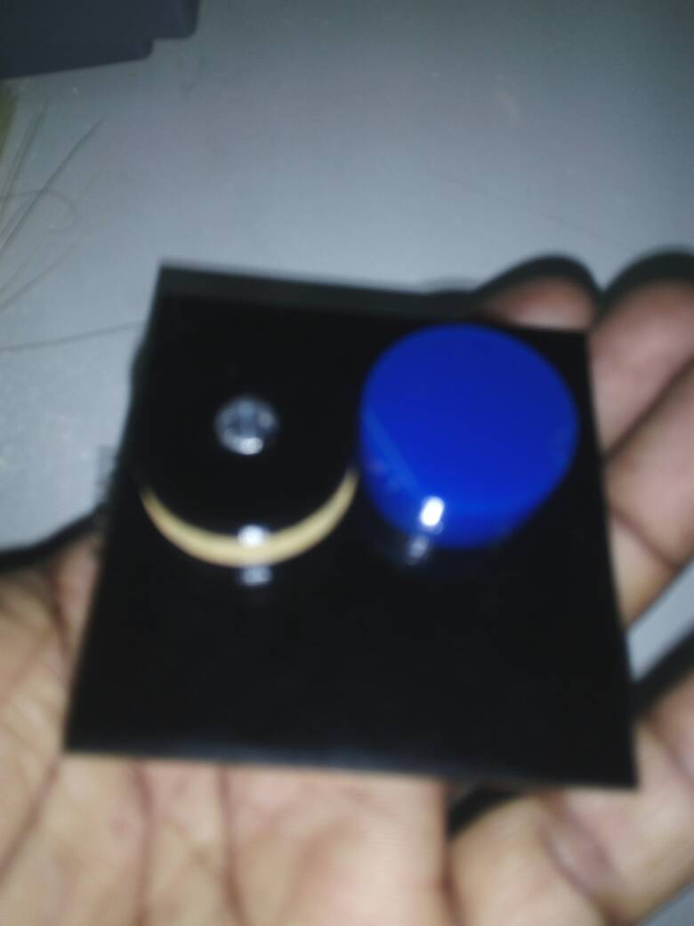
After a few hours of research I completed the laser printing of the required stuff for gear system .The above figure shows the laser printed parts of the gear system along with the bearing and rotary encoder.
|
|
|---|
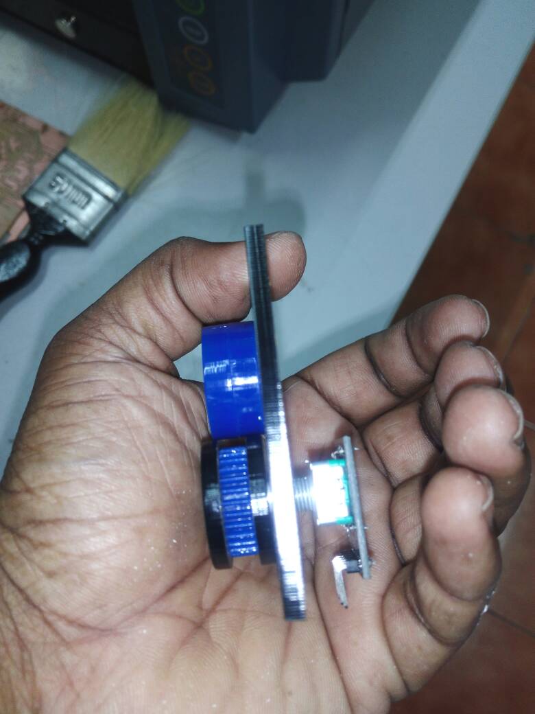
First we have to fix the rotary encoder via the hole of 6.62 mm to the rectangular plate,after that fix the base circular shell followed by the gear and finally place the another circular shell through the shaft of rotary encoder.
The sandwitch should be tightly fixed so that ther is no gap between them.Then it is the time to decide where to fix the bearing ,for that I just placed the bearing in such a way that it is exactly placed 2.85 mm from the sandwitched gear.Gear is having a diameter of almost 22 mm and the circular shell is having an outer diameter of 25 mm,so there itself we are having a clearence of (25-22)/2 ie 1.5 mm.Therfore extra 2.85mm -1.5 mm =1.35mm is required.
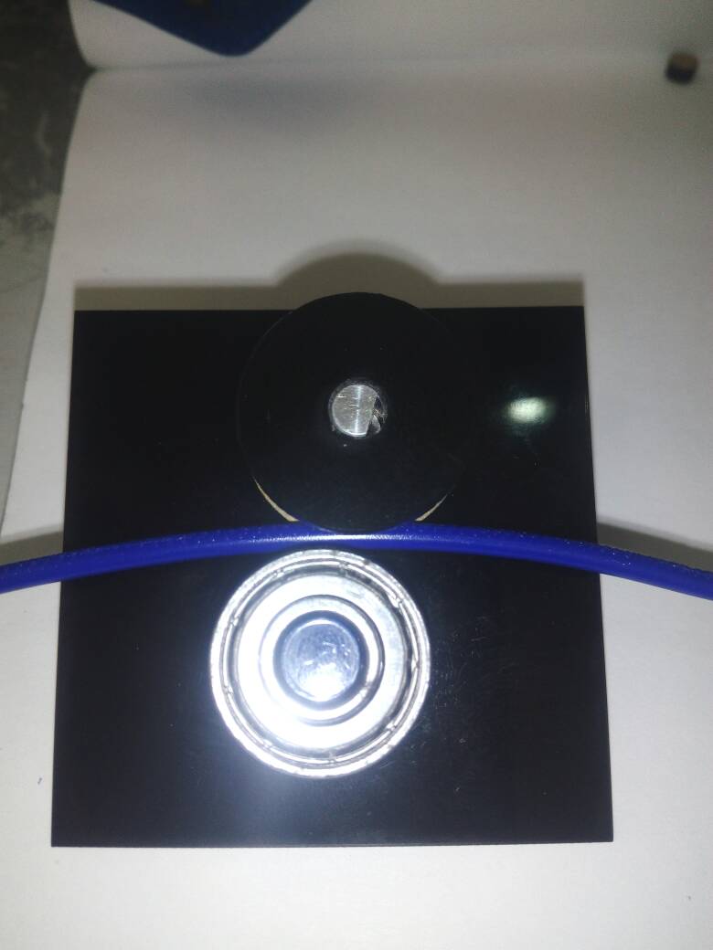
I placed the bearing using a double sided tap,but It seemed to be a bad idea of using bearing ,because when the PLA is moving it is not rotating the gear ,instead it rotates the bearing.I changed my idea ,instead of bearing I placed 3 circular disc of diameter 22 mm with a height of 3mm one above the other to mave a circular disc of 9mm height.I used chloroform available in the lab for sandwitching this circular disc,and finally fixed to the rectangular plate ,considering the gap requirement.

|
|
|---|
We should be careful while handling chloroform.I covered my face with a wet cloth to avoid inhaling of chloroform.Using syringe I took few drops of chloroform from the bottle containing chloroform.I used chloroform for sticking together the circular disc used instead of bearing,which is further fixed to the rectangular base.
|
|
|---|
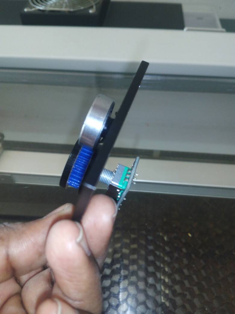
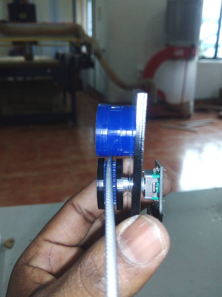
Finally my gear system is ready,I pulled a small strip of PLA placed in between the gear fixed to the shaft and the fixed circular disc , for checking whether it is possible to rotate the shaft of rotary encoder.When I pulled the PLA it starts rotating the shaft of the rotary encoder.
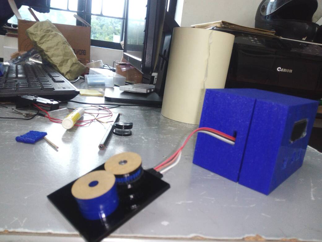
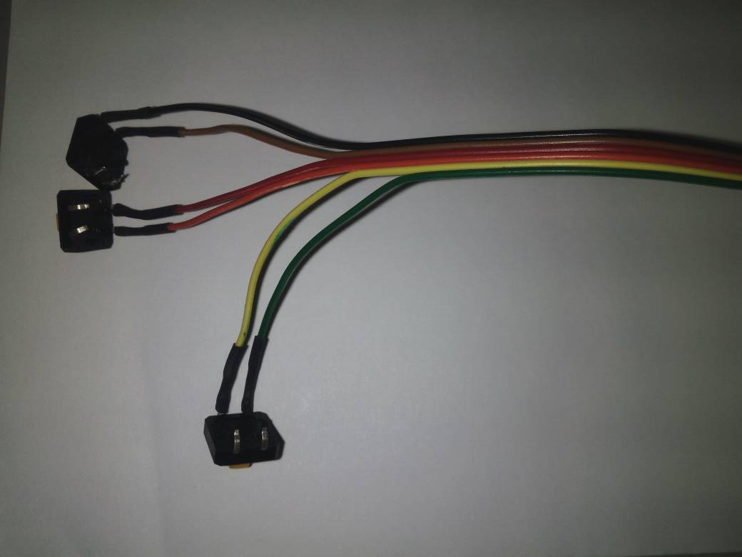
I connected the gear system to the ATMEGA 328 board using jumper wires.The above figure shows the whole system .
The rhino file and dxf files for the above designs are provided here
EMBEDDED PROGRAMMING
I edited the arduino code used intially for testing.The arduino program is given below.
Instead of using PB1 and PB2 as switch inputs, I used the tx and rx pin as input from the switch.This was actually an adjustment,since I felt difficult in soldering the input switches to the pcb after 1 week.The tx and rx pins where actually designed for serial communication ,but inorder to reduce damage to my board it was used as switch inputs.The switches where grounded at other end.
But now also there exists another issue,I didnot made any pullups for tx,rx,PB1 and PB2 .The issue is solved by activating internal pullups using the command
PinMode(SwitchA,INPUT-PULLUP);
PinMode(SwitchB,INPUT-PULLUP);
The callibration process is done using a 30 cm PLA.It was found that almost 160 counts are over when 30 cm PLA is Pulled through the gap.For counting purpose I used the program used for testing.
calculation involved in Callibration is given below,
No of count when 30 cm PLA is Pulled through the gap =160
ie 30*10^-2 meter = 160 counts
therefore 1 count = (3/1600) meter =0.001875 meter =0.1875 cm
For callibration purpose I have added an additional line in the code given by,
result=float(counter)*0.1875;
Intially inorder to assign the Digital pin mode of operation ie wether to be input or output we have to provide the statement pinMode(pin_no,mode) where pin_no is the corresponding digital pin and mode may be INPUT or OUTPUT or INPUT_PULLUP.Actually INPUT_PULLUP is used in case an internal pulup is required.SwitchA is being used for reset.
void setup() {
lcd.begin(16, 2);
Serial.begin (9600);
pinMode (outputA,INPUT);
pinMode (outputB,INPUT);
pinMode(switchA,INPUT_PULLUP);//start switch
pinMode(switchB,INPUT_PULLUP);//Pause switch
lcd.print("PLA used in cm");
aLastState = digitalRead(outputA);}
In order to reset the U-FMI I have added few lines in the code which is being given below,
sw_state=digitalRead(switchA);
if(sw_state==0)
{ counter=0;
result=float(counter)*0.1875;
lcd.setCursor(0, 1);
lcd.print(result);}
In the above code sw_state is updated with the state of digitpin switchA ,this pin is given an internal pull up ie it will be high when switch is not pressed and it will become low when we push the switch because the other end of the switch is connected to the ground.
|
|
|---|
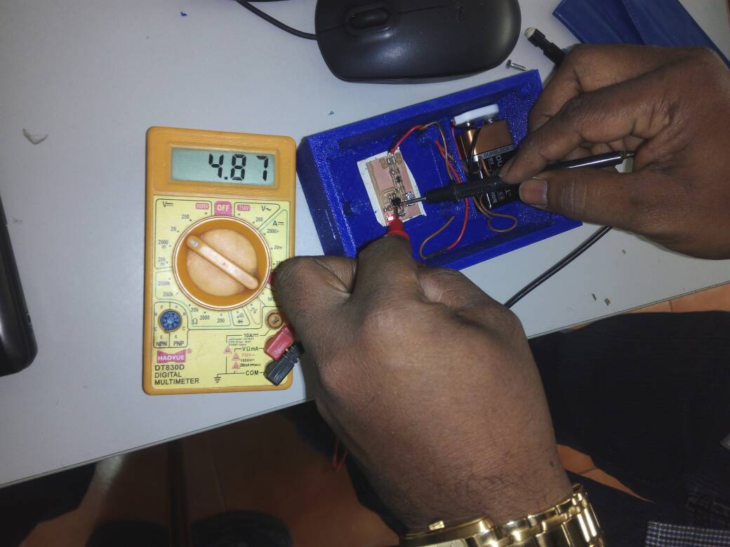
Before programming I thought of assembling the U-FMI once more,because I have to connect 2 switches to the atmega328 board ie to tx and rx pins and another switch to control the power supply from the power supply board to the atmega328 board.I replaced the battery inside the case,because the previous battery was over. Then I checked whether powersupply board is working properly.I got a voltage regulation of 4.87 volt when using a 9 v battery.
In order to fix the switches and LCD display properly I used glue gun.The above figure shows how I fixed the components to the case.
ISP programmer is used to program my board placed inside the case using arduino IDE.The program was not burning atfirst,I tried 10 to 15 times and atlast it got programmed.I dont know why this happened.
The final arduino code for the U-FMI is provided here
VINYL CUTTING OF LABELS
Inorder to make the product attractive I decided to have some labels for the switches in my project.
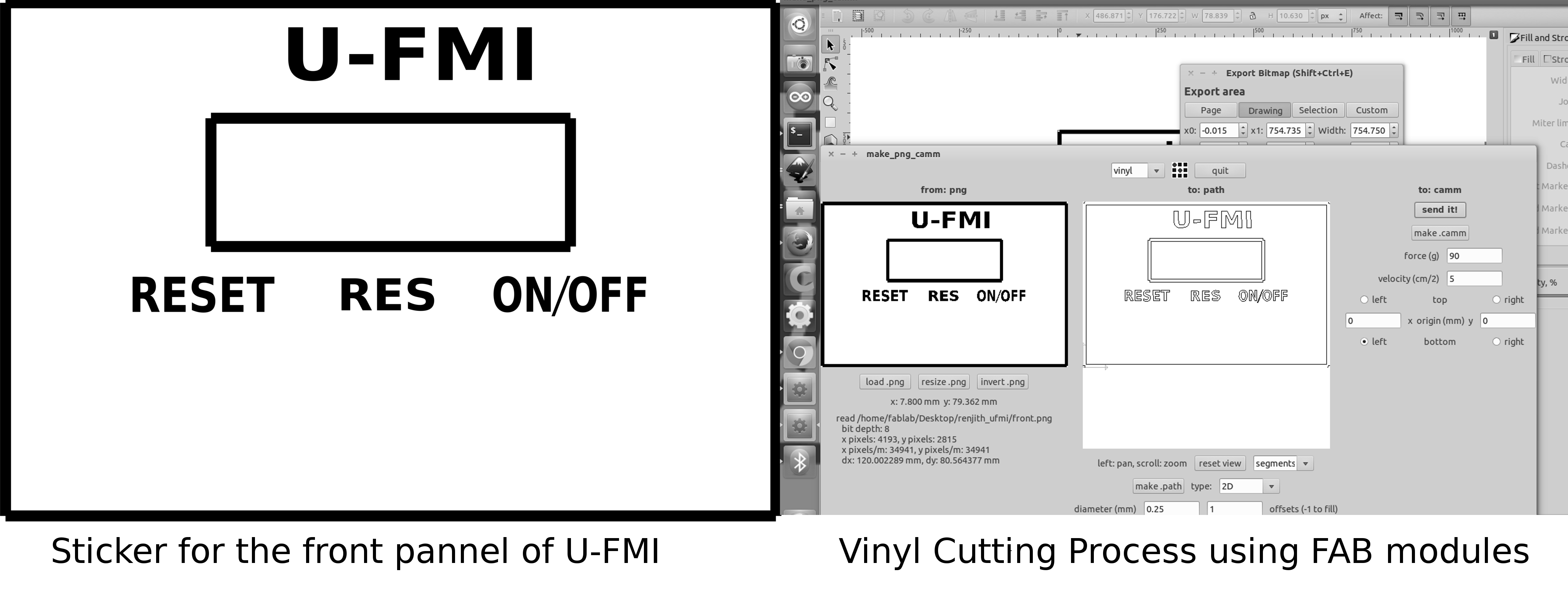
I have exported the rectangular region of the case with provision for switches as DXF file and edited to include the name of my device ,switch label . Then exported the edited file in inkscape as png file.Then I opened the png file in fab modules and done the vinyl cutting procedure.
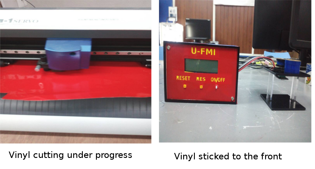
I placed a rectangular piece of yellow vinyl under the Labels so that the labels are seen in yellow color .
The svg file for my Label design is given here
Designing and Laser printing of buttons
Finishing works are going one ,now it is time for designing the button shapes which have to be fixed to the switchs used in U-FMI.
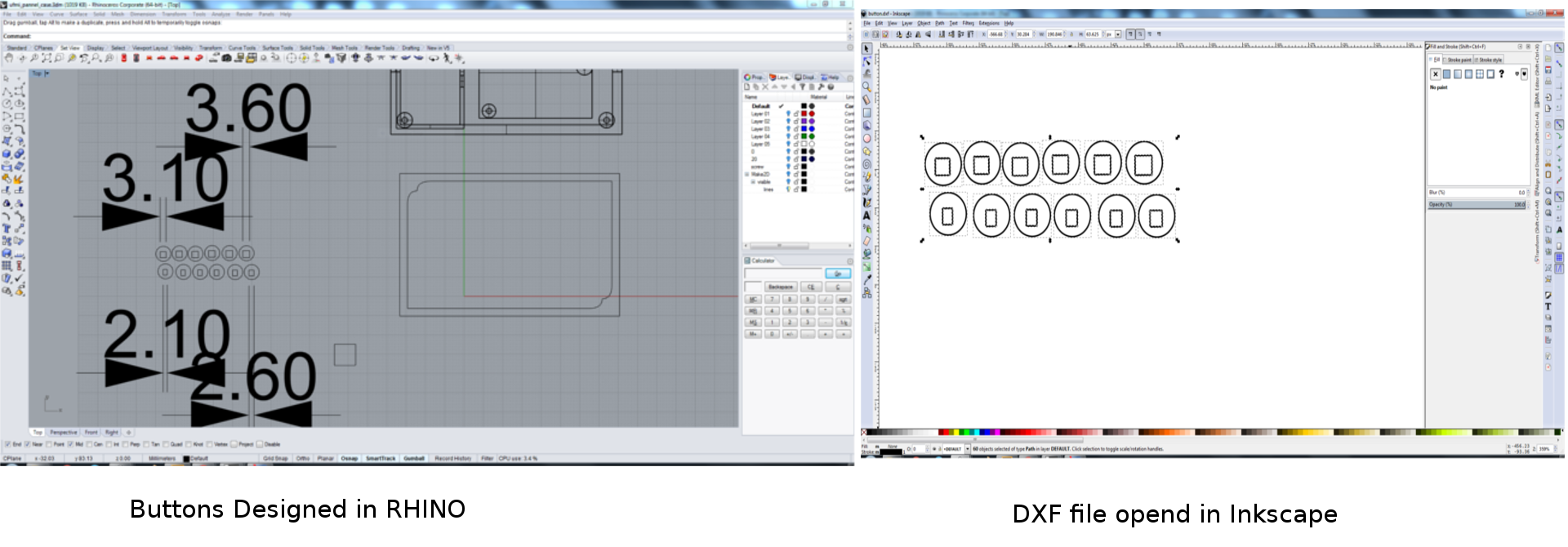
The correct fit is obtained after trial and error method.Two of the seitches used by me have a rectangular head of size 3mm * 3mm and the third switch is having a head size of 2mm * 3 mm.So I need 3 caps of circular shape with a diameter of 8mm with a hollow rectangular region .The dimensions of rectangular region I selected intially was 3 mm * 3 mm,and 3 mm* 2 mm but it was not fitting so I changed little bit and finally the button caps where fixed.
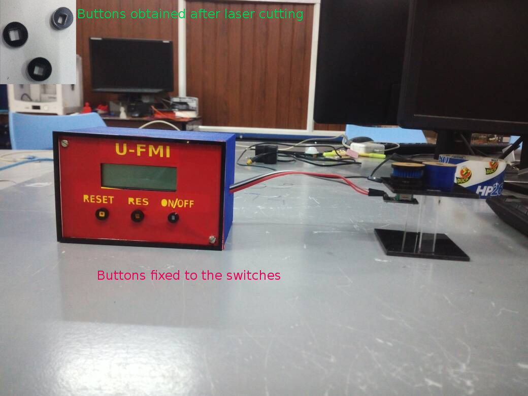
After the buttons where fixed the look of my device got enhanced.The The design file for my button caps are given here
Integrating U-FMI with ULTIMAKER
|
|
|---|
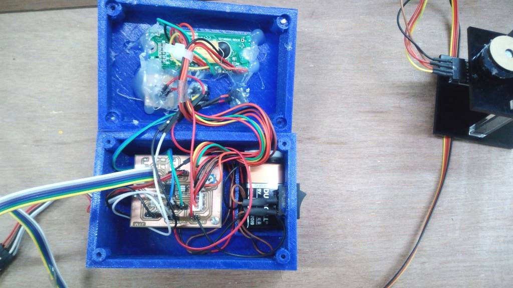
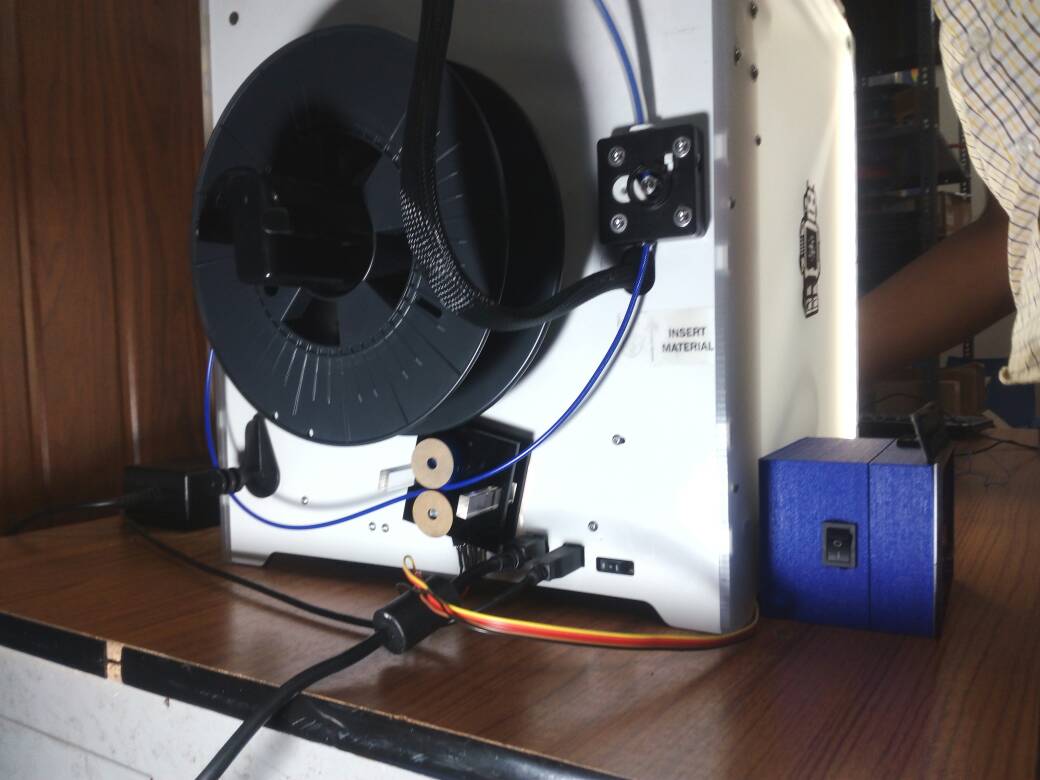
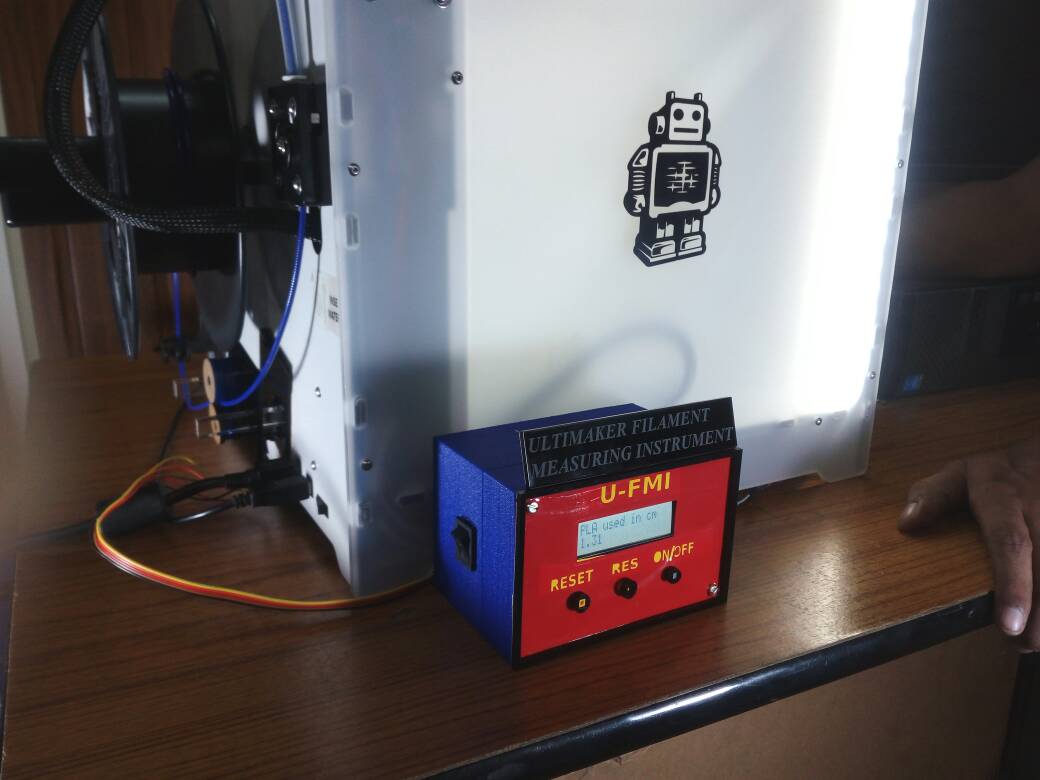
Finally my device ie Ultimaker filament measuring instrument is being mounted to the ultimaker available in our FABLAB.The gear system is fixed to the back of ultimaker using double sided tape .In order to insert the PLA through the gear system of U-FMI ,First of all I removed PLA completely from the ultimaker ,afterwards inserted the PLA through the gap in the gear system ie between the gear on the shaft rotary encoder and the cylindrical disc and further inserted in to the stepper moter of ultimaker sothat it will then be loaded to the machine. The U-FMI starts displaying the length of PLA used in cm but it was able to do the process till grip is avilable in the PLA after that the rotary encoder stops rotating.I used glue over the gear inorder to reduce the gap but unfortunately ultimaker stops working .
So I am concluding that this project will be perfect if the gear system is improved.
CONCLUSION
In my final project I have used the following Processes
| Sl.No | process |
|---|---|
| 1 | PCB DESIGNING AND DIGITAL FABRICATION |
| 2 | COMPUTER AIDED DESIGN AND 3D PRINTING OF CASE |
| 3 | EMBEDDED PROGRAMMING OF ATMEGA328 |
| 4 | LASER CUTTING OF GEAR SYSTEM |
| 5 | VINYL CUTTING OF STICKERS |
DOWNLOAD MY U-FMI PRODUCTION FILES FROM HERE