1. Understanding Attiny 44 - Data Sheet
Other Week Assignment where I mention Data Sheets:
Taking a look to Attiny 44 Data Sheet, a made a summary with the most important parts:
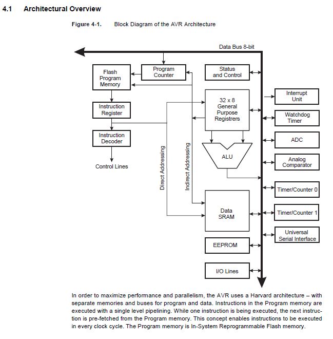
CPU Core - Architectural Overview
Pin Configurations
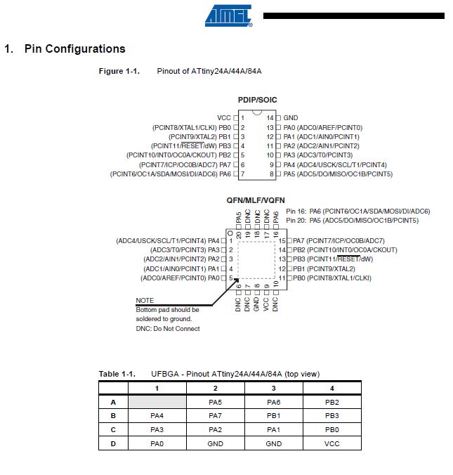
VCC: Supply Voltage
GND: Ground
Port B (PB3: PB0): It is a 4-bit bi-directional I/O Port with internal PULL-UP resistor. As well, port B pins are tri-stated when RESET condition becomes activated.
Reset: reset input. A low level on this pin for nolonger than the minimum pulse length will generate a reset, even if the clock is not running and provided the reset pin has not been disabled.
Port A (PA7:PA0): Port A is a 8-bit bi-directional I/O portwith internet PULL-UP resistors. As well, Port A pins are tri-stated when a reset condition becomes activated.
ALTERNATE PORT FUNCTIONS
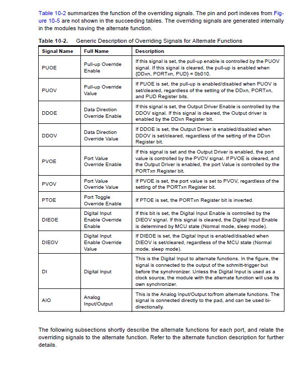
Each port can have an alternate functions, showed on the next table for Port A:
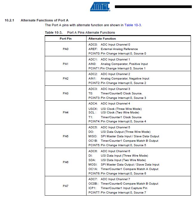
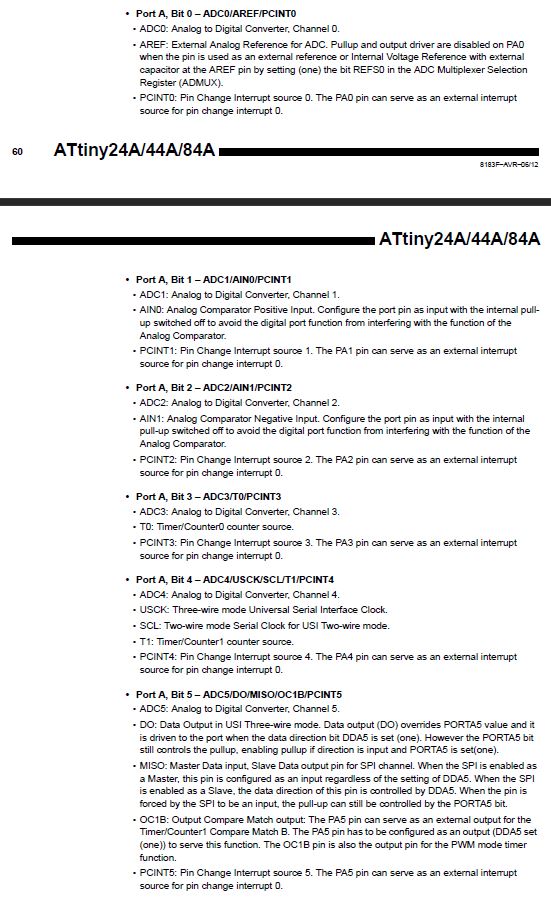
Following this table on the data sheet, we can find the description of each bit of the port, and its main functions:
Each port can have an alternate functions, showed on the next table for Port B:
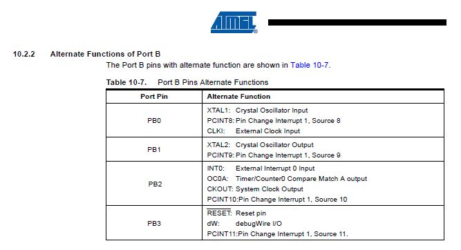
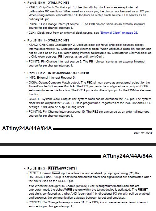
Following this table on the data sheet, we can find the description of each bit of the port, and its main functions:
Memories
The AVR architecture has two main memories spaces, the Data Memory and the Program Memory space. Plus, the ATtiny 44 has an EEPROM Memory for Data storage.
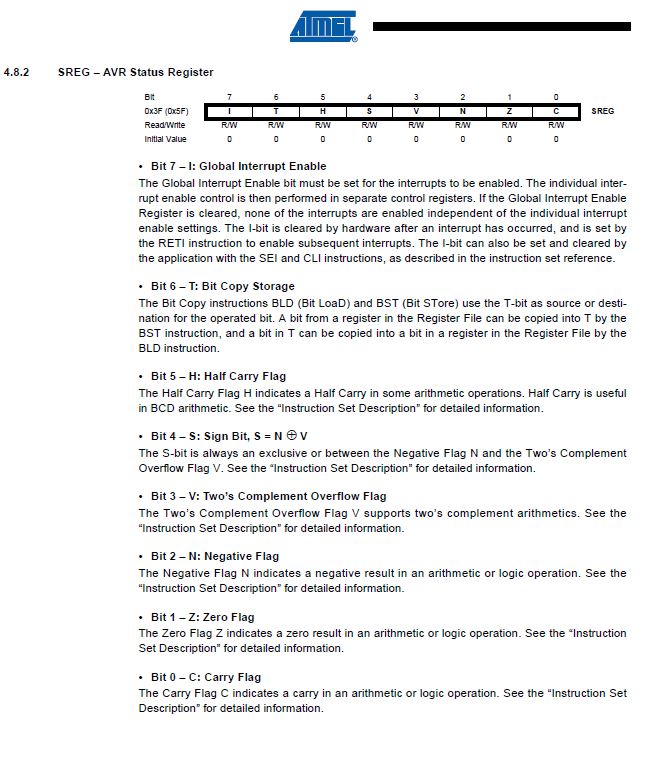
For the 'Register Description' (Port A, Port B), each Port has:
-'Data Register' (PORTA/ PORTB)
- Data Direction Register (DDRA/DDRB)
-Input Pins (PINA, PINB).
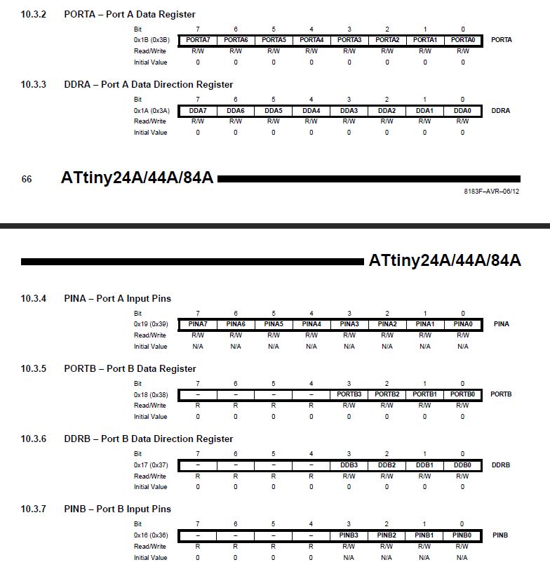
Each register has its own bit coordinate storage, where you can read or write and the initial value that has when running it.
There different types of registers:
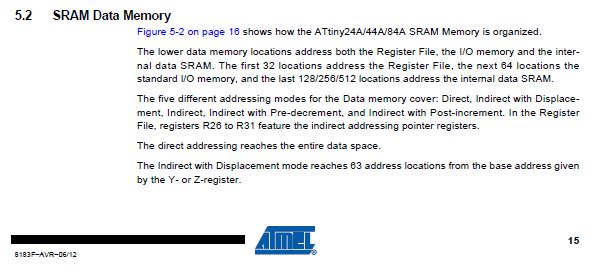
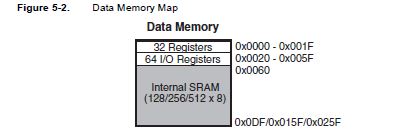
-SRAM (Static Random Access Memory) :
The lower data memory locations address both the Register File (located the first 32 locations), the I/O memory (located the next 64 locations) and the internal data SRAM (located the 256 next ones).
Program's Data - Every time the board is disconnected, all data is erased.
-EEPROM (Electrically Erasable Programmable Read Only Memory):
-The ATtiny 44A contains 256 bytes of data EEPROM.
-It is accessible in the I/O space.
Slower, but the data is stored
- Flash - program's storage
- Fuses - mcu's storage configuration
Clock System
Next diagram represents the principal clock system in the AVR. The clocks not being used at certain times can be halted by using different sleeping modes:
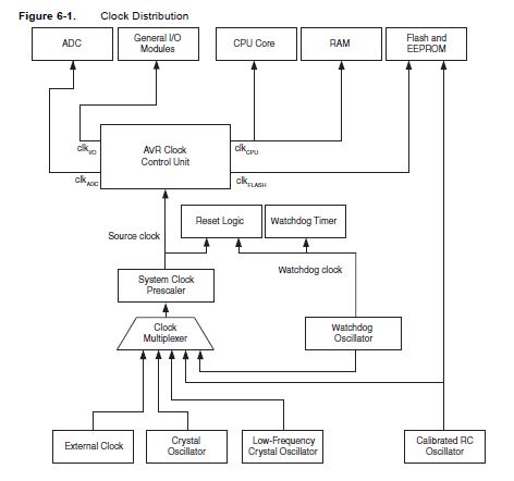
There different clock subsystems:
-CPU Clock: it is related with the operation of the AVR Core.
-I/O Clock: It is used by the majority of the I/O modules (Time/Counter, External Interrupt module and other ones).
-Flash Clock: controls the clock of the flash interface.
-ADC Clock: it has a clock domain allowing the CPU and I/O clocks to halt to reduce noise.
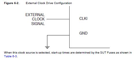
External Clock
In order to have an external clock, this must be connected to CLKI as shown on the diagram below:
External Interrupts
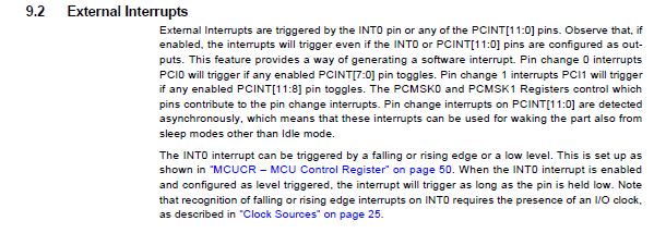
External interrupts are triggered by the INT0 pin or any PCINT pins. If pins are enabled, the interrupt will trigger even if the INT0 or PCINT pins are configured as outputs.
This feature provides a way of generating a software interrupt.
I/O Ports:
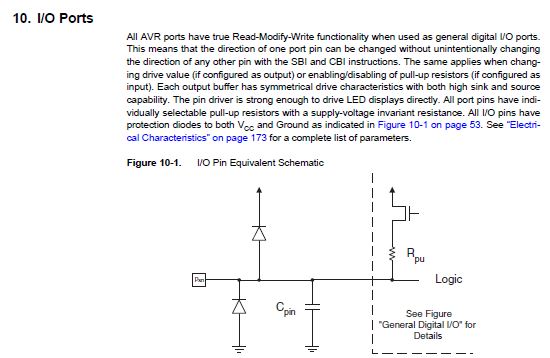
ATtiny 44A has AVR poprts that have true Read-Modifiy- Write functionality when used as digital I/O ports.
Configuring the Pin
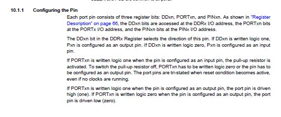
Each port consists of three register bits:
• DDxn:
-the DDxn bit in the DDRx Register selects the direction of this pin. If DDxn is written logic 1, Pxn is configured as an output pin.-If DDxn is written logic 0, Pxn is configured as an input pin.
• PORTxn:
-If Portxn is written logic 1 when the pin is configured as an input pin, the pull-up resistor is activated.-To switch the pull-up resistor off, Portxn has to be written logic 0 or the pin has to be configured as an output pin.
-The port pins are tri-stated when reset condition becomes active, even if no clocks are running.
-If Portxn is written logic 1 when the pin is configured as an output pin, the port pin is driven high (1).
-If Portxn is written logic 0 when the pin is configured as an output pint, the port pin is driven low (0).
Toggling the Pin

Writing a logic one to PINxn toggles the value of PORTxn, independent on the value of DDRxn.
Alternate Functions of Port A
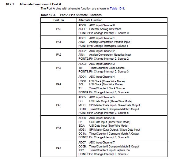
-ADC0: Analog to Digital Converter
-AREF: External Analog Reference for ADC (Analog Digital Converter).
-PCINTx: Pin Change Interrupt Source x.
-ADC: Analog to Digital Converter
-AIN: Analog Comparator Positive Input.
-T0: Timer/Counter0 counter source.
-USCK: Three wire mode Universal Serial Interface Clock.
-SCL: Two-wire mode Serial Clock for USI Two-wire mode.
-DO: Data Output in USI Three-wire mode.
-MISO: Master Data Input, Slave Data output pin for SPI channel.
-OC1B: Output Compare Match output.
-SDA: Two-wire mode Serial Interface Data.
-DI: Data Input in USI Three-wire mode.
-MOSI: MAster Data output, Salve Data input for SPI channel.
-ICPx: Input Capture Pin.
Alternate Funcionts Port B
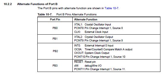
XTAL: Chip Clock Oscillator pin.
PCINTx: Pin Change Interrupt Source x.
CLKI: Clock Input from an external clock source.
OC0A: Output Compare Match output.
CKOUT: System Clock Output.
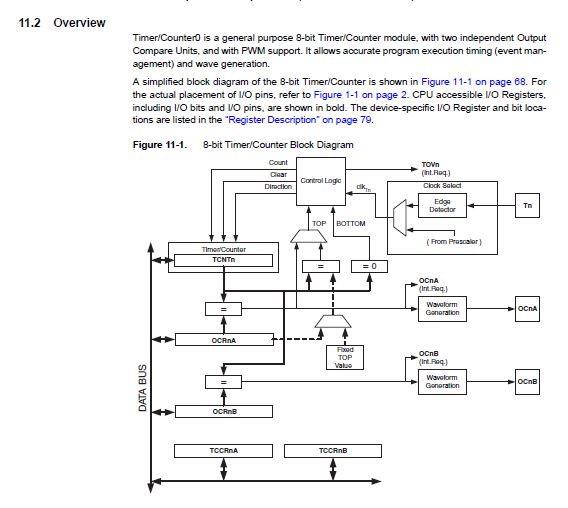
8-Bit Timer/Counter with PWN (Pulse-Width Modulation)
The general purpose of the 8-bit Timer/Counter module allow an accurate program execution timing and wave generation.
Here is a simplified block diagram of the 8-bit Timer/Counter:
Electrical Characteristics
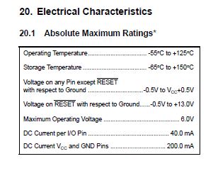
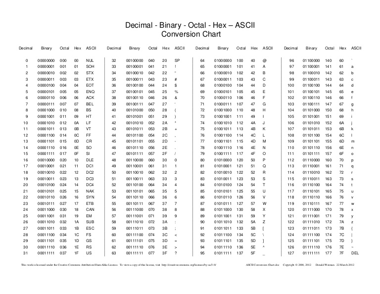
Table - Decimal - Binary - Octal - Hex - ASCII
What questions do you have? What would you like to learn more about?
It is my first time diving myself in a data sheet. It is a challenge for me to understand everything, but after reading and re-reading, creating the board and having our instructor to help us understanding how everything works, it becomes easier.
I want to improve my comprehension in this topic, but it will take a lot of time as now I am not used to think as a programmer. I need first practice, patience and continue working.
I would like to understand better how the memory works. I can tell there are different types of memory that register everything in different ways, but a deeper comprehension is needed. Why some of them are volatile against other ones that are not? How data gets stored when no electrical impulses are taking place? How my computer (PC) really works?
I continually use my computer to make my architectural designs: how a program can work using vectors and represent them the way they do it?
It is a matter of time and emailing my instructor to have a better knowledge of what really is happening inside.