Embedded Programming
Week 8's assignment
- Milling bit : a 1/64inch square bit
- Software :
- Eagle for the design of the board
- V-Carve for the fabrication of the board
- The Arduino IDE for the progammation of the board
This week, we will learn the basics for programming a board.
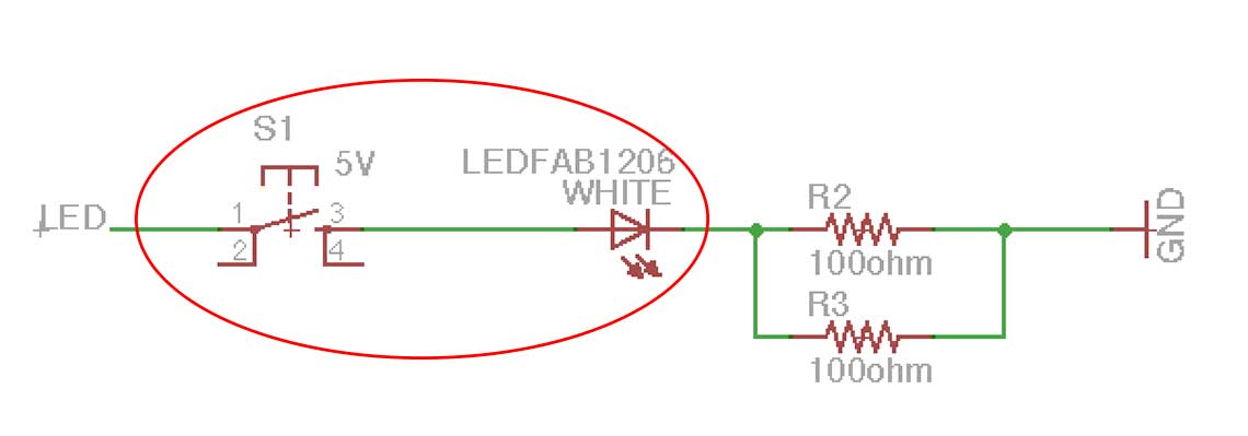
The first thing I wanted to do before even starting to talk about this week, was to design a new version of my Hello FTDI board. The reason for this is because when whe looked back at the one I have already fabricated with our instructor Matthieu, he realized that something was wrong : on my original schematics I had put the LED directly connected to the button (wich was connected to one pin of the ATtiny44). So there would not be much I could do with those, appart from turning on the LED when I pressed the button :
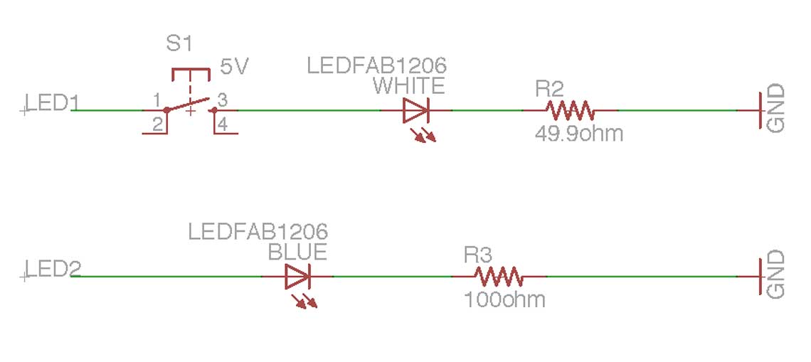
 So I redid my schematic, putting a new LED on the board, this time I chose a blue one and connected to another pin of the ATtiny and therefore independant from the button. The LED not being the same I had to read its data sheet to know what resistance I should use. I put a 100ohm one this time.
I left the other LED connected to the button so that I can turn it on each time the button is pressed to verify it is working well. I also replaced the two parallel 100ohm resistances by a single 49ohm one (I put two in the beginning because we did not have 49 ohm resitances yet). For the selection of the pin, I chose the most convenient one according to the existent traces.
The operation I want to do being quite simple, the choice of the pin does not really matter.
 The first attempt to mill this new version was quite unsuccessfull, I think because the sacrificial layer was too damaged and therefore not flat enough :
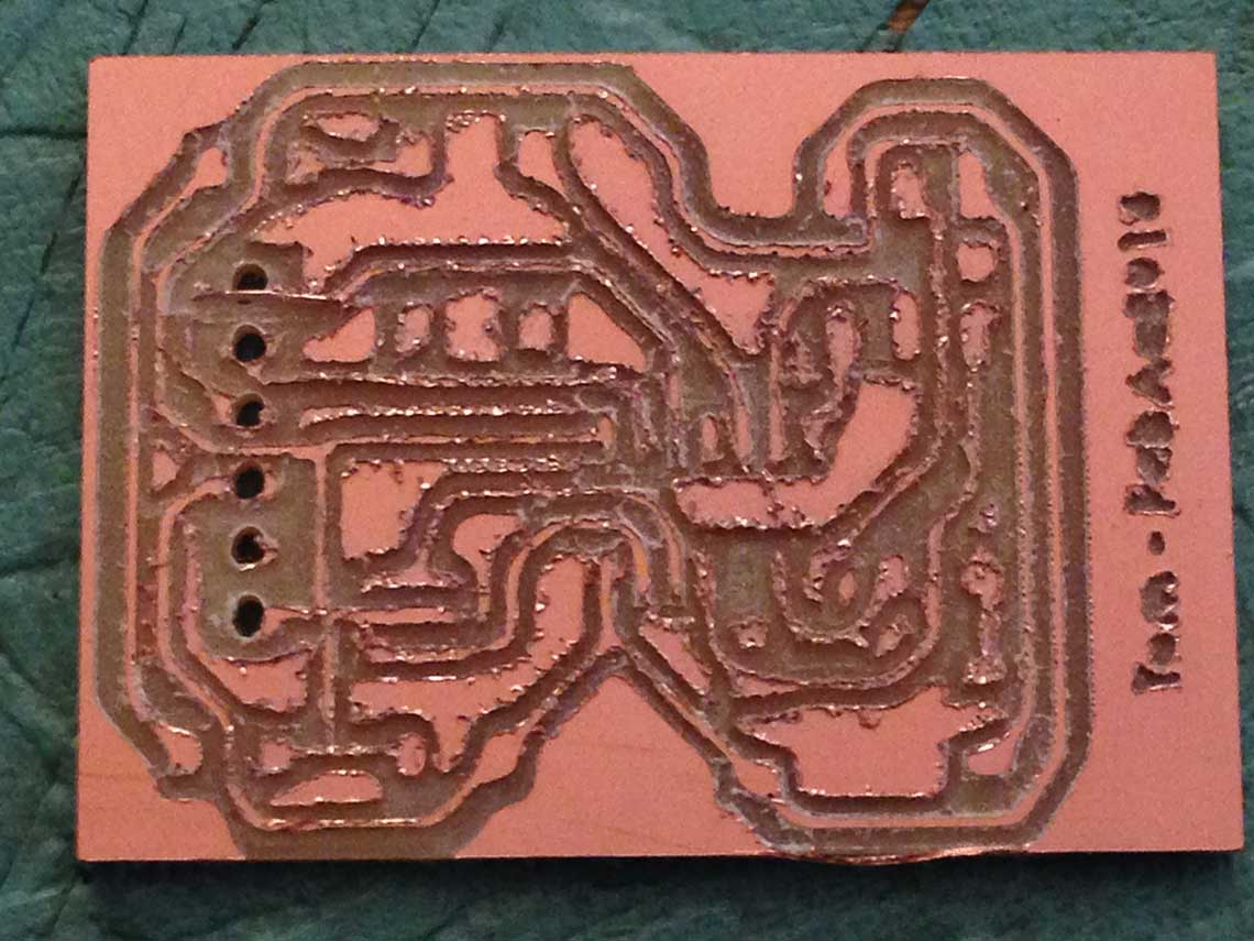 As a result, the traces were too thin, the holes for the FDTI where too big and with no copper around them, and I had to do it all over again.
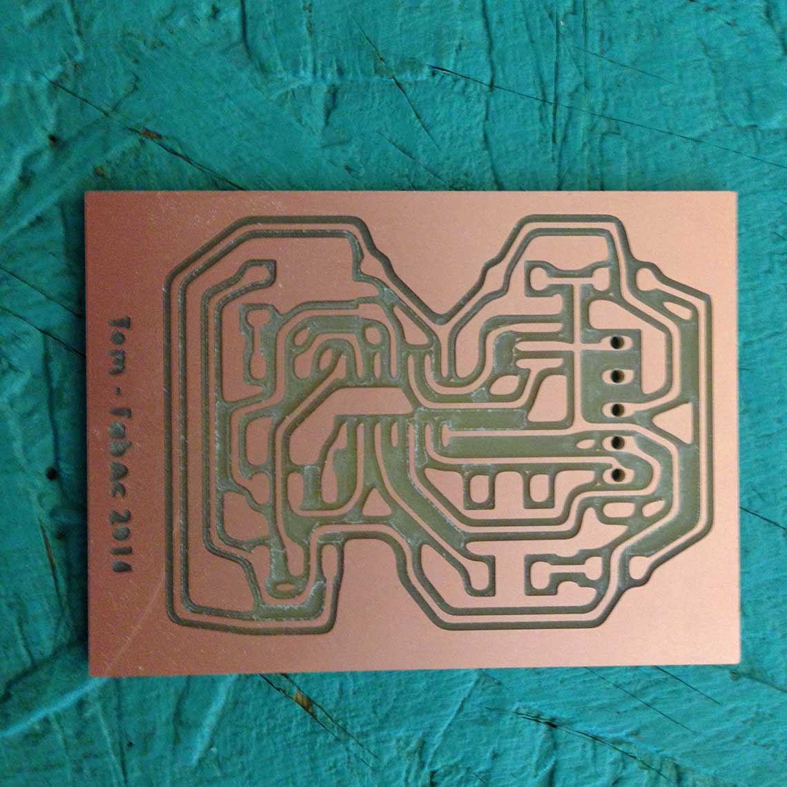
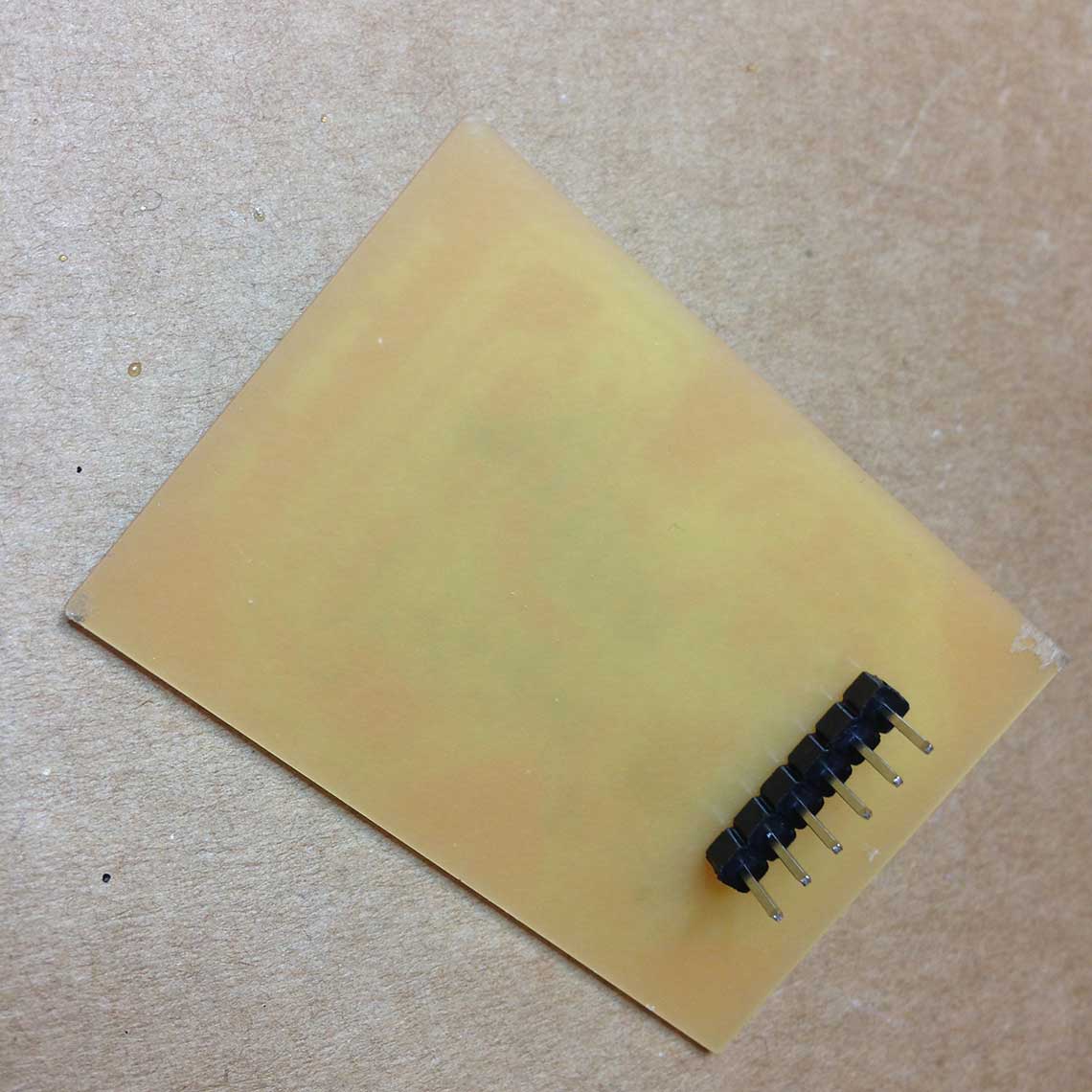
Here is the new board with a clean and flat sacrificial layer :
 And once soldered:
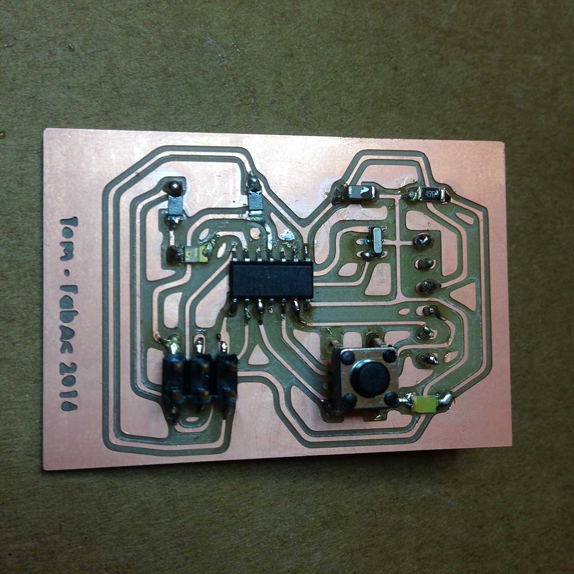
...Or going crazy trying.
 This data sheet is 286 pages long !
I begun to read it at the very end of the week, when I had failed to achieve anything else ;) So I did not go very far, but I took down some notes of what I understood :
- The operating voltagle is between 1.8 to 5.5v. This means that I can use a 5v power source which always good to know.
- "I/O" means Input/Output : if you don't know it, you won't understand much of what is in this datasheet !
- I understood that the pull-up resistors are important notions that allow a specific pin to behave as a stable source of current when the resistor is activated. It prevents from having a floating current. Type A and B pins both all include pull-up resistors. To activate the pull up resistor I will have to specify the High state of the pin I my program. It will be necessary for the button pin.
- The "overview" paragraph and especially the one on page5 is an interesting and important start because everthing the ATtiny44 does or can do is summarized there.
- This data sheet includes code examples, which could be very usefull in the future
- Although for the moment my konwledge does not allow me to understand the details, the Clock section (p25) of the date sheet will certainly be usefull for my final project. I will need to have a very precise clock system, so it is better if I use an external clock.
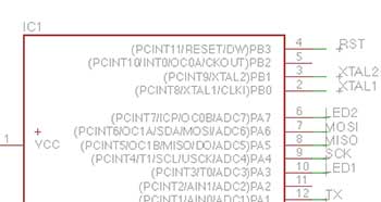
- The table 10.3 on page 60 is important to know what are the alternate functions of each pin. I connected the LED to PA7 (or pin6), so I know that it can be used, like all pins, as an ADC input.
- Three of the pins are output for the PWM mode function : PA6, PA7 and PB2. PWM, or Pulse Width Modulation rapidly turns the output pin high and low over a fixed period of time. This acts as if the voltage was changing. The data sheet provides formulas to calculate what should be the PMW frequency.
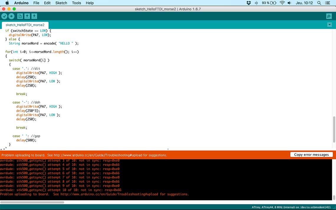
This step was not completed this week because we did not achieve in turning the FabISP into a programmer in the first place. We had two complete ISPs but neither of them worked. See documentation on Week4 for more details.
3. Writting the program and running it
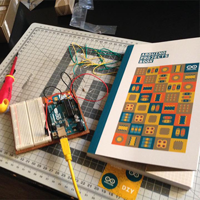
The first thing I wanted to do was to try the program on an Arduino UNO board before loading it into the Hello board. I already now a few basics of C, having completed the first 8 projects of the Arduino Starter Kit that I bought just before the beginning of the Fab Academy this year !
 So I wrote this very simple script, based on the "Spaceship Interface" code for the Project 2 of the Arduino Project Book :
    int switchState = 0;

    void setup() {
      // put your setup code here, to run once:
      pinMode(3, OUTPUT);
      pinMode(2, INPUT);
    }

    void loop() {
      // put your main code here, to run repeatedly:
      switchState = digitalRead(2);

      if (switchState == LOW) {
        digitalWrite(3, LOW);
      }
      else {
        delay(500);
        digitalWrite(3, HIGH);
        delay(500);
        digitalWrite(3, LOW);
        delay(500);
        digitalWrite(3, HIGH);
        delay(500);
        digitalWrite(3, LOW);
        delay(500);
        digitalWrite(3, HIGH);
        delay(500);
      }
    }
Here is what it does when loaded into the Arduino UNO :It is pretty simple and I wanted to test something more elaborated so I also did this version, based on a example I found here. This script tells the LED to say "hello" in morse code when then button is pressed :
      int switchState = 0;

    //morse code mapping
    static const struct {const char letter, *code;} MorseMap[] =
    {
      { 'A', ".-" },
      { 'B', "-..." },
      { 'C', "-.-." },
      { 'D', "-.." },
      { 'E', "." },
      { 'F', "..-." },
      { 'G', "--." },
      { 'H', "...." },
      { 'I', ".." },
      { 'J', ".---" },
      { 'K', ".-.-" },
      { 'L', ".-.." },
      { 'M', "--" },
      { 'N', "-." },
      { 'O', "---" },
      { 'P', ".--." },
      { 'Q', "--.-" },
      { 'R', ".-." },
      { 'S', "..." },
      { 'T', "-" },
      { 'U', "..-" },
      { 'V', "...-" },
      { 'W', ".--" },
      { 'X', "-..-" },
      { 'Y', "-.--" },
      { 'Z', "--.." },
      { ' ', "     " }, //Gap between word, seven units

      { '1', ".----" },
      { '2', "..---" },
      { '3', "...--" },
      { '4', "....-" },
      { '5', "....." },
      { '6', "-...." },
      { '7', "--..." },
      { '8', "---.." },
      { '9', "----." },
      { '0', "-----" },

      { '.', "·–·–·–" },
      { ',', "--..--" },
      { '?', "..--.." },
      { '!', "-.-.--" },
      { ':', "---..." },
      { ';', "-.-.-." },
      { '(', "-.--." },
      { ')', "-.--.-" },
      { '"', ".-..-." },
      { '@', ".--.-." },
      { '&', ".-..." },
    };

    void setup() {
      // put your setup code here, to run once:
      pinMode(3, OUTPUT);
      pinMode(2, INPUT);
      // to activate the pull-up resistor :
      digitalWrite(2, HIGH);
    }

    void loop() {
      // put your main code here, to run repeatedly:
      switchState = digitalRead(2);

      if (switchState == LOW) {
        digitalWrite(3, LOW);
      }
      else {
        String morseWord = encode( "HELLO " );

      for(int i=0; i<=morseWord.length(); i++)
      {
        switch( morseWord[i] )
        {
          case '.': //dit
            digitalWrite(3, HIGH );
            delay(250);
            digitalWrite(3, LOW );
            delay(250);

            break;

          case '-': //dah
            digitalWrite(3, HIGH );
            delay(250*3);
            digitalWrite(3, LOW );
            delay(250);

            break;

          case ' ': //gap
            delay(500);
        }
      }
     }
    }

    String encode(const char *string)
    {
      size_t i, j;
      String morseWord = "";

      for( i = 0; string[i]; ++i )
      {
        for( j = 0; j < sizeof MorseMap / sizeof *MorseMap; ++j )
        {
          if( toupper(string[i]) == MorseMap[j].letter )
          {
            morseWord += MorseMap[j].code;
            break;
          }
        }
        morseWord += " "; //Add tailing space to seperate the chars
      }

      return morseWord;
    }
And it works ! Let's note that the morse code for "HELLO" is (H)•••• (E)• (L)•—•• (L)•—•• (O)——— :
Of course I will have to change the pin numbers in the code to make them match to the ATTiny44 :
 So pin3 becomes PA7 (the blue LED) and pin2 becomes PA3 (the button):
                            void setup() {
                              // put your setup code here, to run once:
                              pinMode(PA7, OUTPUT);
                              pinMode(PA3, INPUT);
                            }
Then my main concern was to understand how I could program by Hello board directly without the FabISP which was not yet workind, using and Arduino UNO as an ISP. So first I uploaded the Arduino ISP sketch to the Arduino UNO and connected some LED's to the breadboard, as instructed in the sketch :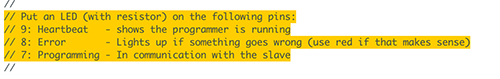 We can see here that the first LED is on (actually it is pulsating), which indicates that the ISP program runs successfully :
 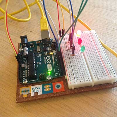 To load the sketch I wrote into my Hello board, I chose the option "upload using a programmer" in the sketch menu, but it returned the same error as we had before with the FabISP regarding the identification of the device :"Unrecognized device". The red LED turned on to indicate an error... At least the Arduino ISP program is working fine :p
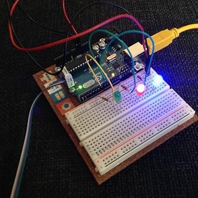
 Update 14th April
Because of the group assignment, I must admit I fell a little behind on the subject of programming my Hello Board... I had a lot of trouble understanding how to load my program into the PCB. But I was kindly helped by one of my fellow students, Roman, who showed me how to load a program on the board using Arduino ISP and then Xcode. He gave my a test script which reproduces the blink sketch from Arduino :
    #include
    #include


    #ifndef cbi
    #define cbi(sfr, bit) (_SFR_BYTE(sfr) &= ~_BV(bit))
    #endif
    #ifndef sbi
    #define sbi(sfr, bit) (_SFR_BYTE(sfr) |= _BV(bit))
    #endif


    int main(void)
    {
       sbi(PORTA, PA7); // Set PA7 for output

       for(;;){
               sbi(PORTA, PA7); // LED is ON
               _delay_ms(100);
               cbi(PORTA, PA7); // LED is OFF
               _delay_ms(100);
       }
       return 0;
    }
Using XcodeI created a new project with parameters corresponding to my board (identifying the righ microcontroller, frequency, etc.) and then I simply had to hit the "build" button to send the program to the board. It worked immediately so I was relieved because at first, I was afraid something was wrong with the circuit itself... Here is a video of the result :After it was a little more difficult because I had to rewrite my code in real C in order to make it work. Being a complete beginer in programming, I made the mistake of thinking that Arduino and C were exactly the same, but it is not true. Roman showed me how to modify the most essential parts of the orginal Arduino sketch, and then let me "translate the rest in C"... Here is the C version of the code :
    #include
    #include
    #include
    #include
    #include

    #ifndef cbi
    #define cbi(sfr, bit) (_SFR_BYTE(sfr) &= ~_BV(bit))
    #endif
    #ifndef sbi
    #define sbi(sfr, bit) (_SFR_BYTE(sfr) |= _BV(bit))
    #endif

    int switchState = 0;

    //morse code mapping
    static const struct {const char letter, *code;} MorseMap[] =
    {
        { 'A', ".-" },
        { 'B', "-..." },
        { 'C', "-.-." },
        { 'D', "-.." },
        { 'E', "." },
        { 'F', "..-." },
        { 'G', "--." },
        { 'H', "...." },
        { 'I', ".." },
        { 'J', ".---" },
        { 'K', ".-.-" },
        { 'L', ".-.." },
        { 'M', "--" },
        { 'N', "-." },
        { 'O', "---" },
        { 'P', ".--." },
        { 'Q', "--.-" },
        { 'R', ".-." },
        { 'S', "..." },
        { 'T', "-" },
        { 'U', "..-" },
        { 'V', "...-" },
        { 'W', ".--" },
        { 'X', "-..-" },
        { 'Y', "-.--" },
        { 'Z', "--.." },
        { ' ', "     " }, //Gap between word, seven units

        { '1', ".----" },
        { '2', "..---" },
        { '3', "...--" },
        { '4', "....-" },
        { '5', "....." },
        { '6', "-...." },
        { '7', "--..." },
        { '8', "---.." },
        { '9', "----." },
        { '0', "-----" },

        { '.', "·–·–·–" },
        { ',', "--..--" },
        { '?', "..--.." },
        { '!', "-.-.--" },
        { ':', "---..." },
        { ';', "-.-.-." },
        { '(', "-.--." },
        { ')', "-.--.-" },
        { '"', ".-..-." },
        { '@', ".--.-." },
        { '&', ".-..." },
    };

    //char encode(const char *string)
    char encode(char string[])
    {
        size_t i, j;
        //char morseWord[]="";
        char toto[]="";

        //for( i = 0; string[i]; ++i )
        for( i = 0; strlen(string); ++i )
        {
            for( j = 0; j < sizeof MorseMap / sizeof *MorseMap; ++j )
            {
            if( toupper(string[i]) == MorseMap[j].letter )
                {
                     strcat(toto, MorseMap[j].code);
                    break;
                }
            }
             strcat(toto," "); //Add tailing space to seperate the chars
        }

        return *string;
    //    return *morseWord;
    }


    int main(void)
    {
        sbi(PORTA, PA7); // Set PA7 for output (sbi = set bit)
        cbi(DDRA, PA3); // Set PA3 for input (cbi = clear bit)
        sbi(PORTA, PA3); // Pull-up resistor activated on PA3

        sbi(PORTA, PA7);
        _delay_ms(100);
        cbi(PORTA, PA7);
        _delay_ms(100);

        for(;;){
    //        switchState = digitalRead(PA3);

            if (switchState == 0) {
                cbi(PORTA, PA7);
            } else {
                //char morseWord[] = "";
                //char morseWord[] = encode( "hello " );
                char toto[] = encode( "HELLO " );
                //char morseWord[] = "--.";

                for(int i=0; i<=strlen(toto); i++)
                {
                    char Zozo = toto[i];
                    switch( Zozo )
                    {
                        case '.': //court
                            sbi(PORTA, PA7);
                            _delay_ms(250);
                            cbi(PORTA, PA7);
                            _delay_ms(250);

                            break;

                        case '-': //long
                            sbi(PORTA, PA7);
                            _delay_ms(250*3);
                            cbi(PORTA, PA7);
                            _delay_ms(250);

                            break;

                        case ' ': //blanc
                            _delay_ms(500);
                    }
                }
            }
        }
        return 1;
    }