Output Devices
Week 13's assignment
Specific material and softwares used during this assignment
- Machine : CNC mill for the fabrication of the PCB
- Software :
- V-Carve for the G-code
- Arduino IDE for the program
- 123Dcircuits for simulation
- Electronic devices :
- a HC-SR04 Ping sensor as an input
- a RGB LED as an ouput
- 12 red LEDs
- Software :
- V-Carve for the G-code
- Arduino IDE for the program
- 123Dcircuits for simulation
- Electronic devices :
- a HC-SR04 Ping sensor as an input
- a RGB LED as an ouput
- 12 red LEDs
As an introduction, I would say that, like M. Burns and Smitters, all these LEDs drove my a bit crazy !

Tests with LEDs
To start this week I wanted to use the distance sensor again and make it communicate with a output device. My idea was to use a color LED as a indicator of distance. Basically, I tell the LED to react differently according to the distance measured by the HC-SR04 : when I am at a certain distance, the LED is green and the closer I get, the more the LED gets red. For the moment I only defined three color states, green, yellow and red, but In the end I'd like to have a constant variation of the color according to the distance. Here is the Arduino sketch :
  #define trigPin 6
  #define echoPin 7
  #define redLEDPin 10
  #define blueLEDPin 11
  #define greenLEDPin 9

  int redValue = 0;
  int blueValue = 0;
  int greenValue = 0;

  void setup() {
    Serial.begin (9600);
    pinMode(trigPin, OUTPUT);
    pinMode(echoPin, INPUT);
    for(int pinNumber = 9; pinNumber<12; pinNumber++){
      pinMode(pinNumber, OUTPUT);
      //digitalWrite(pinNumber, LOW);
    }
  }

  void loop() {
    long duration, distance;
    digitalWrite(trigPin, LOW);
    delayMicroseconds(2);
    digitalWrite(trigPin, HIGH);
    delayMicroseconds(10);
    digitalWrite(trigPin, LOW);
    duration = pulseIn(echoPin, HIGH);
    distance = (duration/2) / 29.1;
    Serial.println(distance);
    delay(1);
   //read the distance value and change the color of the LED according to it.
   if(distance<10){
    redValue = 255;
    greenValue = 0;
    blueValue = 0;
   }
   else if(distance >=10 && distance < 20){
    redValue = 100;
    greenValue = 255;
    blueValue = 0;
   }
   else if(distance >=20){
    redValue = 0;
    greenValue = 255;
    blueValue = 0;
   }

    analogWrite(redLEDPin, redValue);
    analogWrite(blueLEDPin, blueValue);
    analogWrite(greenLEDPin, greenValue);

    delay(1);
  }
For testing I used an Arduino board with the sensor and a RGB. Each color pin of the LED is connected to the Arduino through a 220ohm resistor.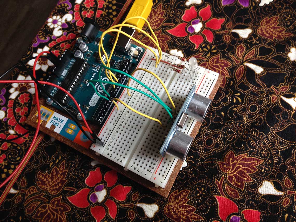 I works like this :
Then I modified the code to have a progressive change of the color of the LED :
  #define trigPin 6
  #define echoPin 7
  #define redLEDPin 10
  #define blueLEDPin 11
  #define greenLEDPin 9

  int redValue = 0;
  int blueValue = 0;
  int greenValue = 0;

  void setup() {
    Serial.begin (9600);
    pinMode(trigPin, OUTPUT);
    pinMode(echoPin, INPUT);
    for(int pinNumber = 9; pinNumber<12; pinNumber++){
      pinMode(pinNumber, OUTPUT);
      //digitalWrite(pinNumber, LOW);
    }
  }

  void loop() {
    long duration, distance;
    digitalWrite(trigPin, LOW);
    delayMicroseconds(2);
    digitalWrite(trigPin, HIGH);
    delayMicroseconds(10);
    digitalWrite(trigPin, LOW);
    duration = pulseIn(echoPin, HIGH);
    distance = (duration/2) / 29.1;
    Serial.println(distance);
    delay(1);
   //read the distance value and change the color of the LED according to it.

    redValue = 255-(distance*4);
    greenValue = distance*4;
    blueValue = 0;

    analogWrite(redLEDPin, redValue);
    analogWrite(blueLEDPin, blueValue);
    analogWrite(greenLEDPin, greenValue);

    delay(1);
  }
And the proof video of this code :Charlieplexing
Making the PCBThis is all great but thinking back, I realized it would be better to try something more related to my final project. Neil showed us an example of Charlieplexing during this week's class and our instructor Fabien also talked about it in his presentation that you can find here. Since I will be using multiple LED's to mark the hours on my clock, I will need this technique, so I am going to try it this week. First of wall I did some more research to learn more about how Charlieplexing works. I found some very useful information to start on this Wikipedia page. This statement is good way to understand it :
Microcontroller pins generally have three states: "high" (5 V), "low" (0 V) and "input". Input mode puts the pin into a high-impedance state, which, electrically speaking, "disconnects" that pin from the circuit, meaning little or no current will flow through it. This allows the circuit to see any number of pins connected at any time, simply by changing the state of the pin.
Another very important information is this equation which determines how much pins you need depending on how much LEDs you want to use :
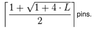 I'am going to be using 12 LEDs because I want to create a simple clock counting only hours. So according to this formula, I will need 4 pins.
For this first test of Charlieplexing method, I don't want to complicate things too much so all the LEDs I will use will be identical (same color). This way, I will only need one resistor per row, so I'll need 4 of them.
I chose red LEDs. The ones we have are these.
According to the data sheet, the forward voltage is 2.1 and the forward current is 30mA, so I will need 100ohm resistors.
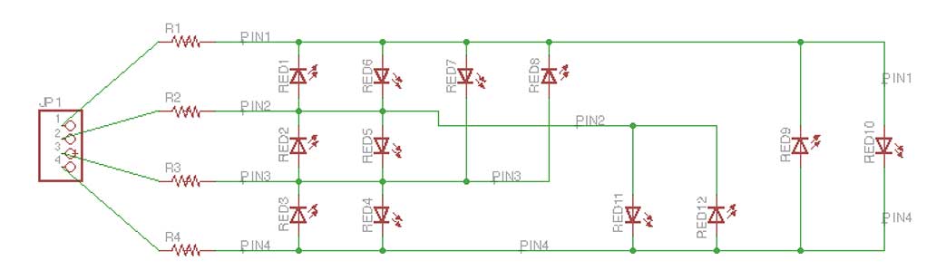
My idea is to make a simple board with only the LEDs, the resistors and some header pins, to connect the board to the SatchaKit that I made for the Input Devices assiment. Here is the Eagle schematic of my clock board :
 And I spent quite some time on the board design, because I wanted the LEDs to be displayed on a circle, like a regular clock face. The tricky part being to know how to orient the LEDs, I added some + symbols next to the anodes to avoid any mistake when soldering :
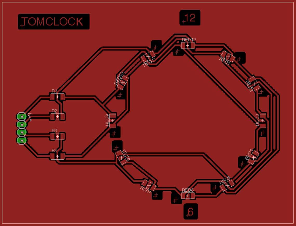
Update ...
I finally could make my PCB, with the Roland Monofab, and the result is just great (I removed the + signs that where suposed to help me know which way to put the LEDs, because Fabmodules was having trouble interpreting them).
These are the settings used in the Fabmodule, with a 1/64 end mill (0.39mm) :
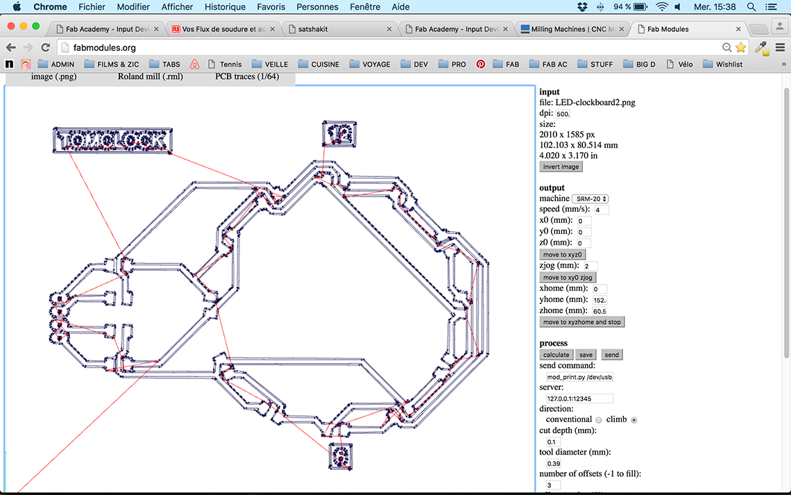 And here is the milled board :
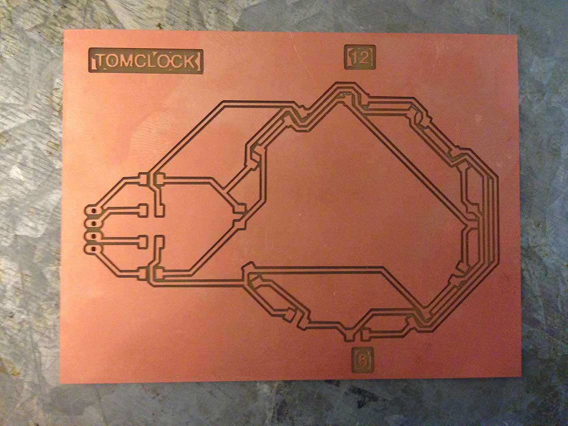 And soldered :
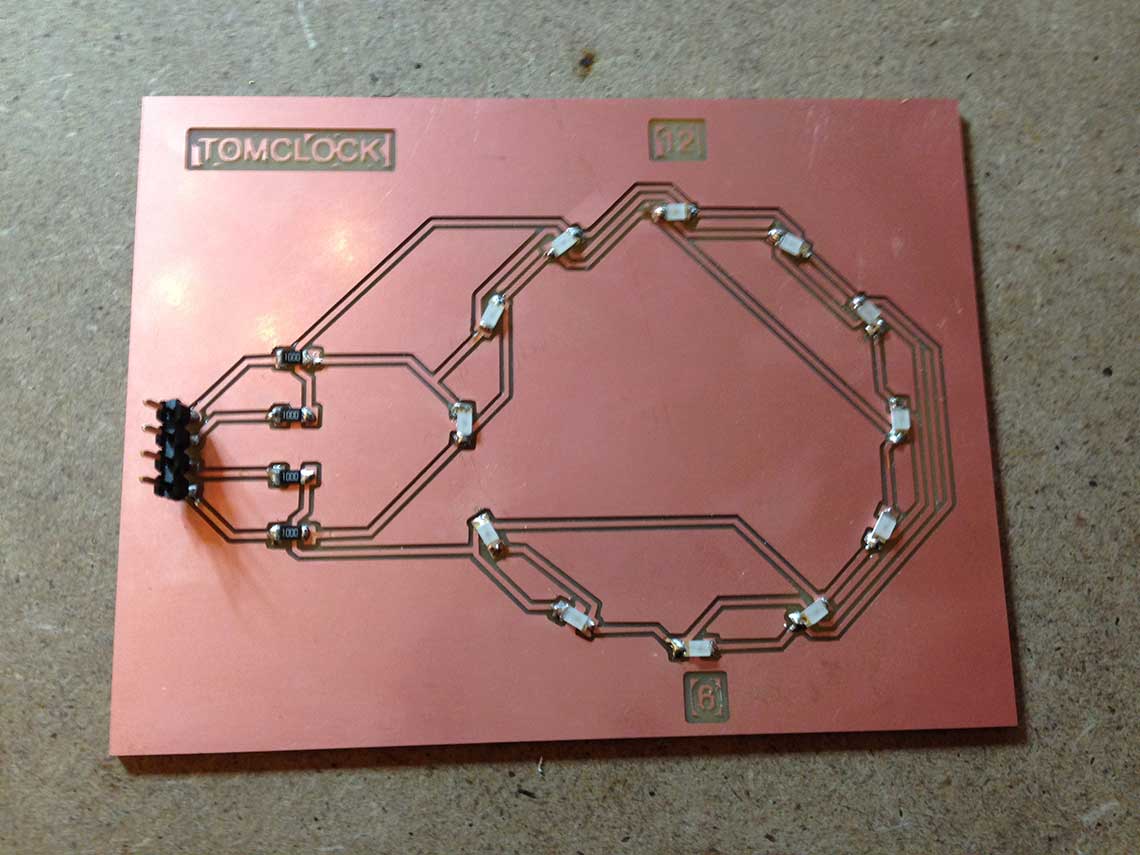
Writing the program
The hardest part for me was to understand how to control the LEDs on a Charlieplexing pattern. I found several examples of Arduino code and it took me quite some time to figure this out. Finally, based on this Instructable, I wrote this pretty basic piece of code :
    /* Charliplexing 12 LEDs
    const int LED_1 = 13;     //LED row 1
    const int LED_2 = 12;     //LED row 2
    const int LED_3 = 11;     //LED row 3
    const int LED_4 = 10;     //LED row 4

    void setup()
    {

    }

    void loop()
    {
      //turn on LED L1
      pinMode(LED_1, OUTPUT);     //row 1
      digitalWrite(LED_1, LOW);
      pinMode(LED_2, OUTPUT);     //row 2
      digitalWrite(LED_2, HIGH);
      pinMode(LED_3, INPUT);      //row 3
      digitalWrite(LED_3, LOW);
      pinMode(LED_4, INPUT);      //row 4
      digitalWrite(LED_4, LOW);

      delay(2000);

      //turn on LED L2
      pinMode(LED_1, INPUT);     //row 1
      digitalWrite(LED_1, LOW);
      pinMode(LED_2, OUTPUT);     //row 2
      digitalWrite(LED_2, LOW);
      pinMode(LED_3, OUTPUT);      //row 3
      digitalWrite(LED_3, HIGH);
      pinMode(LED_4, INPUT);      //row 4
      digitalWrite(LED_4, LOW);

      delay(2000);

       //turn on LED L3
      pinMode(LED_1, INPUT);     //row 1
      digitalWrite(LED_1, LOW);
      pinMode(LED_2, INPUT);     //row 2
      digitalWrite(LED_2, LOW);
      pinMode(LED_3, OUTPUT);      //row 3
      digitalWrite(LED_3, LOW);
      pinMode(LED_4, INPUT);      //row 4
      digitalWrite(LED_4, HIGH);

      delay(2000);

       //turn on LED L4
      pinMode(LED_1, INPUT);     //row 1
      digitalWrite(LED_1, LOW);
      pinMode(LED_2, INPUT);     //row 2
      digitalWrite(LED_2, LOW);
      pinMode(LED_3, OUTPUT);      //row 3
      digitalWrite(LED_3, HIGH);
      pinMode(LED_4, INPUT);      //row 4
      digitalWrite(LED_4, LOW);

      delay(2000);

        //turn on LED L5
      pinMode(LED_1, INPUT);     //row 1
      digitalWrite(LED_1, LOW);
      pinMode(LED_2, OUTPUT);     //row 2
      digitalWrite(LED_2, HIGH);
      pinMode(LED_3, OUTPUT);      //row 3
      digitalWrite(LED_3, LOW);
      pinMode(LED_4, INPUT);      //row 4
      digitalWrite(LED_4, LOW);

      delay(2000);

      //turn on LED L6
      pinMode(LED_1, OUTPUT);     //row 1
      digitalWrite(LED_1, HIGH);
      pinMode(LED_2, OUTPUT);     //row 2
      digitalWrite(LED_2, LOW);
      pinMode(LED_3, INPUT);      //row 3
      digitalWrite(LED_4, LOW);
      pinMode(LED_4, INPUT);      //row 4
      digitalWrite(LED_4, LOW);

      delay(2000);

      //turn on LED L7
      pinMode(LED_1, OUTPUT);     //row 1
      digitalWrite(LED_1, HIGH);
      pinMode(LED_2, INPUT);     //row 2
      digitalWrite(LED_2, LOW);
      pinMode(LED_3, OUTPUT);      //row 3
      digitalWrite(LED_3, LOW);
      pinMode(LED_4, INPUT);      //row 4
      digitalWrite(LED_4, LOW);

      delay(2000);

      //turn on LED L8
      pinMode(LED_1, OUTPUT);     //row 1
      digitalWrite(LED_1, LOW);
      pinMode(LED_2, INPUT);     //row 2
      digitalWrite(LED_2, LOW);
      pinMode(LED_3, OUTPUT);      //row 3
      digitalWrite(LED_3, HIGH);
      pinMode(LED_4, INPUT);      //row 4
      digitalWrite(LED_4, LOW);

      delay(2000);

      //turn on LED L9
      pinMode(LED_1, OUTPUT);     //row 1
      digitalWrite(LED_1, LOW);
      pinMode(LED_2, INPUT);     //row 2
      digitalWrite(LED_2, LOW);
      pinMode(LED_3, INPUT);      //row 3
      digitalWrite(LED_3, LOW);
      pinMode(LED_4, OUTPUT);      //row 4
      digitalWrite(LED_4, HIGH);

      delay(2000);

      //turn on LED L10
      pinMode(LED_1, OUTPUT);     //row 1
      digitalWrite(LED_1, HIGH);
      pinMode(LED_2, INPUT);     //row 2
      digitalWrite(LED_2, LOW);
      pinMode(LED_3, INPUT);      //row 3
      digitalWrite(LED_3, LOW);
      pinMode(LED_4, OUTPUT);      //row 4
      digitalWrite(LED_4, LOW);

      delay(2000);

      //turn on LED L11
      pinMode(LED_1, INPUT);     //row 1
      digitalWrite(LED_1, LOW);
      pinMode(LED_2, OUTPUT);     //row 2
      digitalWrite(LED_2, HIGH);
      pinMode(LED_3, INPUT);      //row 3
      digitalWrite(LED_3, LOW);
      pinMode(LED_4, OUTPUT);      //row 4
      digitalWrite(LED_4, LOW);

      delay(2000);

      //turn on LED L12
      pinMode(LED_1, INPUT);     //row 1
      digitalWrite(LED_1, LOW);
      pinMode(LED_2, OUTPUT);     //row 2
      digitalWrite(LED_2, LOW);
      pinMode(LED_3, INPUT);      //row 3
      digitalWrite(LED_3, LOW);
      pinMode(LED_4, OUTPUT);      //row 4
      digitalWrite(LED_4, HIGH);

      delay(2000);
    }
I wanted to be sure that I did not make any mistake in the code so I prefered simulating it with 123Dcircuit before I tested it with the clock PCB and take the risk to burn an LED... It was not easy to wire everything up :
 Once this done, I uploaded my code and launched the simulation :
As you can see, it almost works but not completely. I saw two options : redo the connections between the LEDs or check the code again...
I did both and it turns out both contained errors : some wires were not put correctly on the breadboard, and there were some mistakes on the LED 3 and 12 sequences. I corrected everything a did a new test, then all the LEDs lit in the right order, according to the schematics :
But I still have a little issue : some LEDs are slightly shining when they should be off... I will have to test if this is also happening in real life, of if it is just related to the 123Dcircuit simulation...
In the meantime I reworte my sketch with a better technique. I found I very well explained tutorial here which I adapted to my circuit. With it I managed to make the LED turn ON one after another and turn OFF again at the end of each loop.
      const int LED_1 = 13;     //LED row 1
      const int LED_2 = 12;     //LED row 2
      const int LED_3 = 11;     //LED row 3
      const int LED_4 = 10;     //LED row 4


      const byte pins[4] = {LED_1, LED_2, LED_3, LED_4};

      const byte LEDsPinsConnection[12][2] = {
          {1, 0}, {2, 1}, {3, 2}, {2, 3}, {1, 2}, {0, 1}, {0, 2}, {2, 0}, {3, 0}, {0, 3}, {1, 3}, {3, 1}
        };

      bool LEDstates[12] = {0, 0, 0, 0, 0, 0, 0, 0, 0, 0, 0, 0};

      void setup() {
      // initialize timer1
        cli();           // disable all interrupts
        TCCR1A = 0;
        TCCR1B = 0;

        TCNT1 = 65275;            // preload timer 65536 - (16000000/1024/60)
        bitSet(TCCR1B, CS10);    // 1024 prescaler
        bitSet(TCCR1B, CS12);

        bitSet(TIMSK1, TOIE1);  // enable timer overflow interrupt
        sei();             // enable all interrupts
      }

      ISR(TIMER1_OVF_vect) {        // interrupt service routine
        cli();
        TCNT1 = 65275;            // preload timer
        updateLEDstates();
        sei();
      }

      void loop() {
        for (byte i = 0; i < 12; i++) {
          LEDstates[i] = 1;
          delay(1000);
        }
        for (byte i = 0; i < 12; i++)
        LEDstates[i] = 0;
          delay(000);
      }

      void updateLEDstates() {
        for (byte i = 0; i < 12; i++) {
          if (LEDstates[i] == 1) {
            pinMode(pins[LEDsPinsConnection[i][0]], OUTPUT); //put the LED Anode to OUTPUT
            pinMode(pins[LEDsPinsConnection[i][1]], OUTPUT); //put the LED Cathode to OUTPUT
            digitalWrite(pins[LEDsPinsConnection[i][0]], HIGH); //put the LED Anode to HIGH
            digitalWrite(pins[LEDsPinsConnection[i][1]], LOW); //put the LED Chatode to LOW
            //delayMicroseconds(500);
            pinMode(pins[LEDsPinsConnection[i][0]], INPUT); //put the LED Anode to INPUT
            pinMode(pins[LEDsPinsConnection[i][1]], INPUT); //put the LED Cathode to INPUT
          }
        }
      }
The result is the following. I still have to figure why I now have a lower brightness, and also why some LEDs are still slightly glowing when they should not.
After that, once my ciruit was milled and soldered, I could do a proper test !
But the brightness problem will really be an issue for my final project, because I will need the LEDs to shine really bright to be visible through the wood front of the clock. Of course I will certainly need especially bright LEDs but still...
After some more research I found out that with the Chaplex library for Arduino I should be able to solve this problem but not with 123Dcircuit because it doesn't accept all libraries. So I tried again with the real circuit (breadboard) and the example from the library called InterruptControl. This time it works better but I still have an issue : LEDs 9 and 10 stay on at the begining of each loop. This must be related with the code I'm using...
Here is the adapted InterrupControl sketch :
     /* Example 2 for Chaplex - a library to control charlieplexed leds
     * *** controlling led bar with output via timer2 interrupt ***
     *
     * using minimal multiplex steps to control all leds
     *
     * author Stefan Götze
     * version 1.0
     *
     * only tested with Arduino Uno
     */

    #include "Chaplex.h"

    byte ctrlpins[] = {13,12,11,10};    //Arduino pins controlling charlieplexed leds
    #define PINS 4                //number of these pins

    #define DELAY 1000             //speed of switching leds in bar on and off

    Chaplex myCharlie(ctrlpins, PINS);     //control instance

    charlieLed myLeds[12]  = {
        {1, 0}, {2, 1}, {3, 2}, {2, 3}, {1, 2}, {0, 1}, {0, 2}, {2, 0}, {3, 0}, {0, 3}, {1, 3}, {3, 1}
      };

    byte timer2TCNT2 = 178;    //preload timer 256-16MHz/1024/78 = near 5 ms

    void setup() {
      // initialize timer2
      noInterrupts();                 //disable all interrupts
      TCCR2A = 0;
      TCCR2B = 0;
      TCNT2 = timer2TCNT2;
      TCCR2B |= (1 << CS22) | (1 << CS21) | (1 << CS20);  //prescaler 1024 = 64 micro secs
      TIMSK2 |= (1 << TOIE2);        //enable timer overflow interrupt
      interrupts();                  //enable all interrupts
    }

    ISR(TIMER2_OVF_vect) {          //timer2 interrupt routine
      myCharlie.outRow();           //output for one led row
      TCNT2 = timer2TCNT2;          //preload timer for next interrupt
    }

    void loop() {
      for (int i=0; i< 12; i++) {
        myCharlie.ledWrite(myLeds[i], ON);
        delay(DELAY);
      }
      for (int i=0; i<12; i++) {
        myCharlie.ledWrite(myLeds[i], OFF);
        delay(DELAY);

      }
    }
The next step will be to go further into the control of the LEDs and fix the issue I have, but this is another story ;)