Final Project
Step 3
In this section I will present the work I have done on the electronic and mechanic aspects of my final project.
Charlieplexing Tests
Servo control for the minutes
LED control for hours and minutes
LED matrix control
WiFi communication
Power distribution
The first thing I tried to do was to identify the different elements I would need to make my LED clock work... So I made a BOM list (which will certainly evolve in the end but I had to start with something) :| Component | Quantity | Comment |
|---|---|---|
| Main PCB : Satchakit (to be confirmed) | 1 | Yet to be made |
| WiFi module | 1 | I bought this one |
| RTC module | 1 | Optional |
| RGB LEDs | 13 | 12 for the hours, 1 for the minutes |
| Resistances | n | value to be calculated according to LEDs |
| Continuous Servomotor for the minutes | 1 | Here is the model I bought |
| LED matrix or LDC screen | 1 | To be determined |
| ... | ... | ... |
LED control for hours
I've began by working on a charlieplexing matrix for the LEDs I'm going to use to display the hours on my clock. You can find the explaination of my work on this matter on the Week 13 - Output Devices page. This assignment gave me the opportunity to learn how to use only 4 pins of my microcontroller, to control 12 different LEDs !At first I had some troubles turning on more than one LED at a time without loosing brightness, but the Chaplex library for Arduino along with its InterruptControl example were a great help to solve this issue.
So assuming I would have only monochrome LEDs, I could use this sketch to display the hours on my clock :
    /* Adapted from Example 2 for Chaplex - a library to control charlieplexed leds
     * *** controlling led bar with output via timer2 interrupt ***
     * This sketch turns ON a LED every hour. Between One and Twelve, the previous lEDs stay ON, when a new cycle begins, all LEDs are switched OFF except for the first one.
     * only tested with Arduino Uno
     */
    #include "Chaplex.h"

    byte ctrlpins[] = {13,12,11,10};    //Arduino pins controlling charlieplexed leds
    #define PINS 4                //number of these pins

    #define DELAY 0             //speed of switching leds in bar on and off

    Chaplex myCharlie(ctrlpins, PINS);     //control instance

    charlieLed myLeds[12]  = {
        {1, 0}, {2, 1}, {3, 2}, {2, 3}, {1, 2}, {0, 1}, {0, 2}, {2, 0}, {3, 0}, {0, 3}, {1, 3}, {3, 1}
      };

    byte timer2TCNT2 = 178;    //preload timer 256-16MHz/1024/78 = near 5 ms

    void setup() {
      // initialize timer2
      noInterrupts();                 //disable all interrupts
      TCCR2A = 0;
      TCCR2B = 0;
      TCNT2 = timer2TCNT2;
      TCCR2B |= (1 << CS22) | (1 << CS21) | (1 << CS20);  //prescaler 1024 = 64 micro secs
      TIMSK2 |= (1 << TOIE2);        //enable timer overflow interrupt
      interrupts();                  //enable all interrupts
    }

    ISR(TIMER2_OVF_vect) {          //timer2 interrupt routine
      myCharlie.outRow();           //output for one led row
      TCNT2 = timer2TCNT2;          //preload timer for next interrupt
    }

    void loop() {
      for (int i=0; i< 12; i++) {
        myCharlie.ledWrite(myLeds[i], ON);  //first part of the loop : switching all the LEDs ON one after the other
        delay(3600000);                //actual delay for switching the next LED ON
      }
      for (int i=0; i<12; i++) {
        myCharlie.ledWrite(myLeds[i], OFF); //first part of the loop : switching all the LEDs OFF one after the other
        delay(DELAY);              //actual delay for switching the next LED OFF

      }
    void allClear();

    }
I tested it and it works ! You can see the result below :
Although, I will certainly have to use a RTC module (Real Time Clock) to have more precision over time. I found a very interesting discussion on this subject here and it convinced me to use a RTC. The main advantage is that it allows to keep track of time even if the power is off...
Or I could also decide that it is the Internet that gives me the time and not and RTC module. In that case I would just have to frequently connect online to fetch the exact time, which I will do anyway because I want to display the weather forecasts... Now that I know how to control multiple LEDs the way I want, I can go on to controlling RGB ones...
Servo control for minutes
In order to display the minutes on the clock, as I previously explained, I want to have a mechanical system. I design a gear system which will be powered by a servomotor. I needed a continuous servomoter to do so, and I bought this one :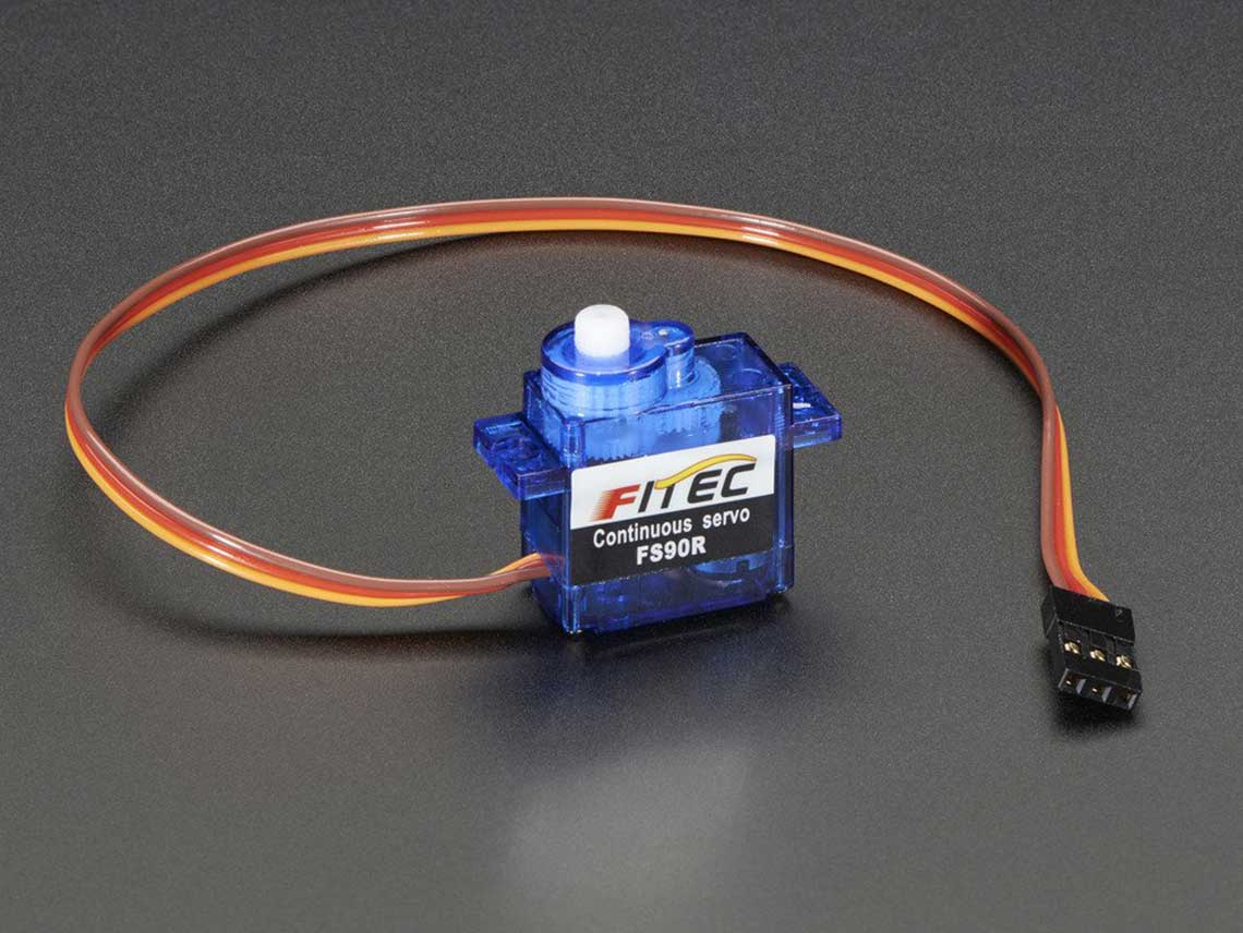 This is the sketch I used to test the continuous rotation. The settings are kind of random, it was just to test the prototype of the gear system. More details on that here.
    #include <Servo.h>

    #define TURN_TIME 500 //in millis

    Servo myservo;

    void setup() {
        myservo.attach(10);
        // Initially the servo must be stopped
        myservo.write(90);
    }

    void loop() {
        // Start turning clockwise
        myservo.write(0);
        // Go on turning for the right duration
        delay(TURN_TIME);
        // Stop turning
        myservo.write(90);

        // Wait for 2s
        delay(2000);
    }
Then the difficult part for me is to know how to operate the motor to make the main gear turn 60° every minute !
Here is how I calculate that :
    Number of teeth on the small gear (A)= 12
    Number of teeth on the main gear (B)= 60

    The Rotation ratio (R) = A/B = 12/60 = 1/5 = 0,2
    So the small gear must do 5 complete revolutions for the main one to do one revolution.
    So 1h = 5x360° on A = 1800° and so 1min = 1800/60 = 30°.
With this, I know that the small gear must turn 30° every minute.Now if I look at the datasheet of the servo, I have these information :
No load speed : 110RPM (4.8v) / 130RPM (6v)
Some more calculations :
    110 RPM = 110*360 per min. = 39 600° per 60sec. = 660° per sec. = 1/22sec per 30° = 0.04545455
    130 RPM = 130*360 per min. = 46 800° per 60sec. = 780° per sec. = 1/26sec per 30° = 0.03846154
Update June 5
LED control for hours and minutes
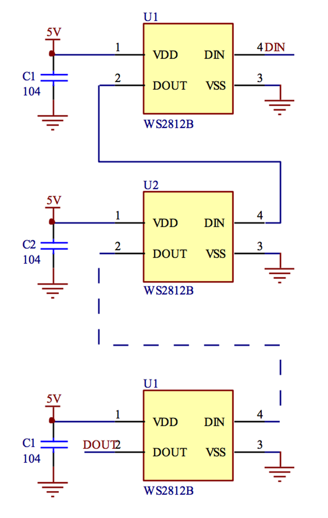
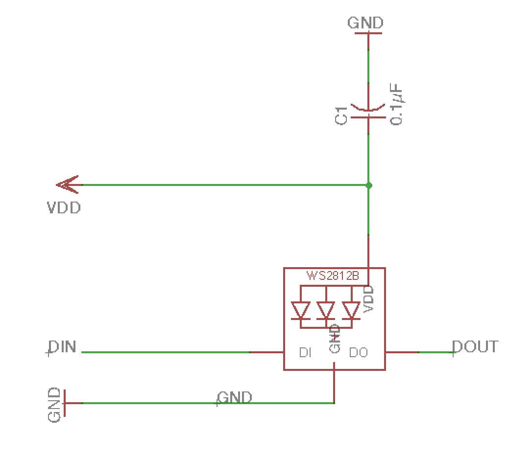
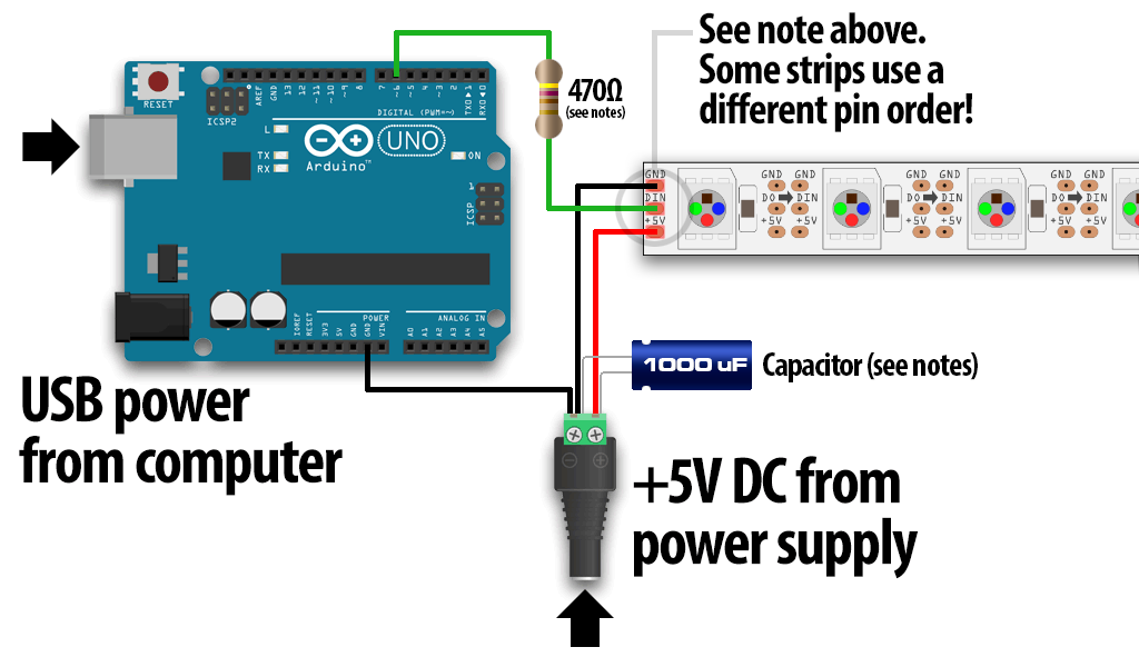
After a lot of research and a few tests, I realized that using a servo for my mechanical minutes gear system was to complex of a project for me. Also, I would be really hard to be precise and to keep good track of the time, and since I'm already pretty late schedule, I've decided to simplify things and to work only with LEDs also for the minutes. So I'll will use 60 neopixel RGB LEDs disposed in a ring pattern, to mark the minutes.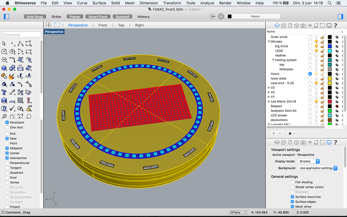 These LEDs, distributed by Adafruit are great because the come with an integrated driver chip, which allows then to be very easily chainable and also has a constant current drive so the color will be very consistent even if the voltage varies. It also supress the need for choke resistors, so the electronic design will be very minimal : I will just need to connect the output of on LED to the input of the next. The first LED of the chain will have its input connected to one pin of the microcontroller.
Then adding a 0.1 μF capacitor between + and ground is recommended for each pixel. Considering I will also use the same LEDs for the hours, here a new table of what I need for the two LED rings :
| Item | Dimensions | Quantity |
|---|---|---|
Neopixel RGB LEDs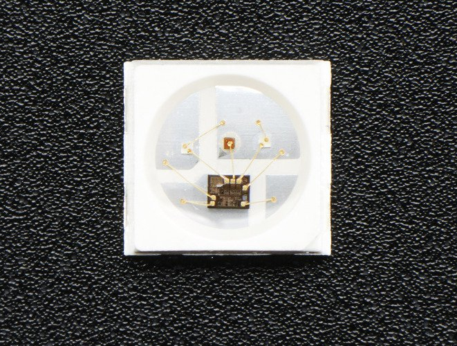 > Datasheet
|
3,5x3,5mm | 12 |
| Neopixel RGB LEDs (same ones but larger)
> Datasheet
|
5x5mm | 60 |
0.1µF capacitors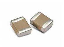
|
72 |
 I found this Instructable which will help me solder my Neopixels together because it is not as easy as it seems... I could have used Neopixel breakouts or even Neopixel strips but the first one was a bit of a cheat in my opinion and the second one not compatible with a circular layout.
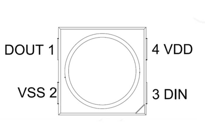
Now the fact that I'm using two different versions of the Neopixels ils a bit tricky because the 3535 and 5050 are not mounted the same way. If we look at the datasheets, the layouts are opposite :
The 5050 version :
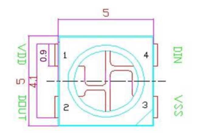
The 3535 version :
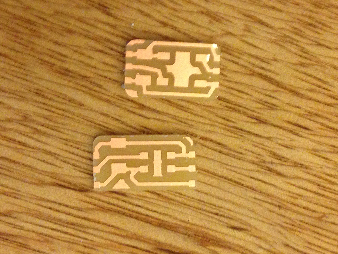
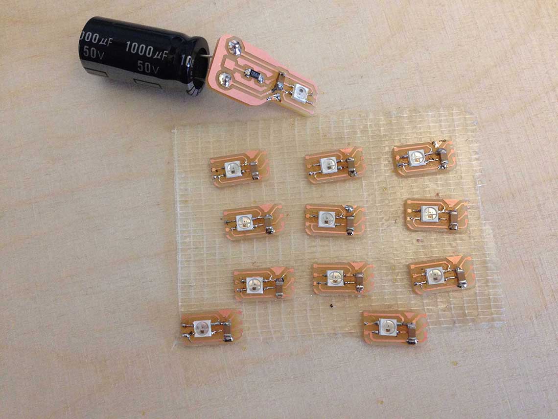
 For the hours, here is the little "pixel board" I designed :
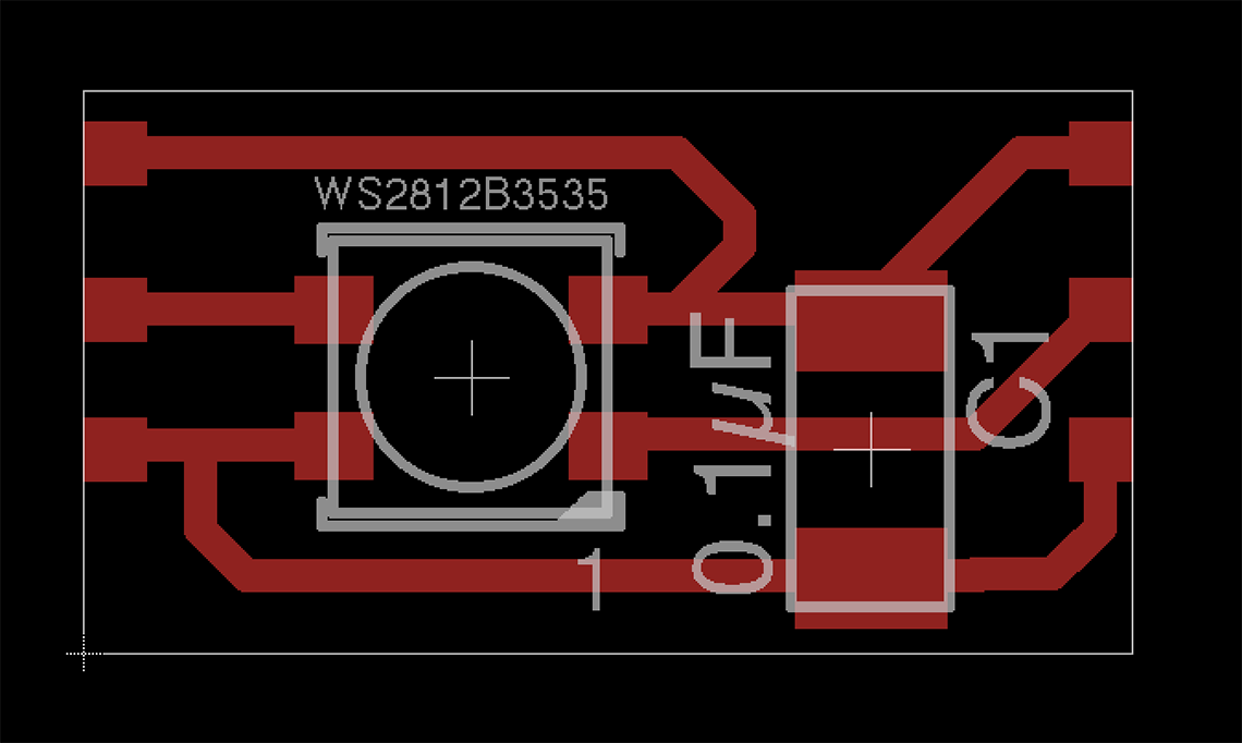 I will just have to make 12 of them place on a circle of the right diameter, that I will laser cut.
For the minutes however, it is a little more complicated because I have to make really small boards, to fit on the circle I have designed in Rhino. We can see here that there is not much space between each LED (light blue squares) :
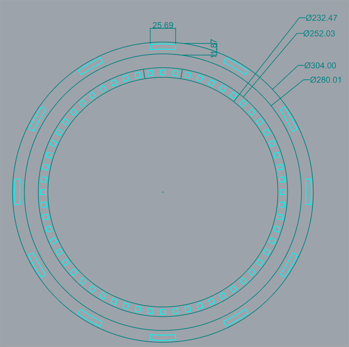 So to be sure, what I did is I copied a segment of the circle with 3 LEDs, saved it as a .dxf file and imported it in Eagle to use it as a guide (in dark blue here) :
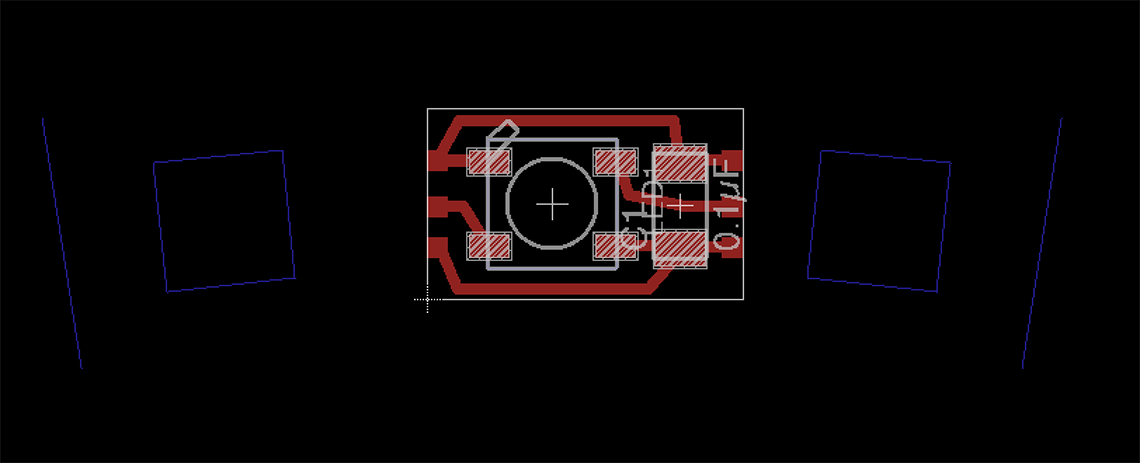 This allowed me to determine the righ dimensions for the board and to make so tests with 3 boards placed on the guides :
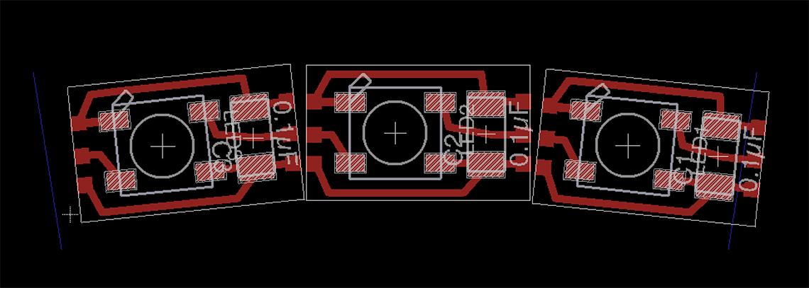 Ultimately I designed this 6 LED segment : I'll just have to mill 10 of them and attach them together. It will save me a lot of hassle soldering the boards together !
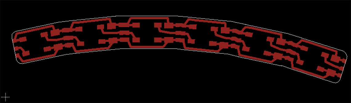
First of I milled to test boards, one for each type of LED :
 And then I soldered a 5050 Neopixel and some cables to make a simple test :
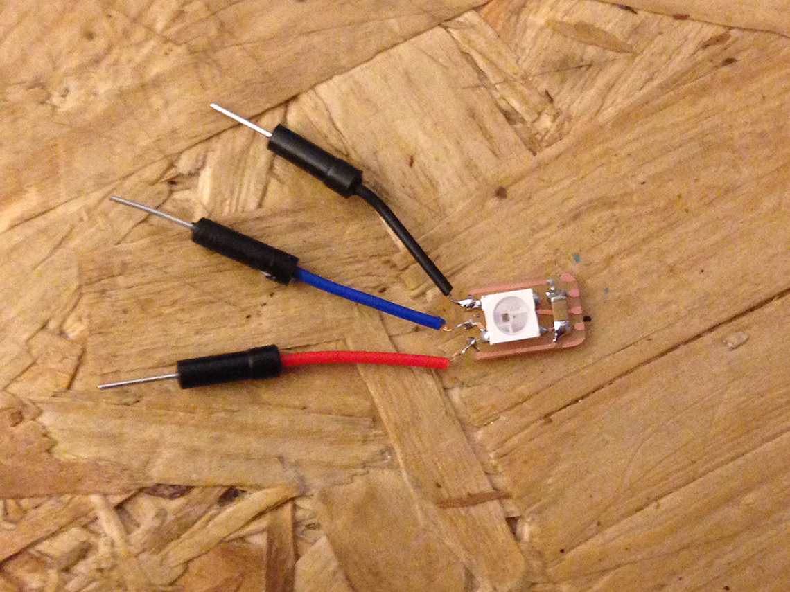 This is a piece of code I took and modified from the examples in the Neopixel library from Adafruit :
            // NeoPixel Ring simple sketch (c) 2013 Shae Erisson
            // released under the GPLv3 license to match the rest of the AdaFruit NeoPixel library

            #include
            #ifdef __AVR__
              #include
            #endif

            // Which pin on the Arduino is connected to the NeoPixels?
            // On a Trinket or Gemma we suggest changing this to 1
            #define PIN            6

            // How many NeoPixels are attached to the Arduino?
            #define NUMPIXELS      1

            // When we setup the NeoPixel library, we tell it how many pixels, and which pin to use to send signals.
            // Note that for older NeoPixel strips you might need to change the third parameter--see the strandtest
            // example for more information on possible values.
            Adafruit_NeoPixel pixels = Adafruit_NeoPixel(NUMPIXELS, PIN, NEO_GRB + NEO_KHZ800);

            int delayval = 500; // delay for half a second

            void setup() {

              pixels.begin(); // This initializes the NeoPixel library.
            }

            void loop() {

              // For a set of NeoPixels the first NeoPixel is 0, second is 1, all the way up to the count of pixels minus one.

              for(int i=0;i<NUMPIXELS;i++){

                // pixels.Color takes RGB values, from 0,0,0 up to 255,255,255
                pixels.setPixelColor(i, pixels.Color(0,0,255)); // Full blue.

                pixels.show(); // This sends the updated pixel color to the hardware.

                delay(delayval); // Delay for a period of time (in milliseconds).

                pixels.setPixelColor(i, pixels.Color(0,255,0)); // Full green.

                pixels.show(); // This sends the updated pixel color to the hardware.

                delay(delayval);

                pixels.setPixelColor(i, pixels.Color(255,0,0)); // Full red.

                pixels.show(); // This sends the updated pixel color to the hardware.
                delay(delayval);
              }
            }
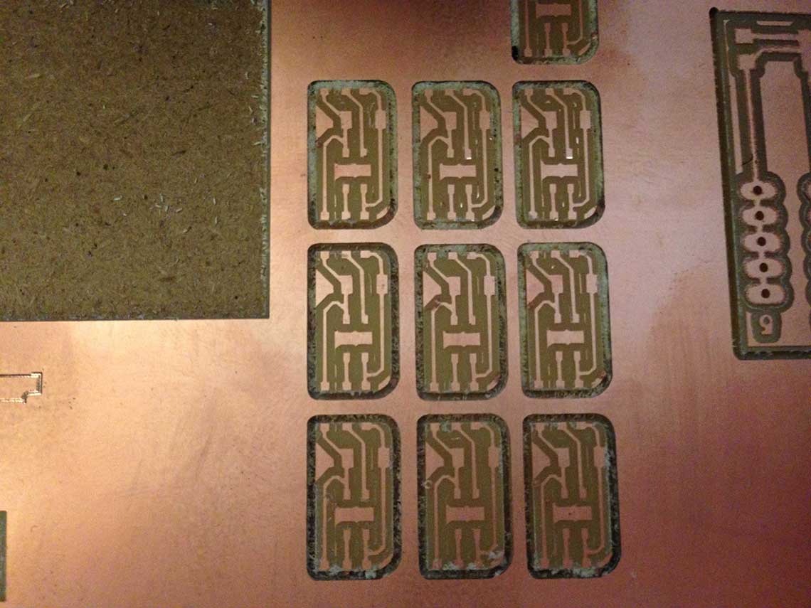
And the result :Then I milled the twelve little PCBs for the hours :
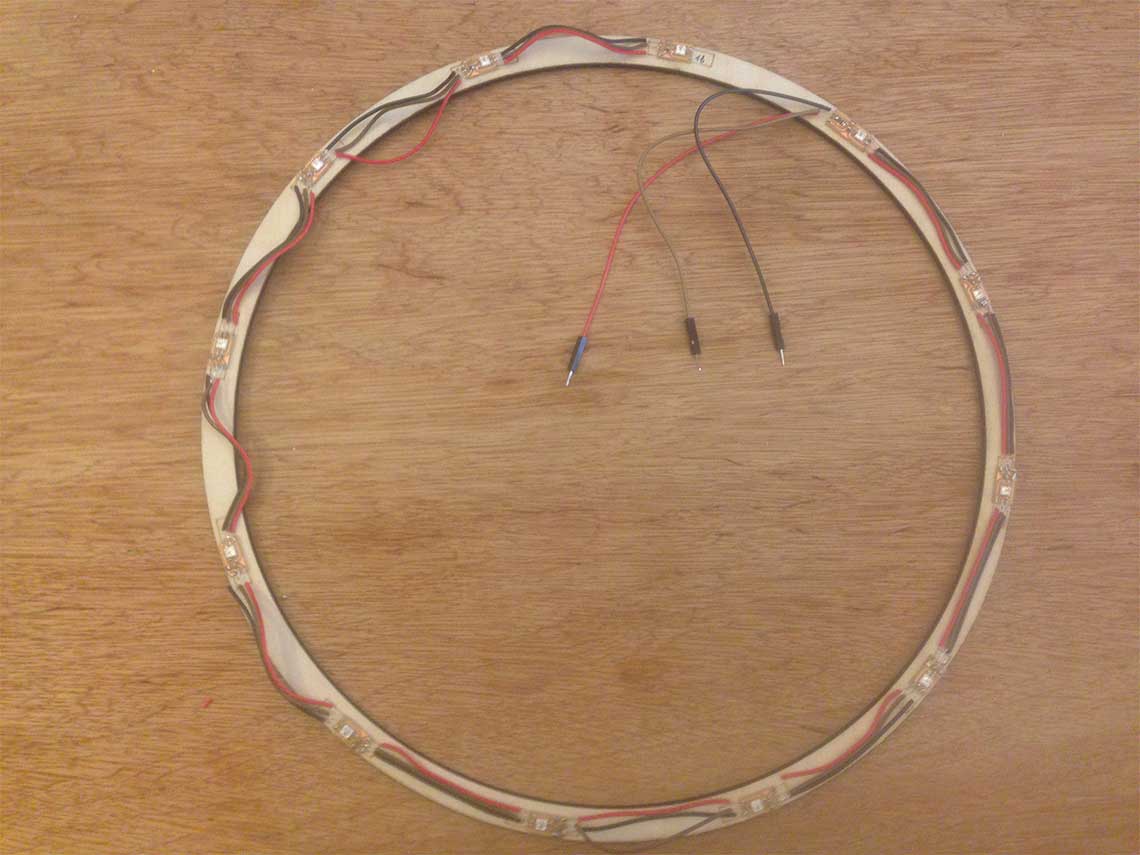
 Next step was to laser cut the rings for the hours (and also for the minutes at the same time) :
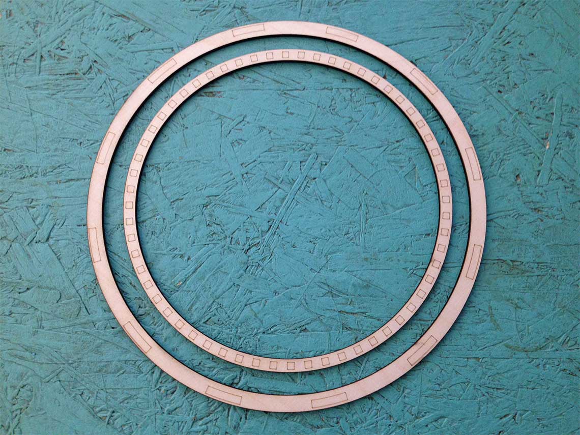 And then solder the Neopixels boards on the ring and link them with wires, which took me forever !
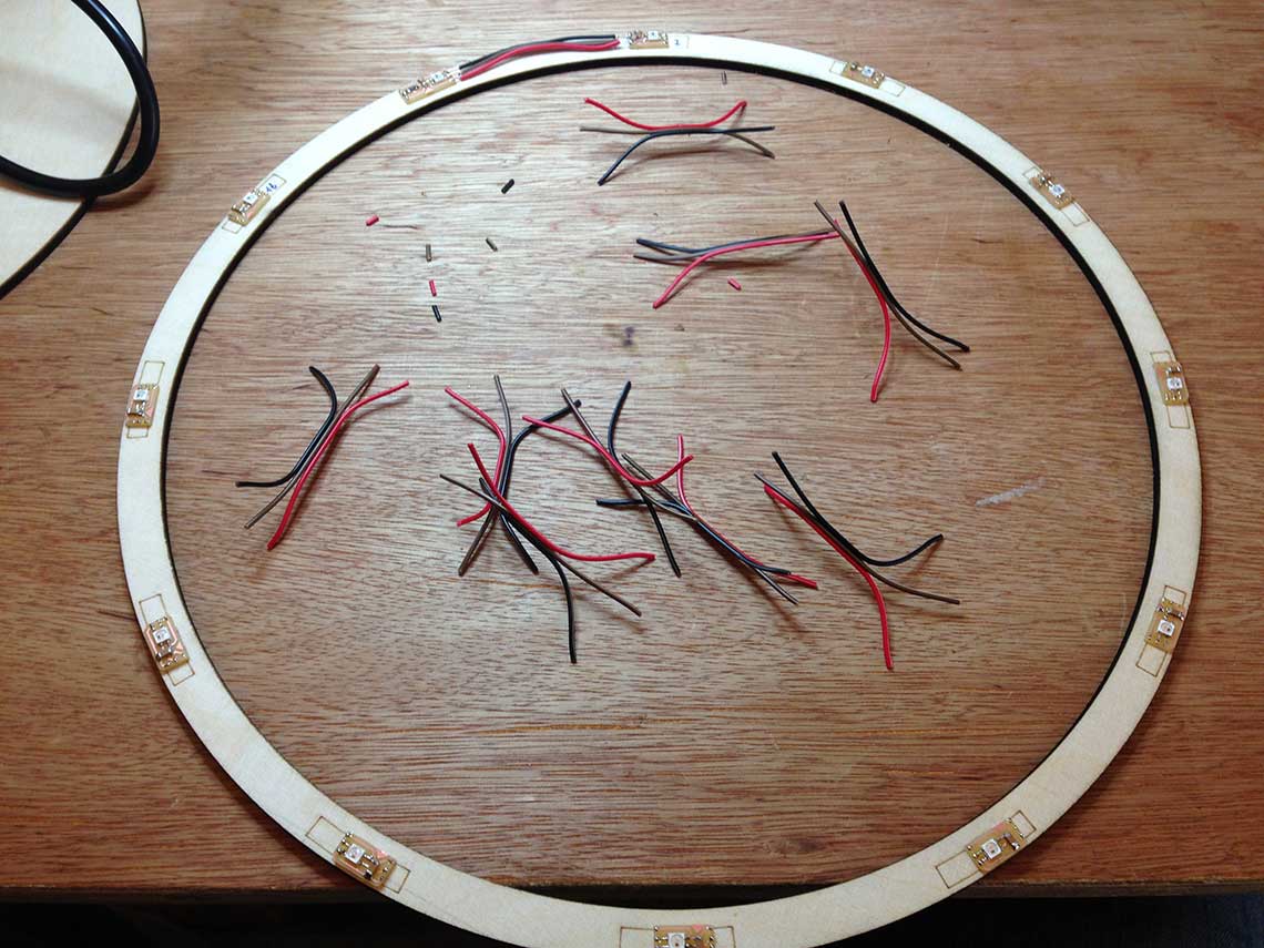
 I checked and re-checked all boards, connections and all and it seemed OK. My guess is I burned some LEDs when I soldered them : I noticed that the soldering iron we have is really hot, too hot in my opinion. I also noticed that when I connected the data output of the 1st neopixel to the input of the 3rd one instead of second, the 3rd one worked, but not the 4th. So I probably burned the 2nd AND 4th ones... Great.
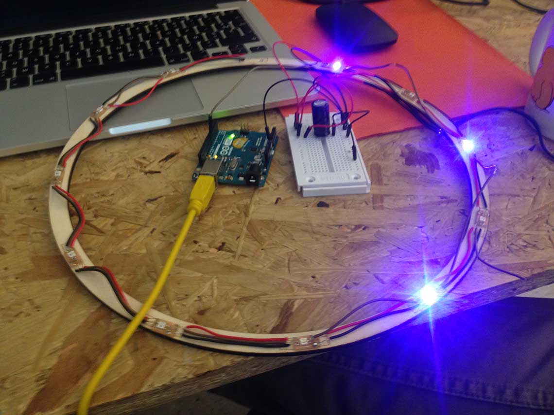 With this observation I then wanted to know if the 2nd and 4th neopixels were really burned so I removed them and tested them individually. Confirmation :
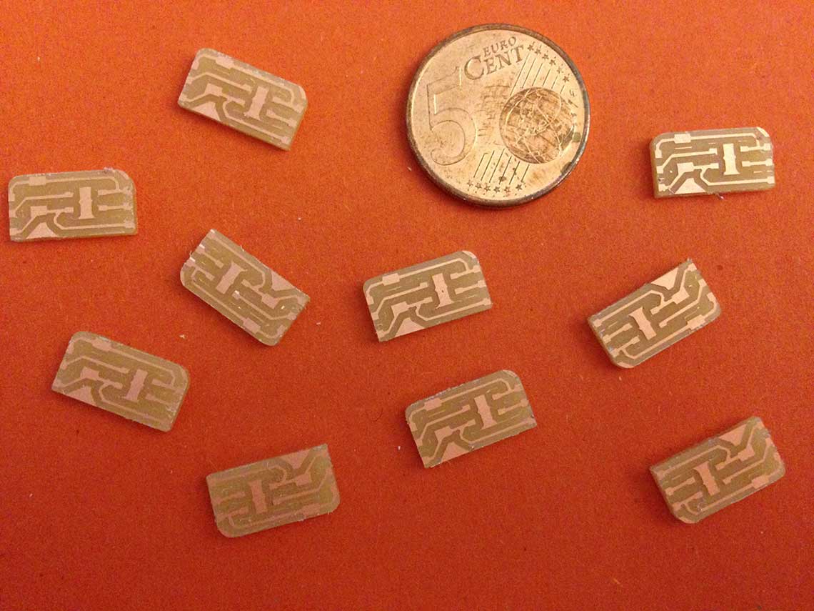
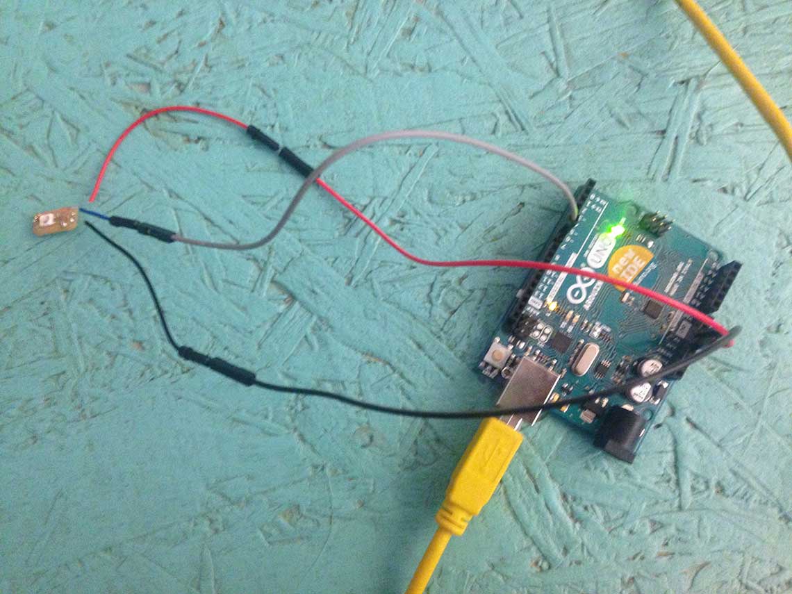 After testing all of them I had only 4 out of 12 that were working...
Just to be sure, I remilled 8 little LED boards and took great care of soldering all the wires first, then the capacitors and finally the Neopixels.
After testing all of them I had only 4 out of 12 that were working...
Just to be sure, I remilled 8 little LED boards and took great care of soldering all the wires first, then the capacitors and finally the Neopixels.And now everything works great ! Here's the version embedded in the prototype number two (even worse than number one !)
 For the minutes I added a joint to each end of the segments to make them press-fit, using Rhino :
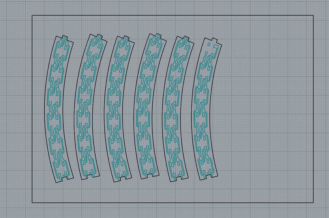 Then I imported them in Illustrator, turned them into images and generated the gcodes using Fabmodules. When milled, the result is pretty cool :
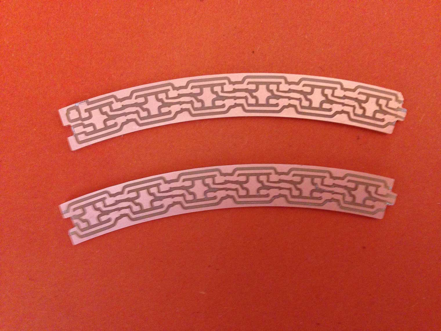 And assembled :
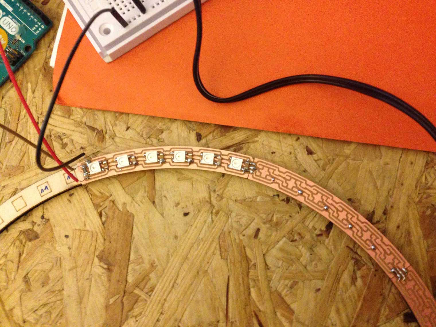
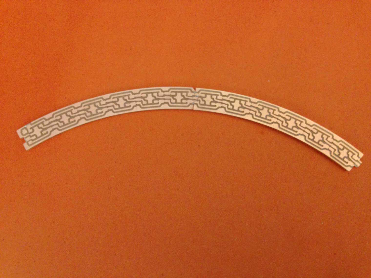 Then the hardest part was to solder the 60 Neopixels and capacitors !!
Here's a work-in-progress picture :
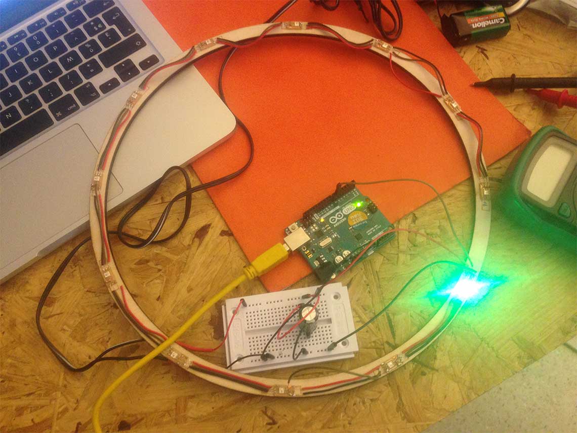
 Final result :
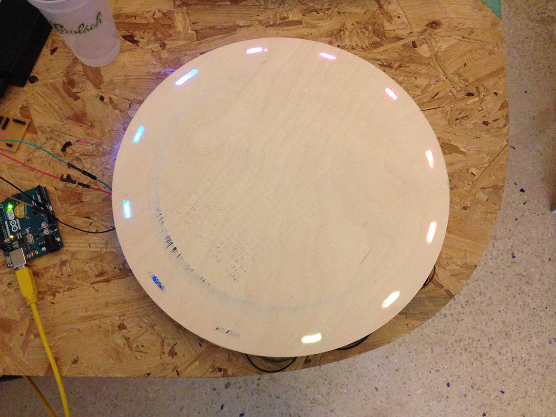
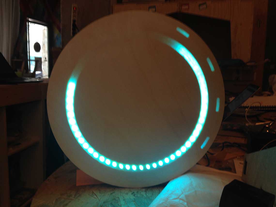
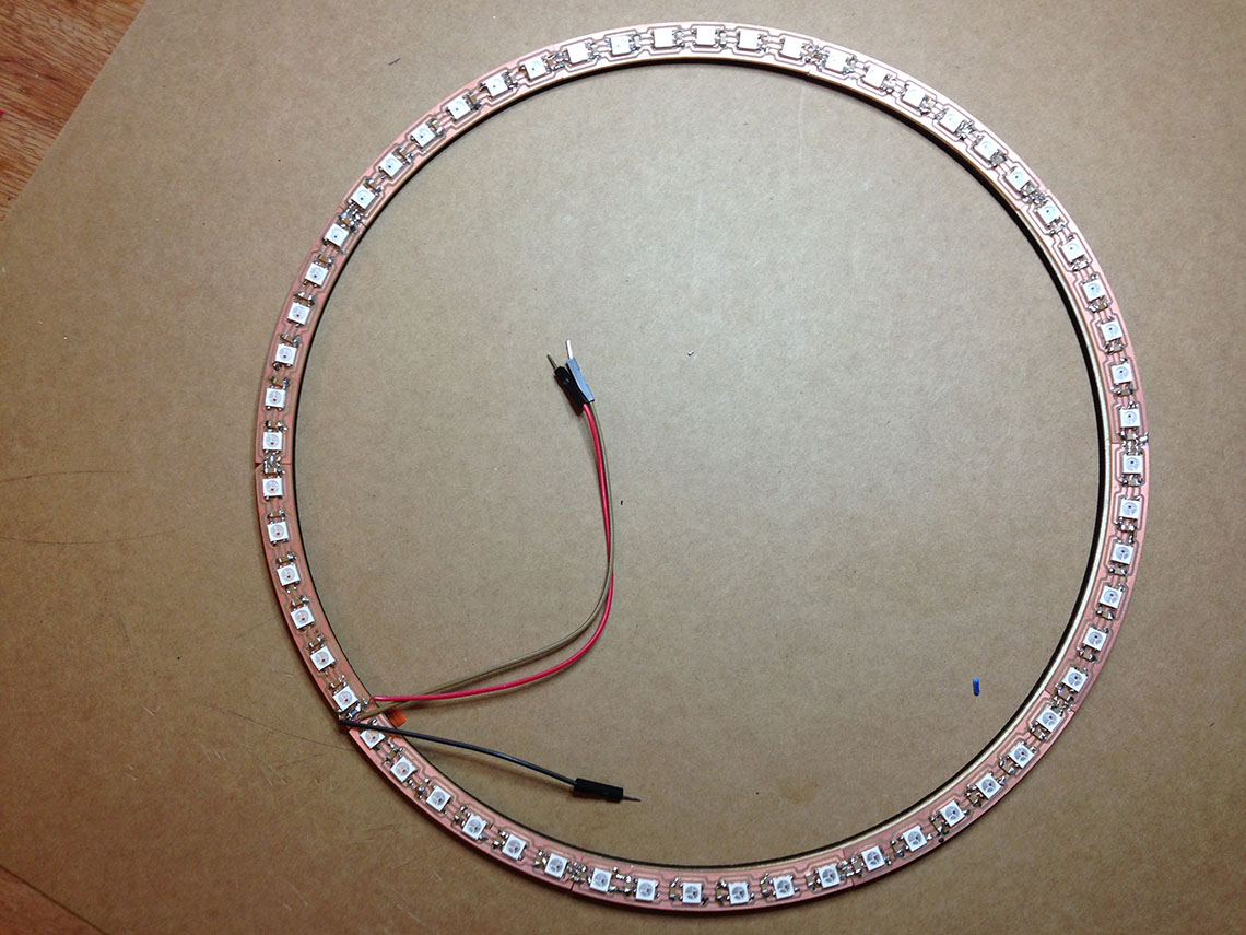 Working test :
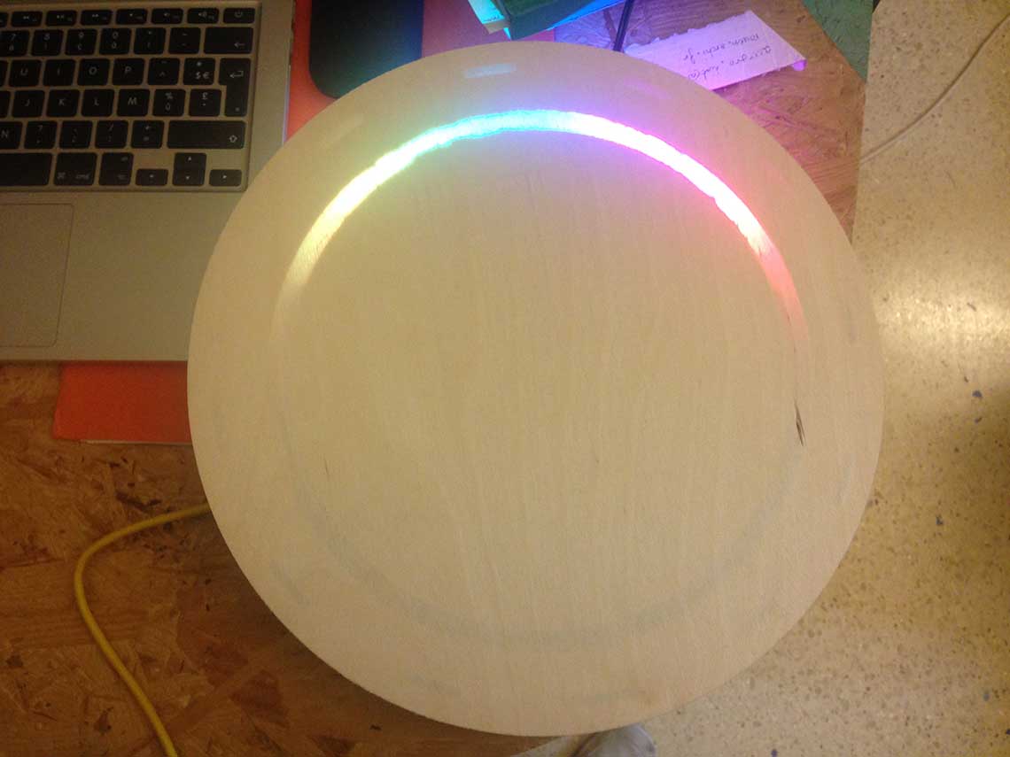
LED matrix control
As previously presented on Week 16, I bought this gorgeous 16x32 RGB LED Matrix at Adafruit.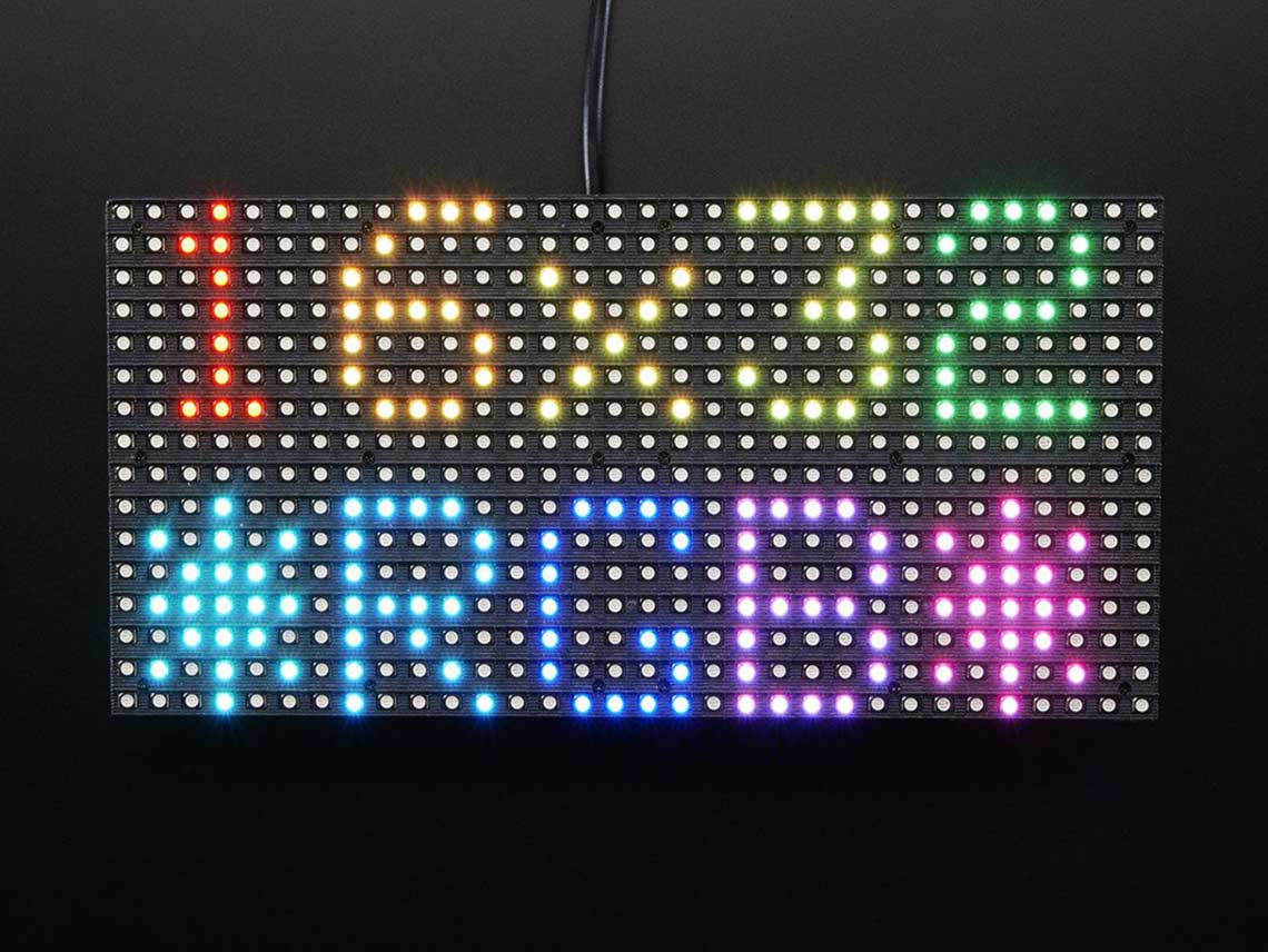 Everything is explained on how to power it, wire it to your Arduino, etc.
It comes with an Arduino Library and it is pretty well explained. I found almost everything I needed to know and this introduction to the library. And also here for more info on the GFX library which is made for drawing things a on LED matrix or on LCD screens.
Then I did a first test of the matrix using prototype clock number one and an example from the matrix library :
Pretty awesome right ?
Then I learn how to use the library and how to draw things on the matrix. My goal was to be able to draw some icons to represent the weather :
Sunny :

Partly cloudy :

Cloudy :

Rainy :

          //Byte array of bitmap of 32 x 16 px:
          img [] = {
          0x0, 0x0, 0x0, 0x0, 0x0, 0x0, 0x0, 0x0, 0x0, 0x0, 0x80, 0x0, 0x0, 0x8, 0x8,
          0x0, 0x0, 0x4, 0x90, 0x0, 0x0, 0x1, 0xc0, 0x0, 0x0, 0x2, 0x20, 0x0, 0x0, 0x16,
          0x34, 0x0, 0x0, 0x2, 0x20, 0x0, 0x0, 0x1, 0xc0, 0x0, 0x0, 0x4, 0x90, 0x0, 0x0,
          0x8, 0x8, 0x0, 0x0, 0x0, 0x80, 0x0, 0x0, 0x0, 0x0, 0x0, 0x0, 0x0, 0x0, 0x0,
          0x0, 0x0, 0x0, 0x0,
           }
Here is a test code for display alternatively all the types of icon I chose :
         #include <Adafruit_GFX.h>   // Core graphics library
         #include <RGBmatrixPanel.h> // Hardware-specific library

         #define CLK 8  // MUST be on PORTB! (Use pin 11 on Mega)
         #define LAT A3
         #define OE  9
         #define A   A0
         #define B   A1
         #define C   A2
         RGBmatrixPanel matrix(A, B, C, CLK, LAT, OE, false);
         const unsigned char PROGMEM sun[] =
         // SUN
         {
         0x0, 0x8, 0x0, 0x0, 0x0, 0x80, 0x80, 0x0, 0x0, 0x49, 0x0, 0x0, 0x0, 0x1c, 0x0,
         0x0, 0x0, 0x22, 0x0, 0x0, 0x1, 0x63, 0x40, 0x0, 0x0, 0x22, 0x0, 0x0, 0x0, 0x1c,
         0x0, 0x0, 0x0, 0x49, 0x0, 0x0, 0x0, 0x80, 0x80, 0x0, 0x0, 0x8, 0x0, 0x0, 0x0,
         0x0, 0x0, 0x0, 0x0, 0x0, 0x0, 0x0, 0x0, 0x0, 0x0, 0x0, 0x0, 0x0, 0x0, 0x0,
         0x0, 0x0, 0x0, 0x0,
         };
         const unsigned char PROGMEM suncloud[] =
         // SUN AND CLOUDS
         {
         0x0, 0x8, 0x0, 0x0, 0x0, 0x80, 0xf0, 0x0, 0x0, 0x49, 0xf8, 0x0, 0x0, 0x1d, 0xfc,
         0x0, 0x0, 0x23, 0xfe, 0x0, 0x1, 0x67, 0xff, 0x0, 0x0, 0x27, 0xff, 0x0, 0x0, 0x1f,
         0xff, 0x80, 0x0, 0x7f, 0xff, 0x80, 0x0, 0xff, 0xff, 0x80, 0x1, 0xff, 0xff, 0x80, 0x1,
         0xff, 0xff, 0x0, 0x0, 0x0, 0x0, 0x0, 0x0, 0x0, 0x0, 0x0, 0x0, 0x0, 0x0, 0x0,
         0x0, 0x0, 0x0, 0x0,
         };
         const unsigned char PROGMEM rain[] =
         // RAIN
         {
         0x0, 0x0, 0x0, 0x0, 0x0, 0x0, 0x70, 0x0, 0x0, 0x0, 0xf8, 0x0, 0x0, 0x1, 0xfc,
         0x0, 0x0, 0x3, 0xfe, 0x0, 0x0, 0x7, 0xff, 0x0, 0x0, 0x7, 0xff, 0x0, 0x0, 0x1f,
         0xff, 0x80, 0x0, 0x3f, 0xff, 0x80, 0x0, 0xff, 0xff, 0x80, 0x1, 0xff, 0xff, 0x80, 0x1,
         0xff, 0xff, 0x0, 0x0, 0x22, 0x48, 0x0, 0x0, 0x66, 0xd8, 0x0, 0x0, 0x4c, 0x90, 0x0,
         0x0, 0x8, 0x0, 0x0,
          };
         const unsigned char PROGMEM cloud[] =
         // CLOUD
         {
         0x0, 0x0, 0x0, 0x0, 0x0, 0x0, 0x70, 0x0, 0x0, 0x0, 0xf8, 0x0, 0x0, 0x1, 0xfc,
         0x0, 0x0, 0x3, 0xfe, 0x0, 0x0, 0x7, 0xff, 0x0, 0x0, 0x7, 0xff, 0x0, 0x0, 0x1f,
         0xff, 0x80, 0x0, 0x3f, 0xff, 0x80, 0x0, 0xff, 0xff, 0x80, 0x1, 0xff, 0xff, 0x80, 0x1,
         0xff, 0xff, 0x0, 0x0, 0x0, 0x0, 0x0, 0x0, 0x0, 0x0, 0x0, 0x0, 0x0, 0x0, 0x0,
         0x0, 0x0, 0x0, 0x0,
          };
         void setup()
         {
         matrix.begin();
         }
         void loop() {
           // draw a sun
           matrix.drawBitmap(0, 0,  sun, 32, 16, matrix.Color333(4,7,0));
           delay (2000);
           matrix.drawBitmap(0, 0,  cloud, 32, 16, matrix.Color333(5,7,7));
           delay (2000);
           // clear matrix
           matrix.fillScreen(0);
           delay (0);
           matrix.drawBitmap(0, 0,  rain, 32, 16, matrix.Color333(0,4,7));
           matrix.drawBitmap(0, 0,  cloud, 32, 16, matrix.Color333(5,7,7));
           delay (2000);
           // clear matrix
           matrix.fillScreen(0);
           delay (0);
           matrix.drawBitmap(0, 0,  cloud, 32, 16, matrix.Color333(5,7,7));
           delay (2000);
           matrix.fillScreen(0);
           delay (0);
           //write the temperature
           matrix.setCursor(8, 4);
           matrix.setTextSize(1);
           matrix.setTextColor(matrix.Color333(4,7,0));
           matrix.print('2');
           matrix.print('2');
           matrix.drawCircle(21, 5, 1, matrix.Color333(4,7,0));
           delay (2000);
           matrix.fillScreen(0);
           delay (0);
          }
And the demo :WiFi Communication with weather API and NTP
The first thing I did was to configure the API I will use for the weather information, which is Forecast.io. I modified the .php script which is provided on this useful tutorial on how to create a weather display using the ESP8266. This script allows me to get the major data I want to display on my clock such as the current temperature and icon, the temperature for tomorrow and the icon, and I also added a call to get the server's time and date, which I found easier than to use a NTP server :
        <html><body>
        <?php
        include('lib/forecast.io.php');
        $param = $_GET[param];
        $apiKeyParam = "541288a68a7158ad6065fe8c0102123e";
        $latParam = "48.868438";
        $lonParam = "2.348573";
        $units = 'auto';
        $lang = 'en';

        if($param != "MINUTE" && $param != "HOUR" && $param != "DATE" ) {
          $forecast = new ForecastIO($apiKeyParam, $units, $lang);
          $condition = $forecast->getCurrentConditions($latParam, $lonParam);
          $conditions_week = $forecast->getForecastWeek($latParam, $lonParam);
        }

      switch($param) {
        case "DATE":
          echo date('D')." ".date('j')." ".date('F');
          break;
        case "HOUR":
          echo date('h');
          break;
        case "MINUTE":
          echo date('i');
          break;
        case "CURRENT_TEMP":
          echo round($condition->getTemperature());
          break;
        case "CURRENT_ICON":
          echo $condition->getIcon();
          break;
        case "MAX_TEMP_TOMORROW":
          echo "MAX_TEMP_TOMORROW=" . round($conditions_week[1]->getMaxTemperature());
          //echo round($conditions_week[1]->getMaxTemperature());
          break;
        case "ICON_TOMORROW":
          echo $conditions_week[1]->getIcon();
          break;
        default:
          echo "error";
          break;
      }
        ?>
        </body>
        </html>
The nice thing with this is that I won't have to parse the data because the .php does that for me : I just have to request the right parameter, and I only get the value. A simple example of that in a web browser :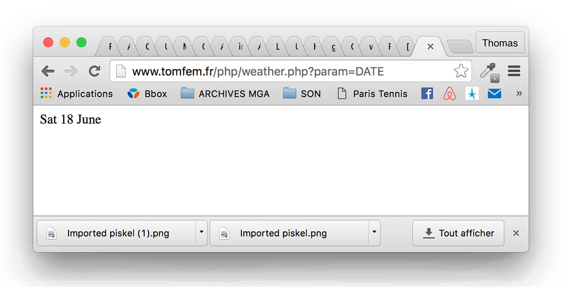 So I just have to change the param in the URL to get the right information. From this I was able to right the part of the Arduino sketch which calls for the params :
    #include <ESP8266WiFi.h>
    #include <SoftwareSerial.h>
    #include <SPI.h>
    const char* ssid     = "*******";
    const char* password = "*******";
    const char* host = "www.tomfem.fr";
    byte current_temp;
    byte current_icon;
    byte date;
    byte hour, last_hour;
    byte minute, last_minute;
    void setup() {
    Serial.begin(115200);
    delay(100);

    // We start by connecting to a WiFi network

    Serial.println();
    Serial.println();
    Serial.print("Connecting to ");
    Serial.println(ssid);

    WiFi.begin(ssid, password);

    while (WiFi.status() != WL_CONNECTED) {
      delay(500);
      Serial.print(".");
    }

    Serial.println("");
    Serial.println("WiFi connected");
    Serial.println("IP address: ");
    Serial.println(WiFi.localIP());
  }

  int value = 0;

  void loop() {
    delay(5000);
    ++value;

    Serial.print("connecting to ");
    Serial.println(host);

    // Use WiFiClient class to create TCP connections
    WiFiClient client;
    const int httpPort = 80;
    if (!client.connect(host, httpPort)) {
      Serial.println("connection failed");
      return;
    }
    ///////////// Request for the date //////////////
    String url = "/php/weather.php?param=DATE";
    Serial.print("Requesting URL: ");
    Serial.println(url);
    // This will send the request to the server
    client.print(String("GET ") + url + " HTTP/1.1\r\n" +
                 "Host: " + host + "\r\n" +
                 "Connection: close\r\n\r\n");
    delay(2000);
    // Read all the lines of the reply from server and print them to Serial
    while(client.available()){
      String line = client.readStringUntil('\r');
      Serial.print(line);
      hour = line.toInt();
    }
    ///////////// Request for the hour //////////////
    url = "/php/weather.php?param=HOUR";
    Serial.print("Requesting URL: ");
    Serial.println(url);
    // This will send the request to the server
    client.print(String("GET ") + url + " HTTP/1.1\r\n" +
                 "Host: " + host + "\r\n" +
                 "Connection: close\r\n\r\n");
    delay(2000);
    // Read all the lines of the reply from server and print them to Serial
    while(client.available()){
      String line = client.readStringUntil('\r');
      Serial.print(line);
      hour = line.toInt();
    }

    ///////////// Request for the minutes //////////////
    url = "/php/weather.php?param=MINUTE";
    Serial.print("Requesting URL: ");
    Serial.println(url);
    // This will send the request to the server
    client.print(String("GET ") + url + " HTTP/1.1\r\n" +
                 "Host: " + host + "\r\n" +
                 "Connection: close\r\n\r\n");
    delay(2000);
    // Read all the lines of the reply from server and print them to Serial
    while(client.available()){
      String line = client.readStringUntil('\r');
      Serial.print(line);
      minute = line.toInt();
    }
    ///////////// Request for the seconds //////////////
    url = "/php/weather.php?param=SECOND";
    Serial.print("Requesting URL: ");
    Serial.println(url);
    // This will send the request to the server
    client.print(String("GET ") + url + " HTTP/1.1\r\n" +
                 "Host: " + host + "\r\n" +
                 "Connection: close\r\n\r\n");
    delay(2000);
    // Read all the lines of the reply from server and print them to Serial
    while(client.available()){
      String line = client.readStringUntil('\r');
      Serial.print(line);
      minute = line.toInt();
    }
    ///////////// Request for the current temperature //////////////
    url = "/php/weather.php?param=CURRENT_TEMP";
    Serial.print("Requesting URL: ");
    Serial.println(url);
    // This will send the request to the server
    client.print(String("GET ") + url + " HTTP/1.1\r\n" +
                 "Host: " + host + "\r\n" +
                 "Connection: close\r\n\r\n");
    delay(2000);

    // Read all the lines of the reply from server and print them to Serial
    while(client.available()){
      String line = client.readStringUntil('\r');
      Serial.print(line);
      current_temp = line.toInt();
    }
    ///////////// Request for the current icon //////////////
    url = "/php/weather.php?param=CURRENT_ICON";
    Serial.print("Requesting URL: ");
    Serial.println(url);
    // This will send the request to the server
    client.print(String("GET ") + url + " HTTP/1.1\r\n" +
                 "Host: " + host + "\r\n" +
                 "Connection: close\r\n\r\n");
    delay(2000);
    // Read all the lines of the reply from server and print them to Serial
    while(client.available()){
      String line = client.readStringUntil('\r');
      Serial.print(line);
      current_temp = line.toInt();
    }
    Serial.println();
    Serial.println("closing connection");
With the ESP8266 Huzzah board that I bought, I can directly load Arduino sketches using a FTDI cable. This process is explained here.Power distribution
Power distribution for my clock is an important subject, especially because I am using very energy-consuming components : the Neopixels and the LED Matrix.According to the information from Adafruit, le LED Matrix needs at least 2 Amperes to work, and each Neopixel can draw between 20 and 60mA. As a rule of thumb they usually use the 20mA value.
So I would need between 2+(72x0.02) and 2+(72x0.06), or 3.44A and 6,32A. Given that I will never have all LEDs lit (meaning the Neopixels AND the matrix), I will go with a 5V and 5A power supply which will allow me to power everything. Anyway I did not find a higher current supply than 5Amps, for a 5V tension...
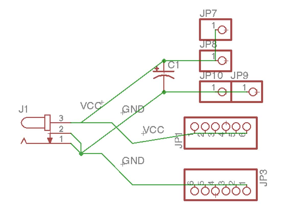
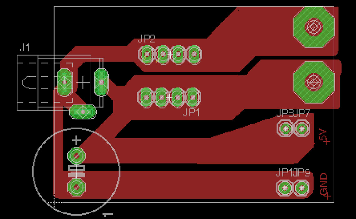
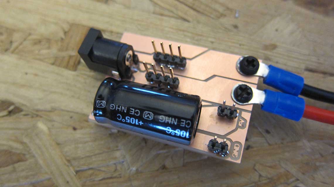
For the power distribution between the different devices that I use, I designed this board :