Specific material and softwares used during this assignment
- Material :
- 1 flat mill 6mm
- 1 flat mill 8mm
- 1 V mill with an angle of 60°
- 2 board of birch, 1000mm per 600mm
- CNC Router High-Z
- Wood glue
- several screws
- electric screwdriver
- Sander
- Software :
- Fusion360
- WinPC-NC
Design for the Tri-force shelf
It was clear for me that I was doing a shelf for this assignment and with the new Zelda in the wild, the choice was easy :)
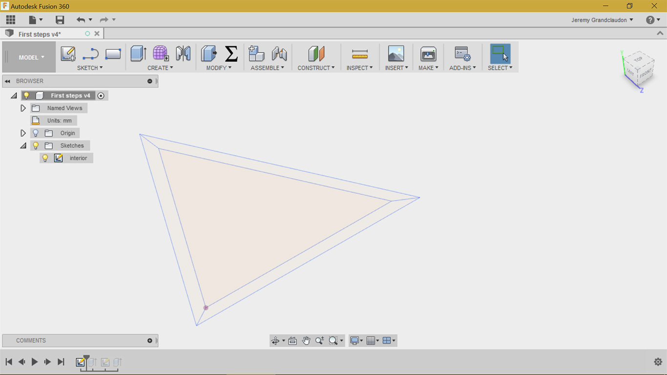
With this idea in mind, I have then attacked the sketch in Fusion360 as you can see in the images below :
I have sketch a triangle with 150mm for each side and 60°
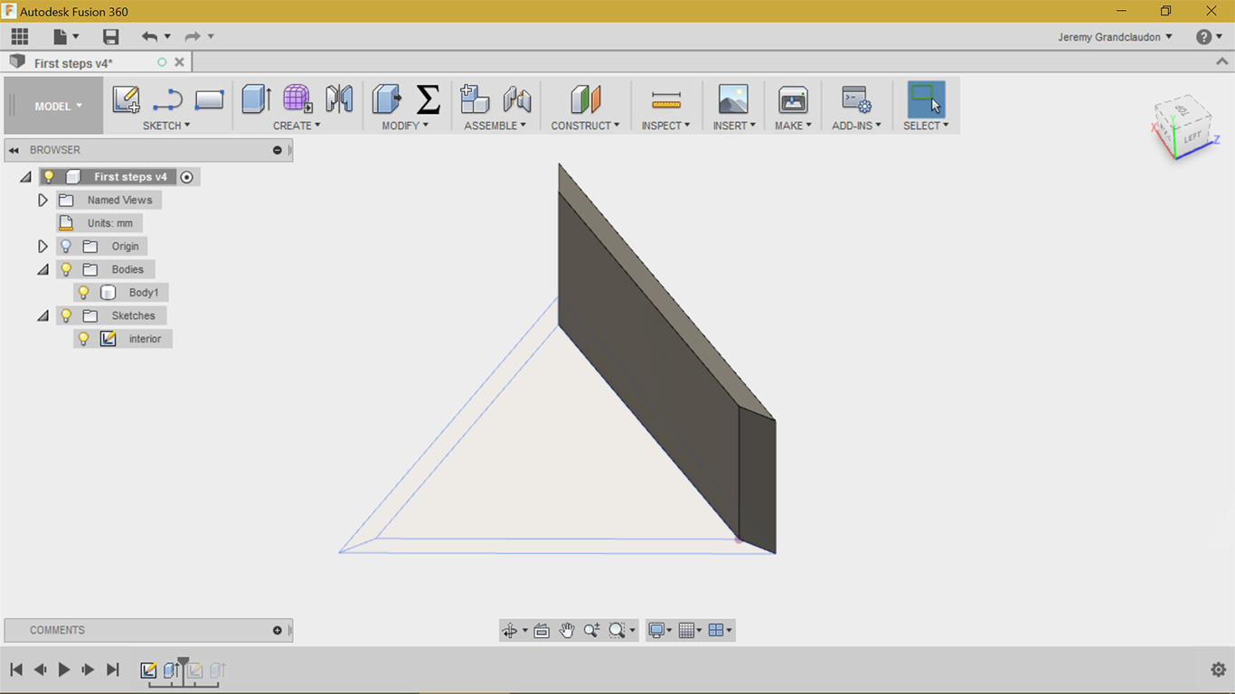
I have then extrude one face of my triangle, no need to do more for the milling as the 3 sides are identical
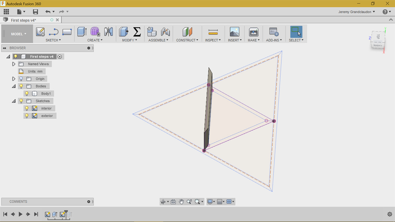
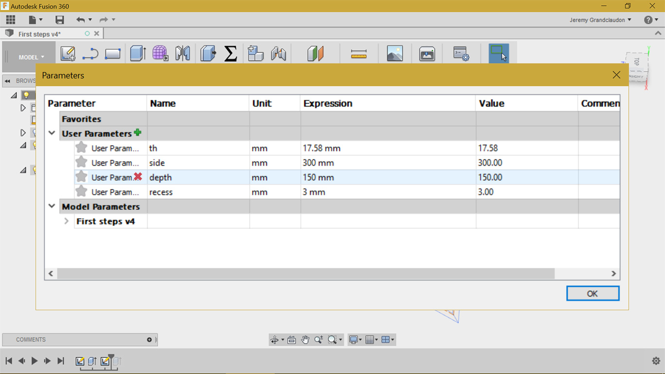
I need now a bigger triangle to finish my shelf. It's parametric so a simple offset and the exterior is done
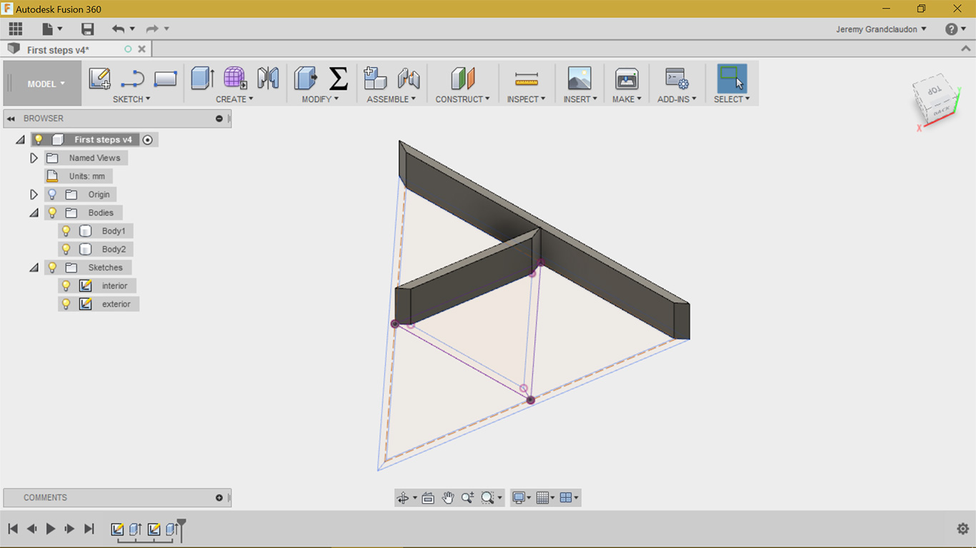
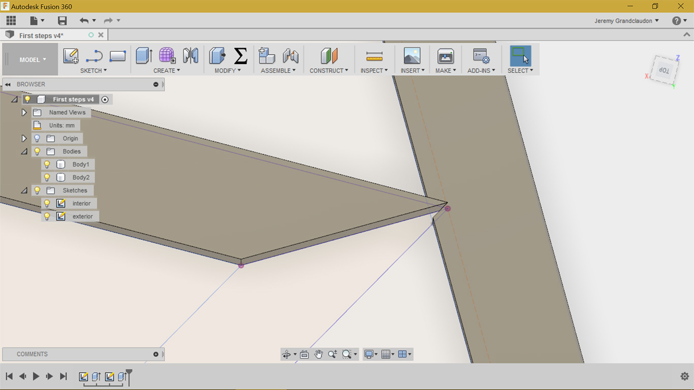
Again, no need than one extrude. I have just cut a path with a 60° angle so the small triangle will slide in the big one
You can see the cut for the small triangle here
Almost everything is parametric as you can see
My design is ready, I have now to prepare it for the CNC.
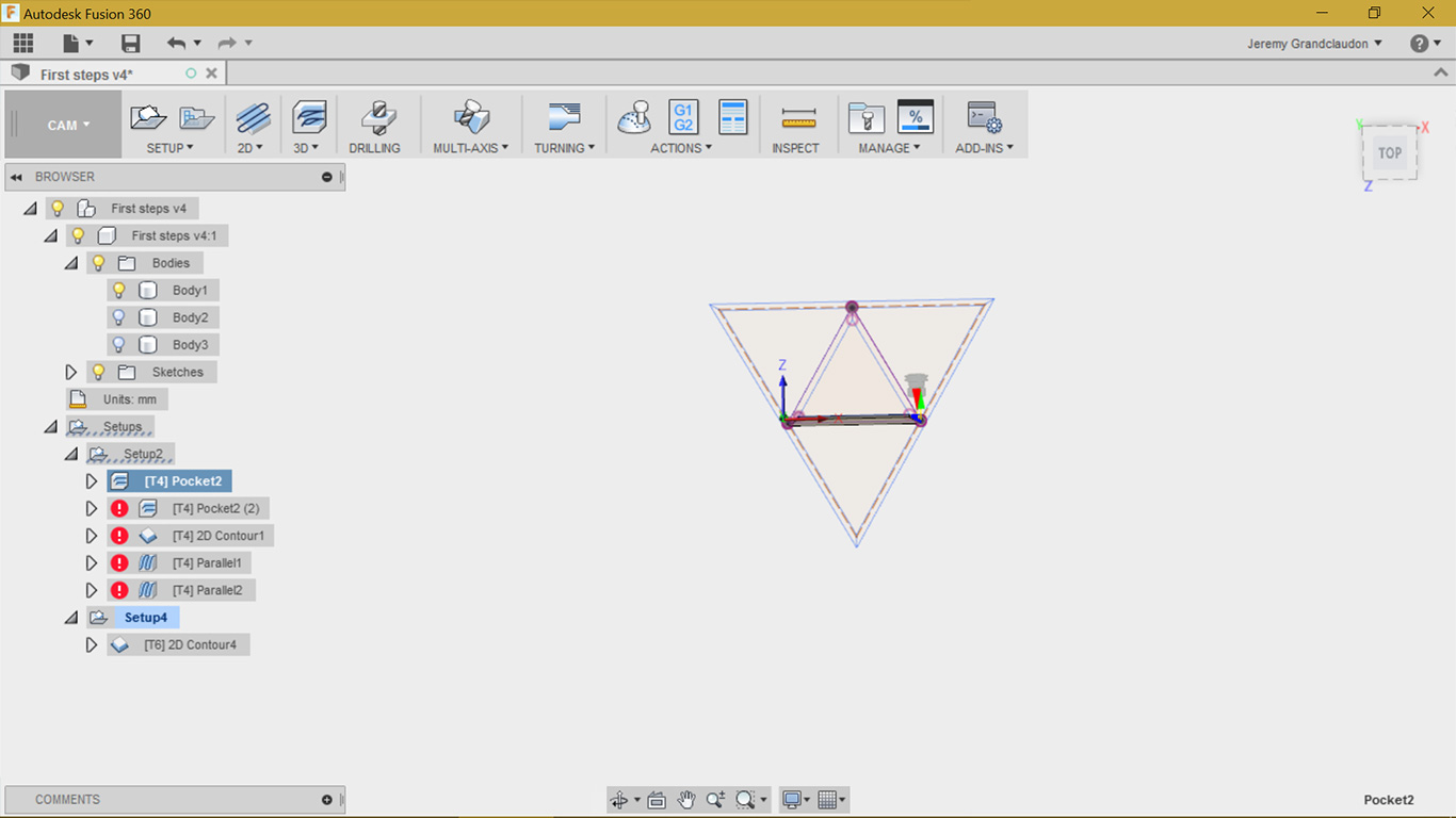
We have to access now the CAM tab, where we can establish the different paths and configure my tools
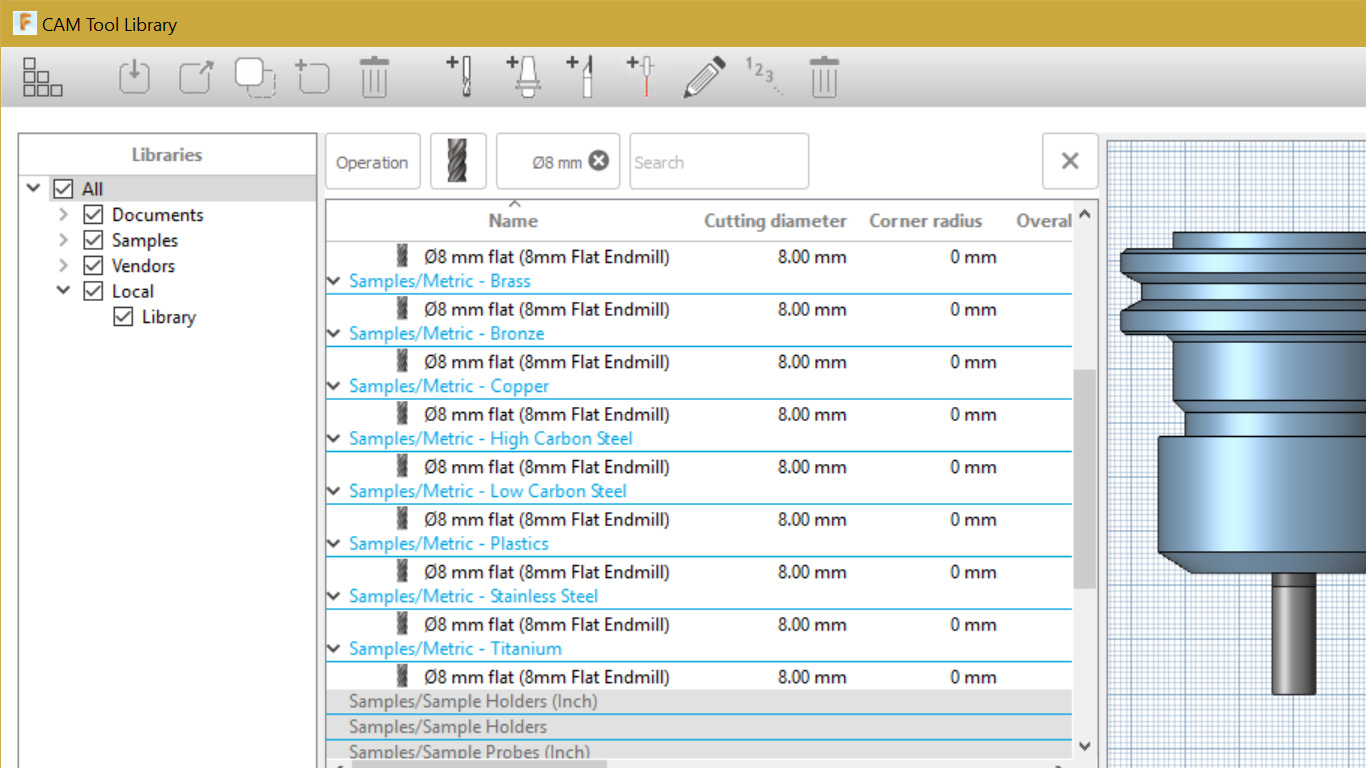
First thing first, I will select or create a tool to equip my virtual CNC in fusion. Here you can see my flat mill of 8mm. You can access it via the manage tab on top of the interface. You have then access to a wide variety of tools to calibrate your simulatiion.
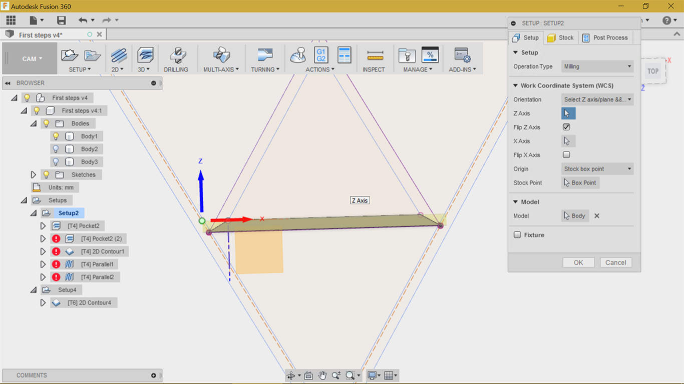
I'm now happy with my tool, I will now begin with the first path for my smaller triangle. I will need 3 path for them. Two for each sides and one for the contour. I create then my setup, this is the way to tell to fusion the global object and the board configuration where I will mill into. The setup tab is where you will choose your type of operation, here milling, you orientation, your point of origin and where is your Z axis (really important! :) )
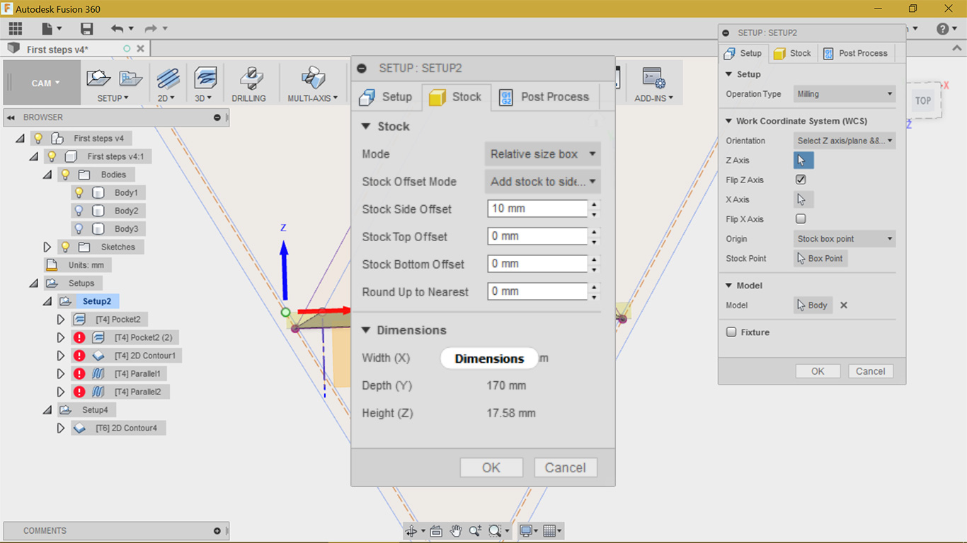
The stock tab is where your define your wood board and check your dimension. I have left alone the post process tab and only change the name of the future .nc file
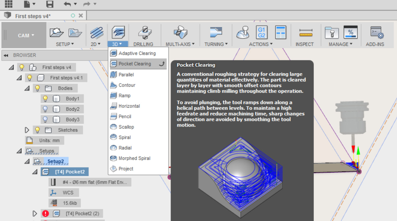
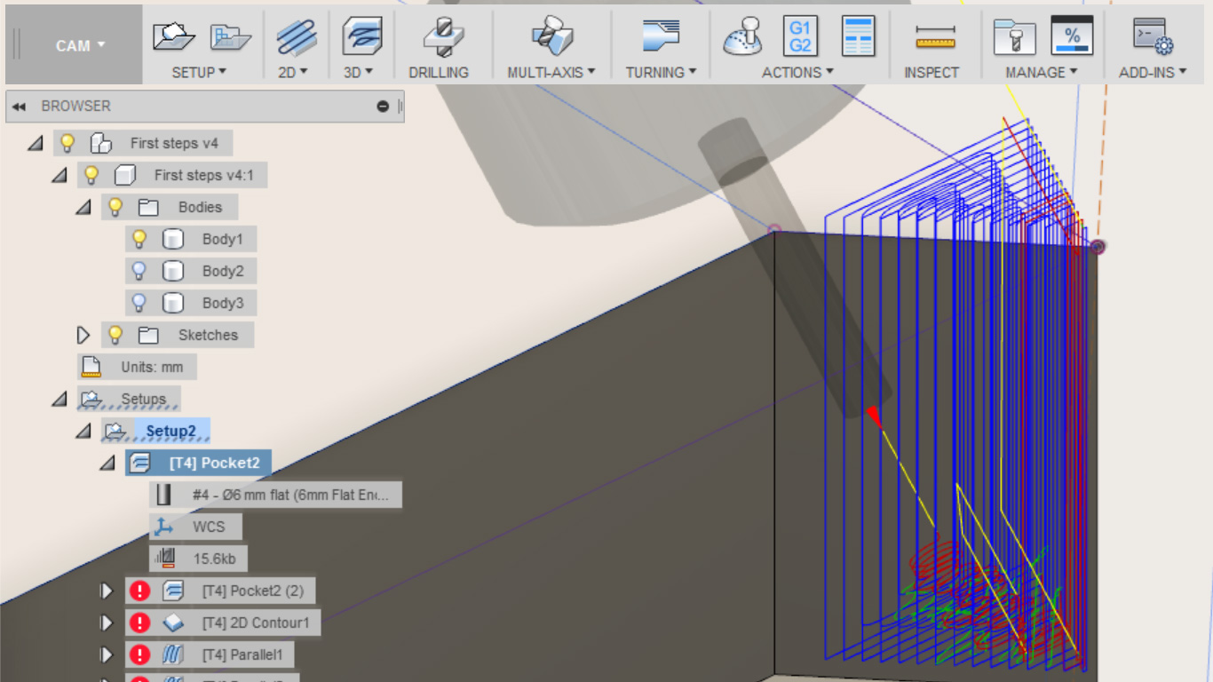
For the two clearings on the side, I will use the '3d pocket clearing'. It's suit well my need as I want to remove quickly a large quantity of material
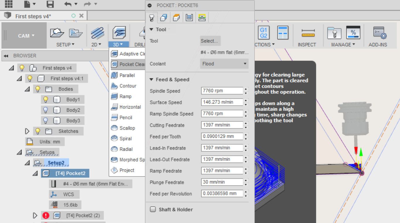
You have several tabs for this selection. The first one is the tool tab. I have only selected my tool and left the rest alone as It will be configure later on the CNC software itself.
The geometry tab allows you to change many things already defined in the setup and overide them. Be careful with it!
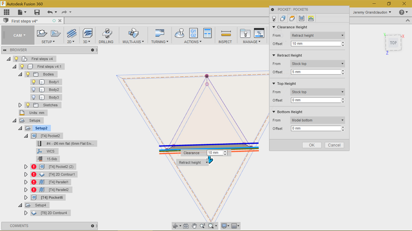
I didn't touch to the Heigh tab, not needed in my design, same for the passes and linking tab
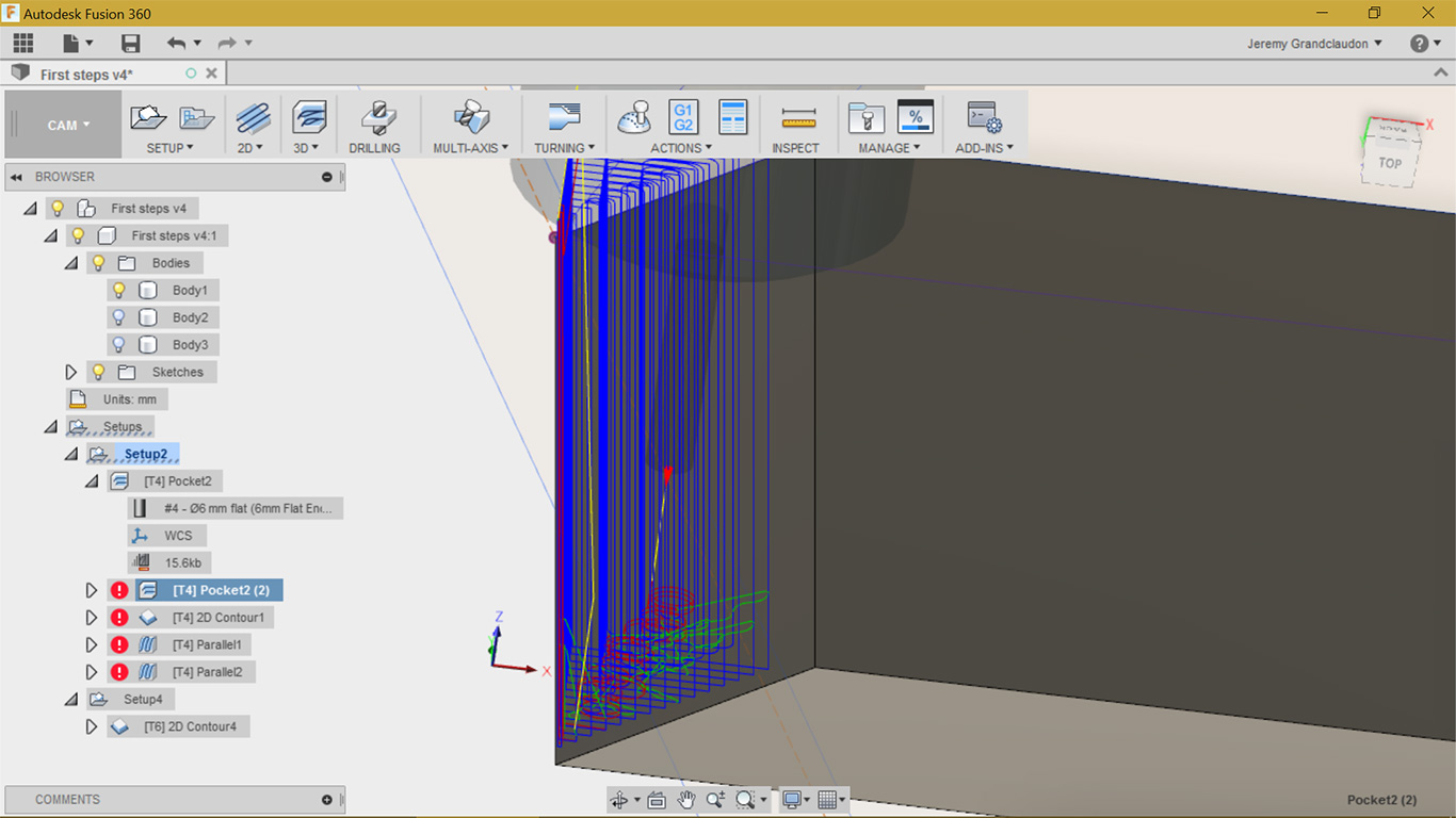
You can see the path followed by the tool, and it's seems fine so far
The other side is the same except the origin and position of the tool
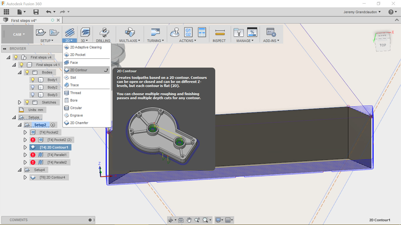
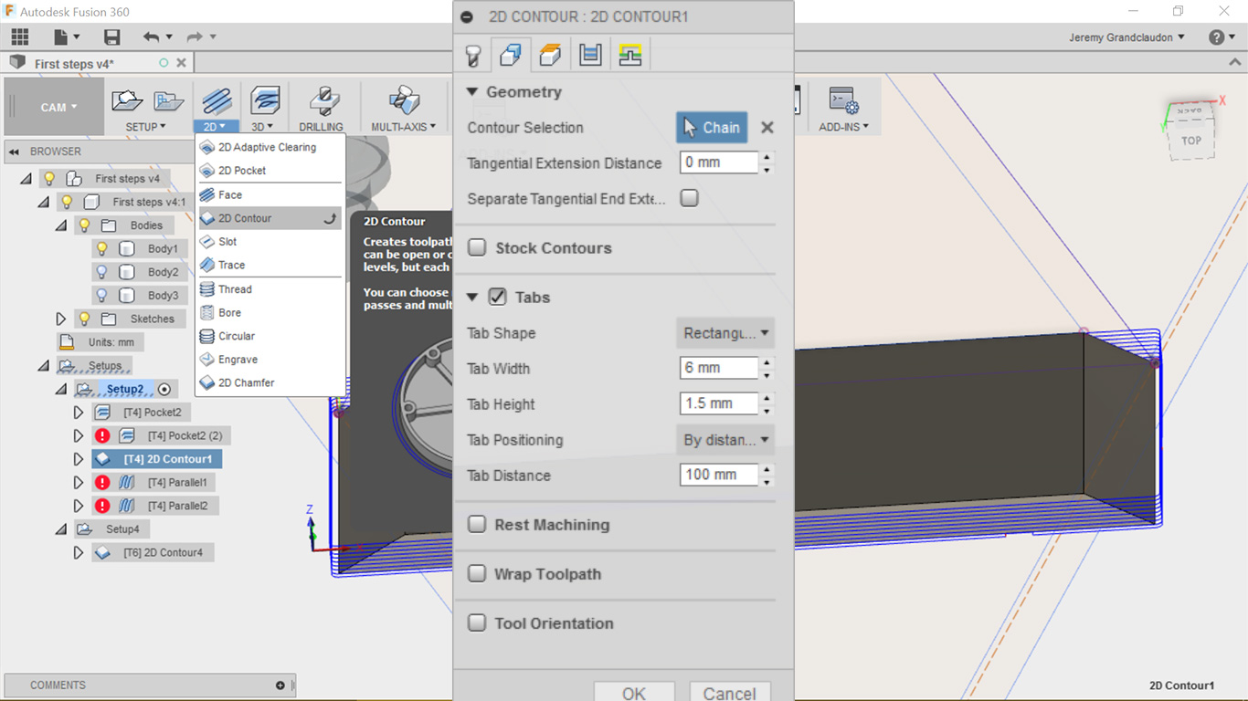
The two sides are done, now I need to do the contour to separate my piece for the main board. I will use the '2d contour' for this purpose
The tabs are quite except for the geometry and passes tab. The particuliarity for the geometry tab is the tabs section, it's allows you to place small pieces of wood, easy to remove, so to piece stay put during the milling
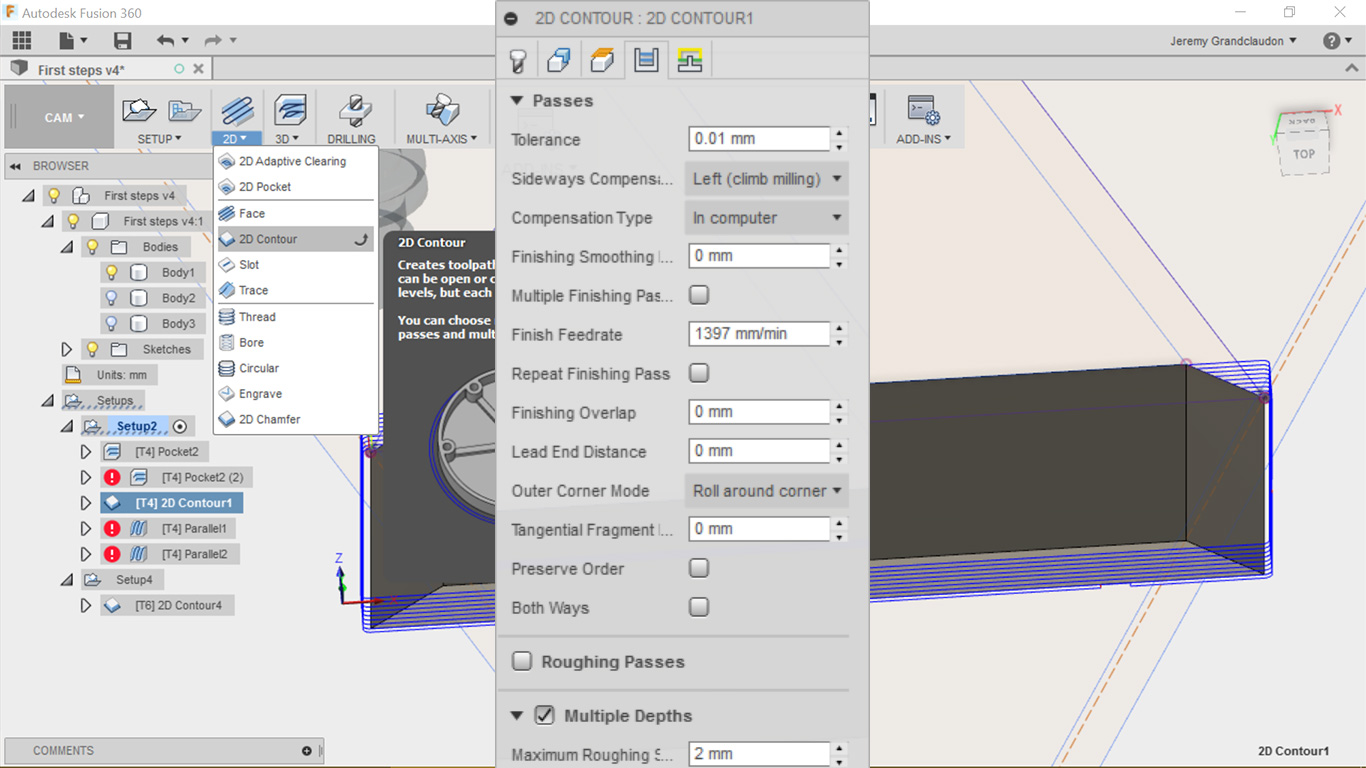
The passes tab give you a nice option 'multiple depths' where can tell it to go steps by steps (that you choose) until it reach the thickness of the board
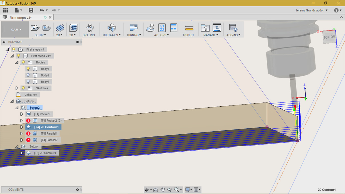
Here is the path for the contour with my tabs options and dephts
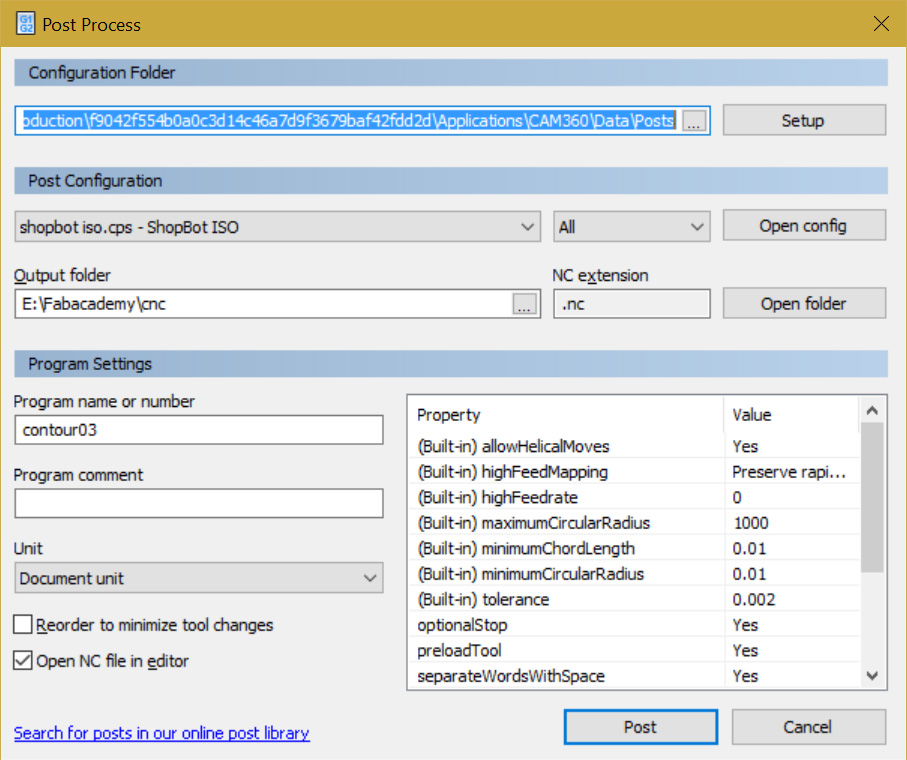
I have repeated the same steps for the bigger side of my design, I have just added a "2d slot" to ensure that the small and big triangle will slide cleanly. It's time to generate some Gcode!
A simple right click on the created jobs inside the setup allows you to select the Post process option where you can generate your Gcode and save it. I need to generate it for each side of the board and the contour
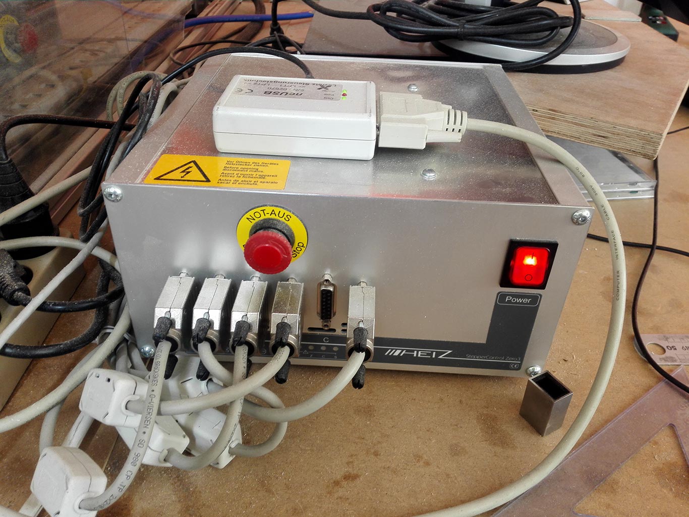
Enough with the virtual world, time to introduce you to our CNC! Here the controller
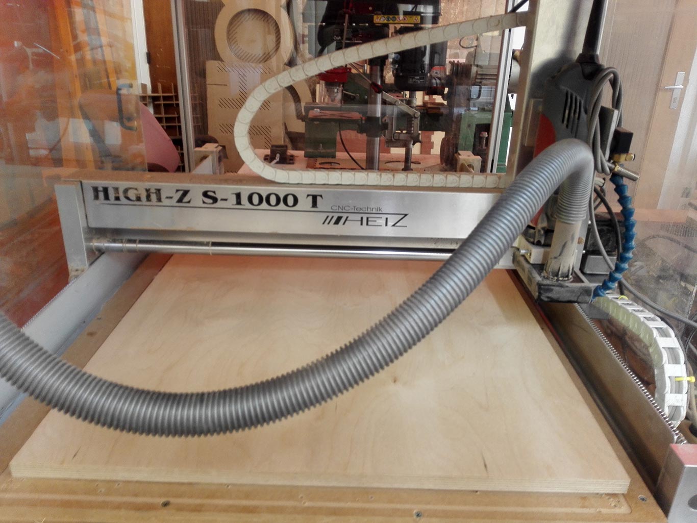
The CNC itself
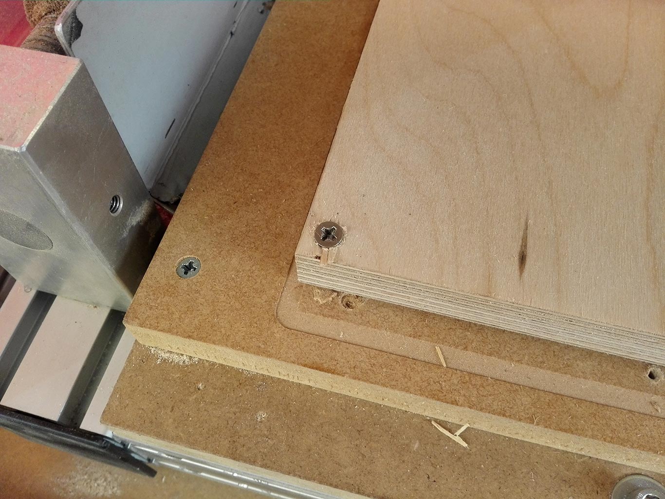
First step it's to ensure that your martyr board (the one under the board ready to be mill) is set and fixed. Then I will fix my board to it, 4 screws at each side.
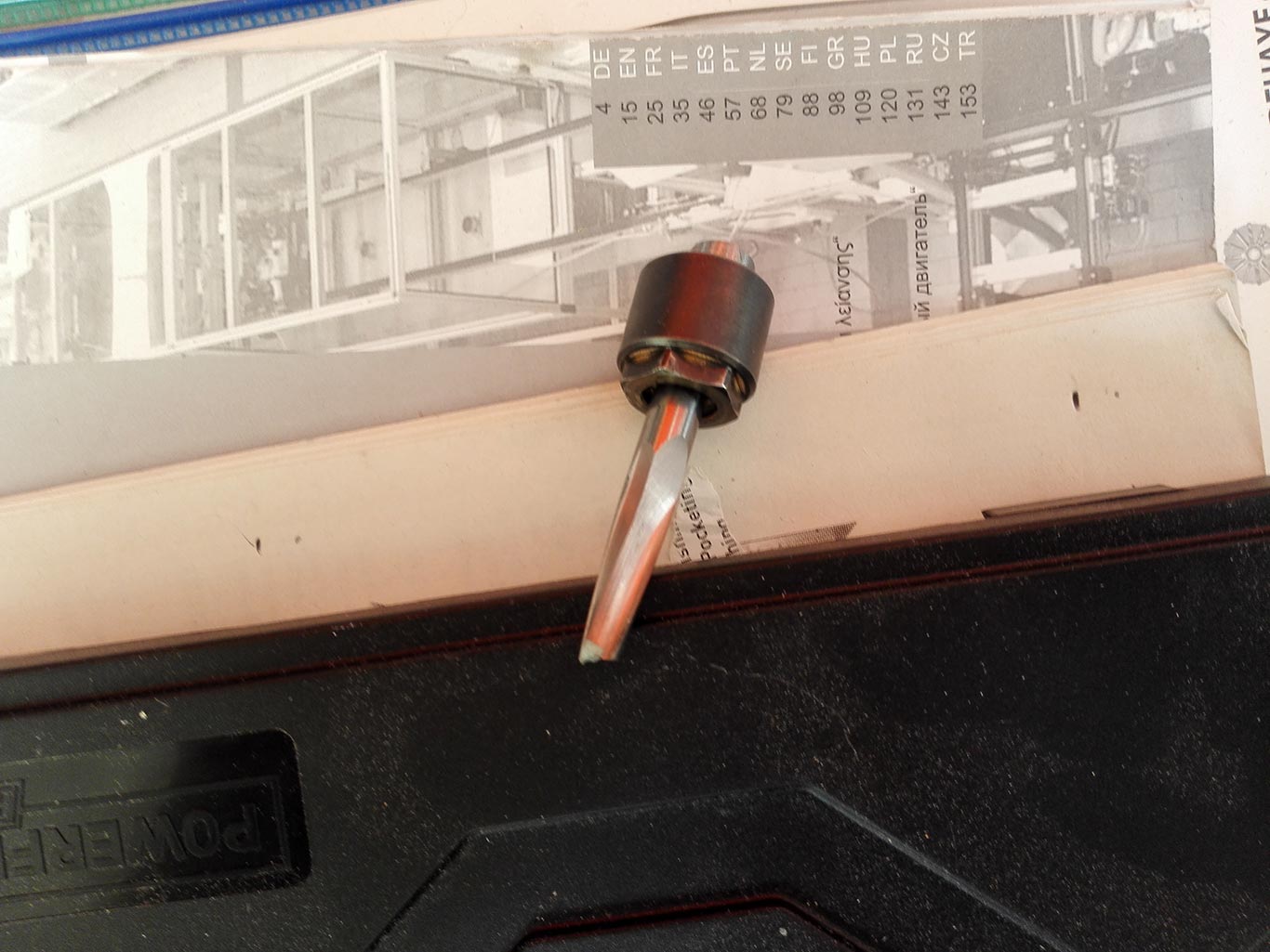
The hero of the day, the 8mm flat mill, it's my main tool for this assignment
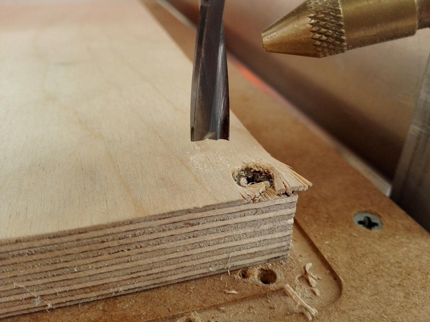
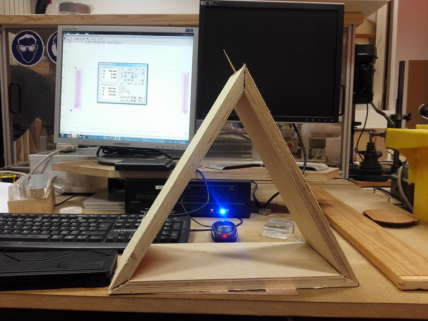
My board of birch is ready, I have now to set-up the XYZ position of my CNC in order to start. You can see the correct position here. When my tool is correctly set, if I move the tool by hand, it removes just a little of the board (when the Z position is saved, the CNC move the head up of 5mm in order to avoid incidents)
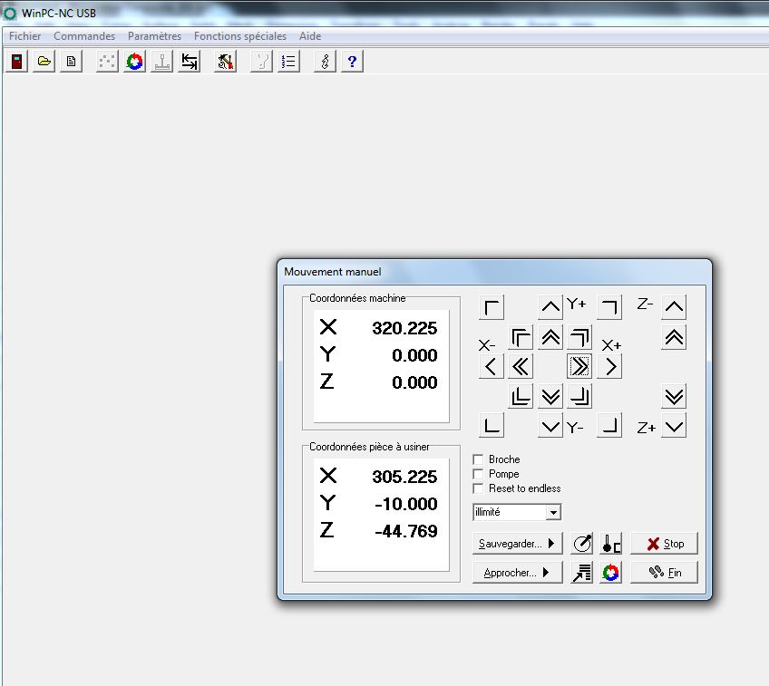
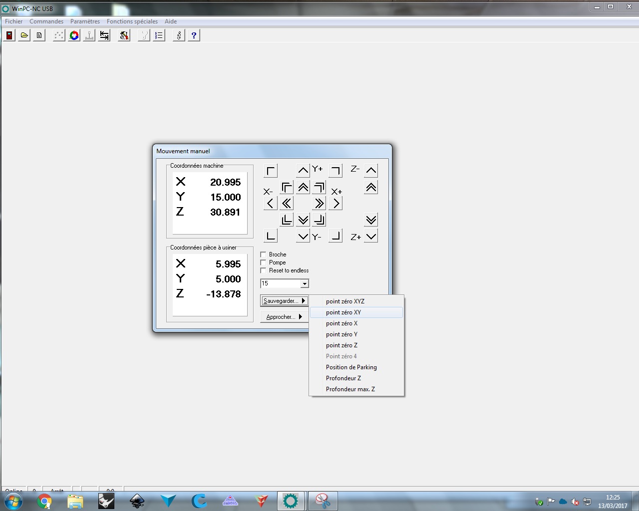
In order to achieve that position, I have used the software of my CNC and more precisely the manual positioning. The arrows in the middle move the CNC on the X and Y axis with different speed (slow, fast, by increment or freely) and the arrows of the right move the Z axis with the same principle
Once I'm on the desired position on X and Y axis, I save the position so I can come back when needed and It's fixed for the CNC
I do the same for the Z axis, I'm now sure that the CNC is correctly set on the right position and at the right height
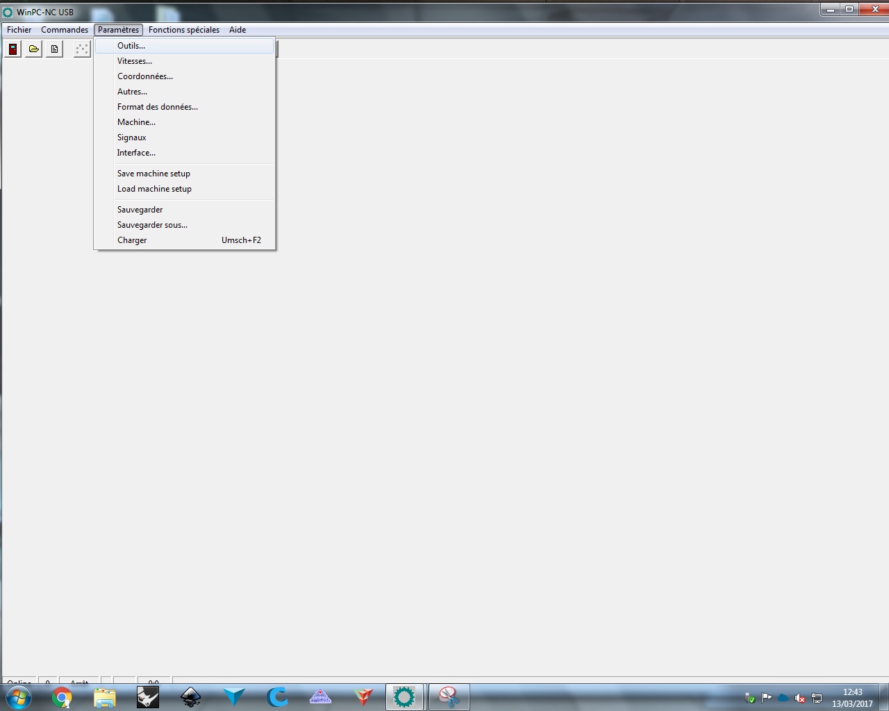
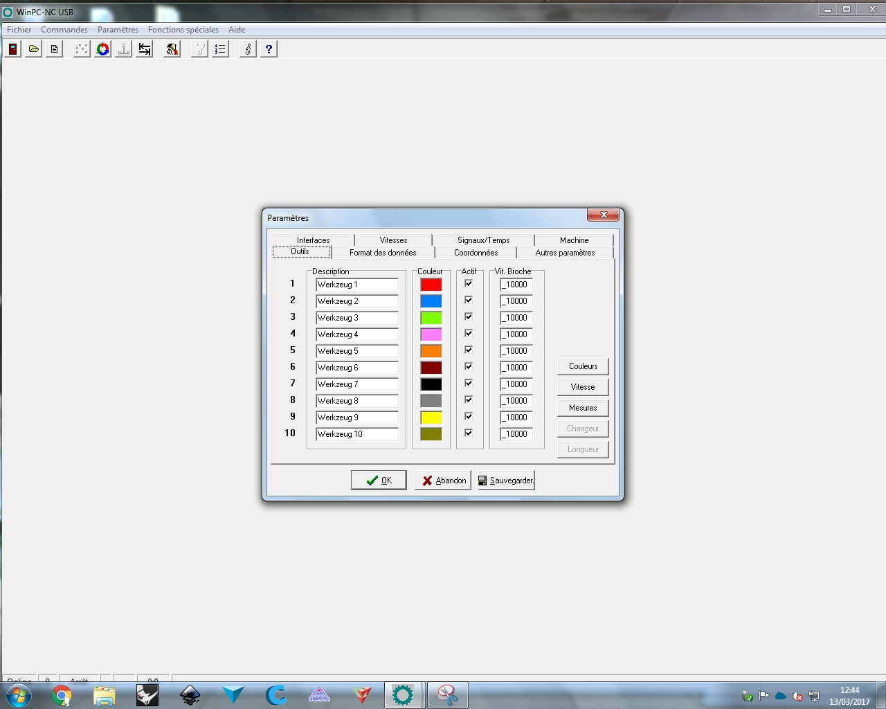
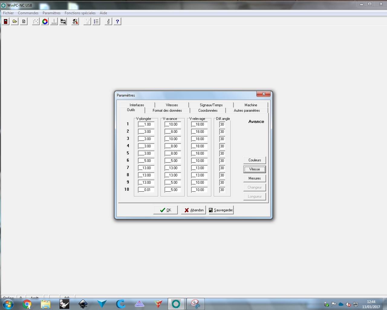
I will now set the speed for my tools
The settings are located in parameters --> tools --> Speed
My tool is the number 4 and I have made there my first big mistake. All the value are correct (the speed when the tool attacks the wood vertically and the speed when the tool is not in contact with the material) except the speed when the tool is moving in contact of the material. It's way too slow and I have burned a few centimeters of my board. I was just next to it so I stop and quickly check on the internet what was happening. In fact, the speed was to slow at 10mm and after a few tests, I have discovered that around 18-20mm, it's working very fine with a nice and clean cut
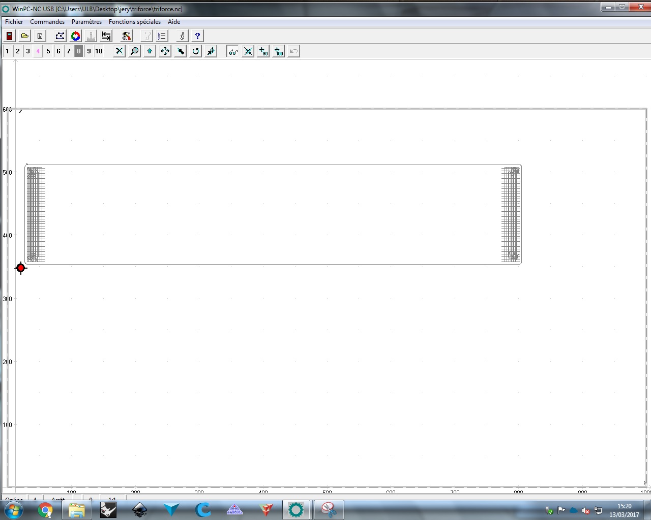
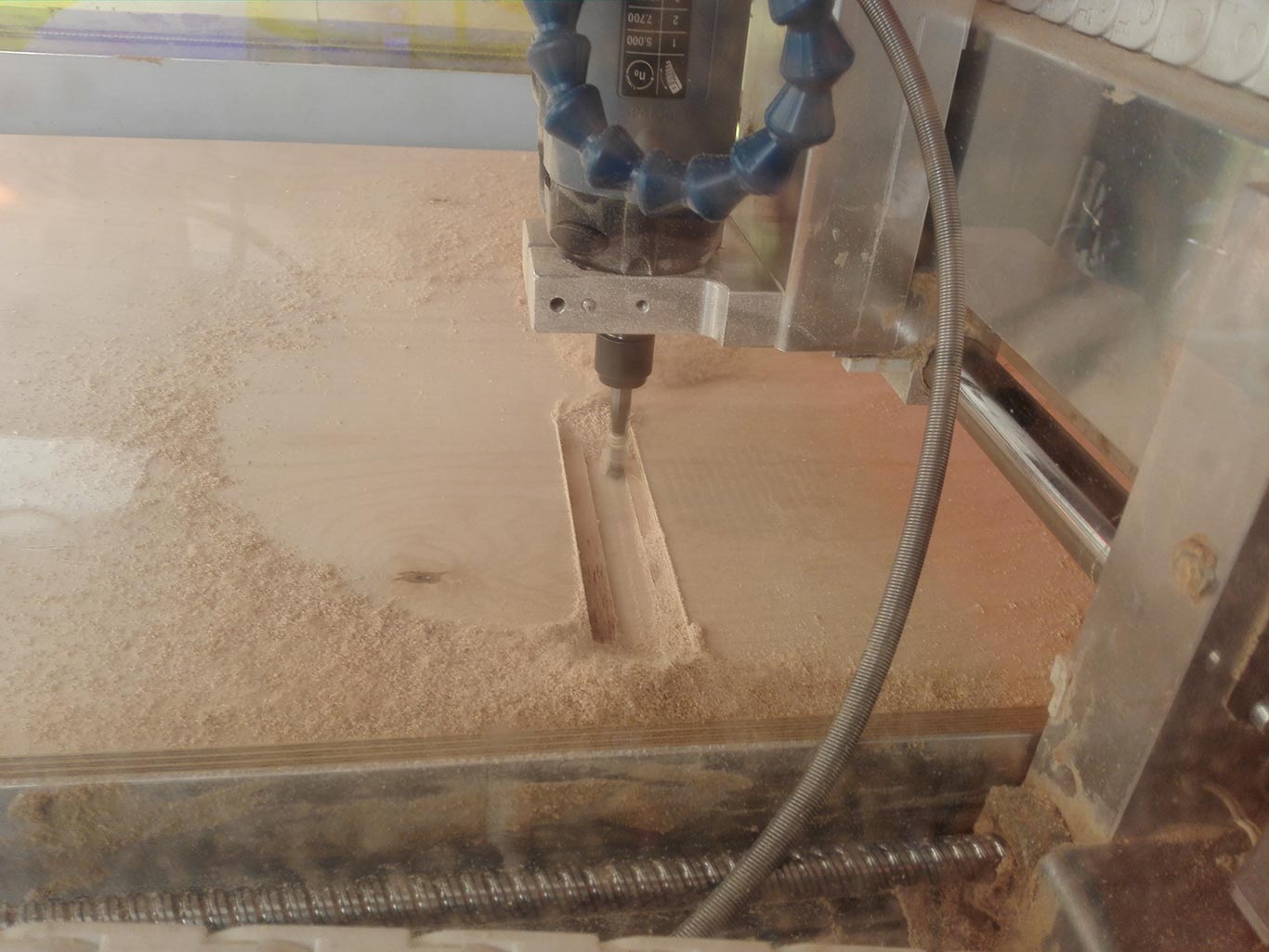
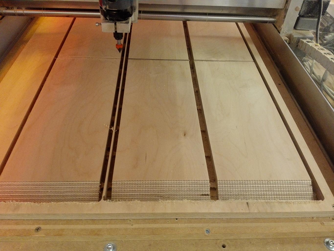
The CNC and tooling are set, I can now load my gcode generated with Fusion360 and launch the job, here the side of the small pieces.
The job is ongoing and this time nothing is burning so let's call that a success!
You can see here the tabs who keeps my pieces in place during the contour.
The interior triangle after milling, ready for sanding and assembly
It's time to move to the pieces of the exterior triangle
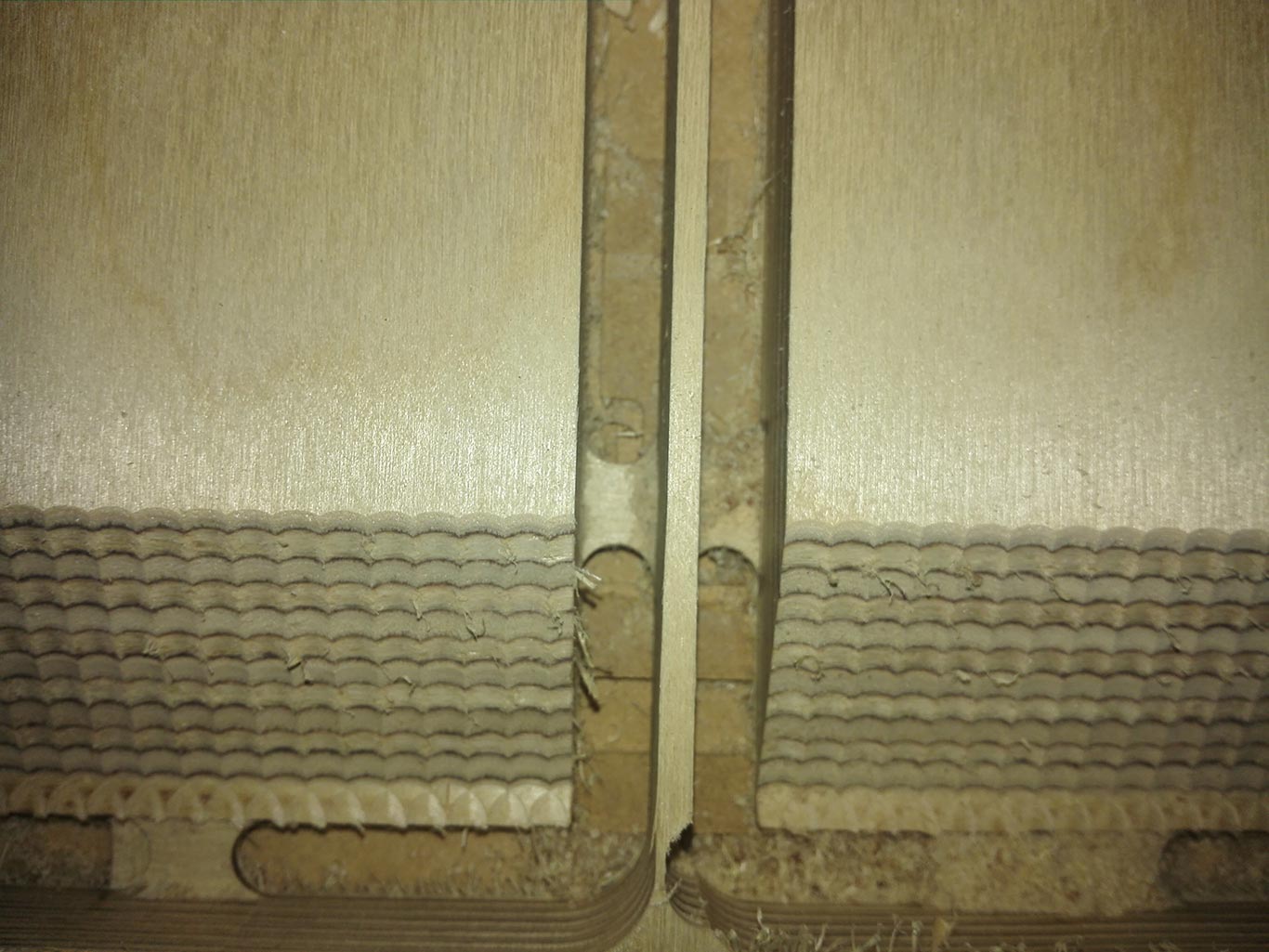
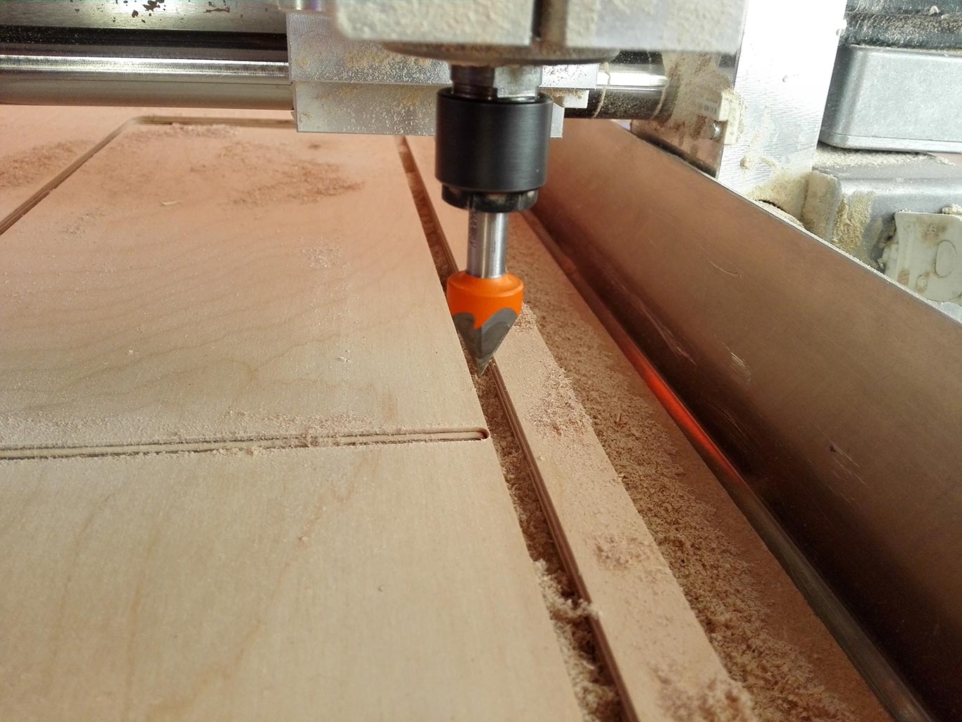
You can see here the V mill I have use to made the slot in the exterior triangle so each part of the small triangel can slide into it (theory, I will come back later on it)
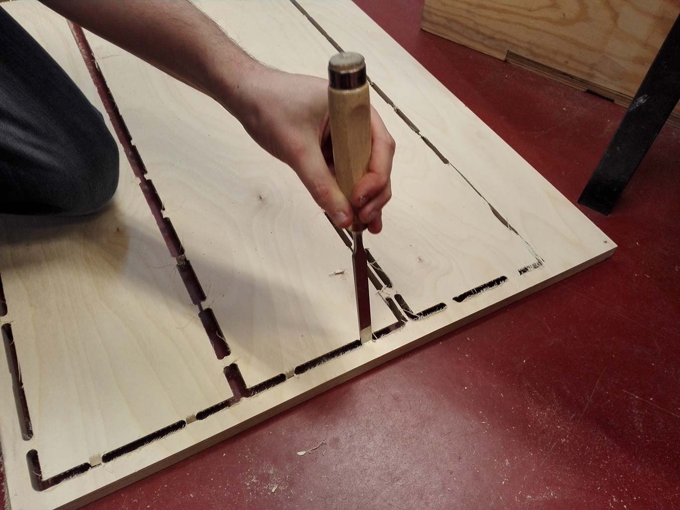
Removal of the tabs after completion of the milling
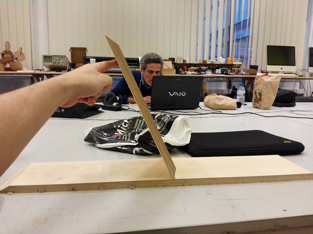
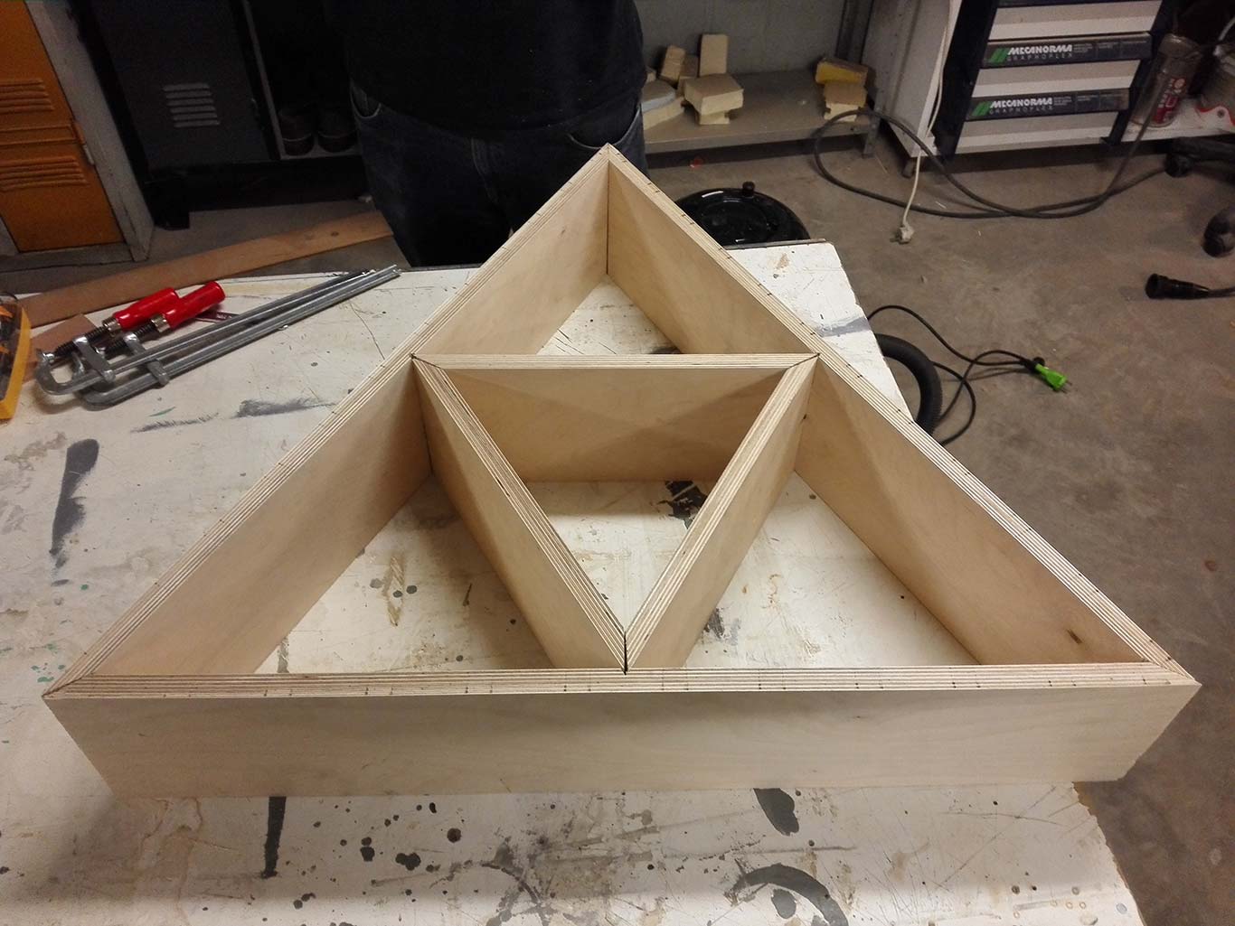
Small test, It can works!
And it's the disaster : I have sand to much on the interior triangle and now the angle made by the two pieces are more than 60°. It doesn't fit perfectly anymore and I haven't plan enough margin when I made the slot (design in Fusion and the reality of the material are not alway on the same page :( ))
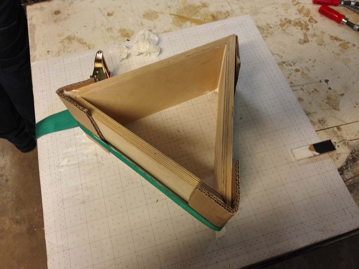
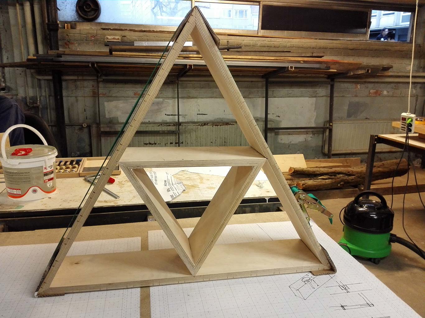
No time to do something else, I have tried to glue them together with the "belt technique" and some carboard to protect it
It doesn't look to bad, anyway a version 2.0 is already in the CNC to fix my mistake!
Summary : This assignment was really fun since the beginning of my days as FabManager, the CNC was my least favorite machine Now I have seen the potential in it and I really love it. THe main difficulty is the gap between the design our you CAD tool and the reality of the material. Finition are tricky too, I have made the experience first hand
It's also the most dangerous machine with the risk of fire or serious injury never really far away.
I can't wait to use it again and try different joint technique (the real difficult part in the design) to use a minimal amount of tool during the milling and the assembly