Embedded networking and communications
Assignment
- Design and build a wired and/or wireless network connecting at least two processors.
Learning outcomes
- Demonstrate workflows used in network design and construction.
- Implement and interpret networking protocols.
Have you
- Described your design and fabrication process using words/images/screenshots.
- Explained the programming process/es you used.
- Outlined problems and how you fixed them.
- Included original design files and code.


Design a fabduino
-
In previous projects, I had troubles implementing serial communication with the ATtiny44 microcontroller, so, for this week, I decided to use the ATmega328, wich is completely compatible with the Arduino comunicaction protocols.
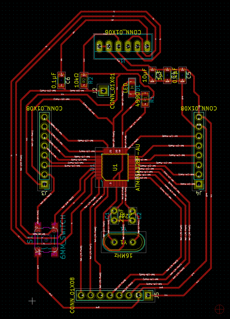
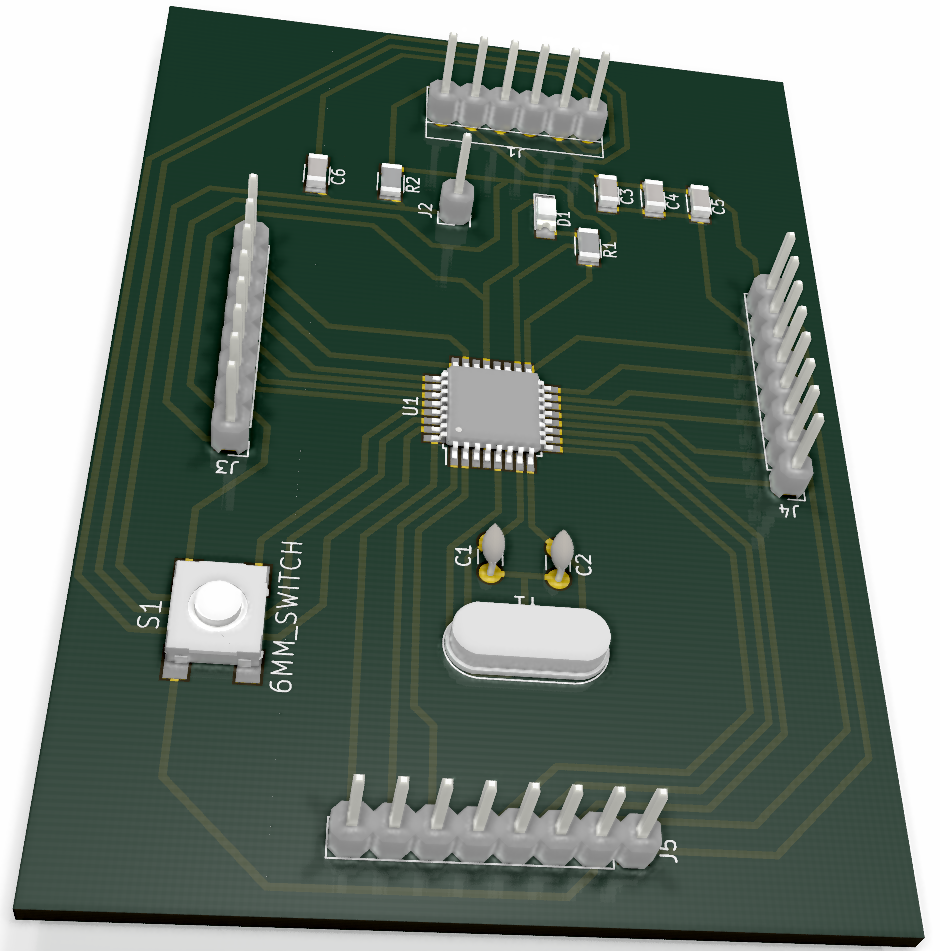
Since it is a large microcontroller, I wanted to have a board that could be reused in other projects, so I redesigned the fabduino. I had two reasons for this, first, I wanted to make my own design, and second, our milling machine doesn't do well when the traces are too close toghether.
My design uses more space on the pcb (9 cm by 6 cm), but works very well with the milling machine. Something I noticed until the board was milled was that the footprint of connector J1 had bigger pads than the other connectors, so I should have used that footprint for all of them. Also, my next design will include tracks for some pins that were left unconnected in this design, and a pin 13 LED for quick tests of the board.
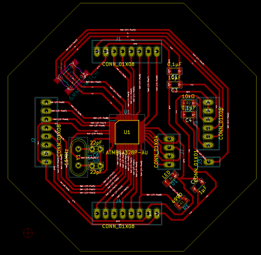
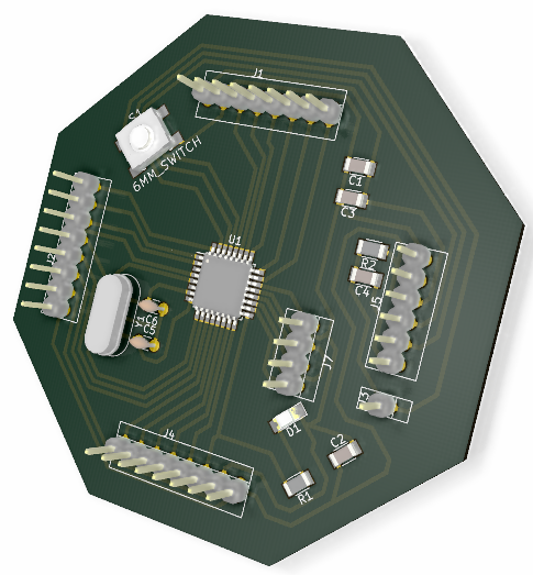
After that, I rearranged the distribution cf components, and designed another fabduino. The new design is a little smaller, and has an octogonal shape. It has the same distribution dor the pins, but I added pins for ADC7, ADC8 and AREF.
With two Arduino compatible boards, I decided to try the I2C protocol for communication. Also, one of the examples on the Arduino site was used as a starting point for my code (MasterWriter example)
I2C communication
-
First, the Arduino I2C communication needs the Wire.h library, so it must be imported to the code. I2C in Arduino works by simply connecting pins A4 and A5 on the firs board to the same pins on the second board.
The two boards have different code, one is the master, wich sends information, and the other is the slave, wich receives information. For this assingment I wanted to use a sensor, and send information from that sensor between boards.
The master board has an ultrasonic sensor, wich measures the distance of an object placed before the sensor (in a range between 1 cm and 50 cm), and sends the value of that distance to the slave board.
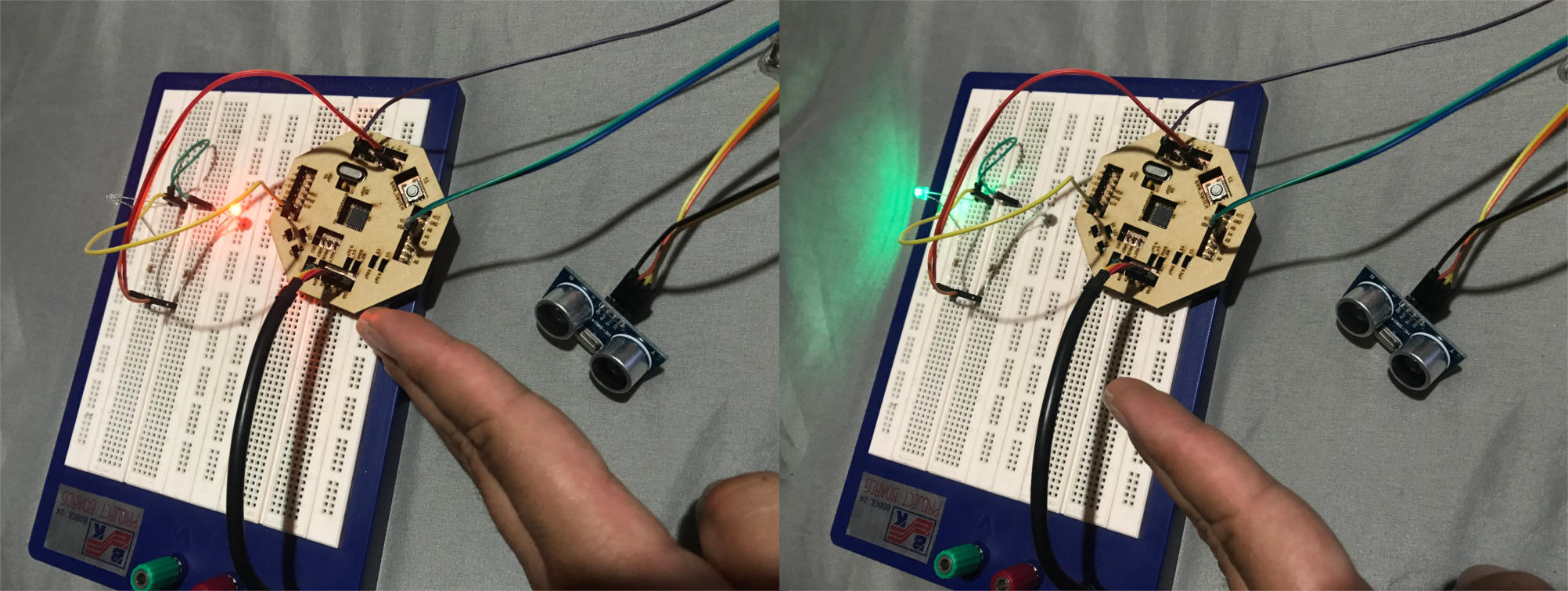
The slave board receives the distance information, and according to the value, lights an LED.
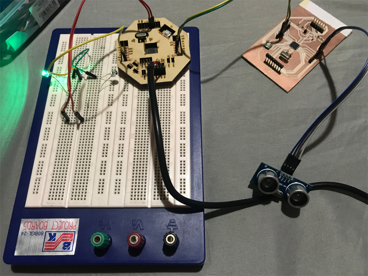
If the object is closer than 10 cm, a red LED lights up. If the object is further than 10 cm, a green LED lights up.
Master board code
-
The code on the master board in charge of the communication is:
#include "<"Wire.h">"
int trigPin = 12;
int echoPin = 11;
int led = 13;
void setup() {
Wire.begin(); // join i2c bus (address optional for master)
pinMode(trigPin, OUTPUT);
pinMode(echoPin, INPUT);
pinMode (led, OUTPUT);
}
byte x = 0;
void loop() {
Wire.beginTransmission(8); // transmit to device #8
//Wire.write("x is "); // sends five bytes
int duration, distance;
//byte x;
digitalWrite(trigPin, LOW); // Added this line
delayMicroseconds(2); // Added this line
digitalWrite(trigPin, HIGH);
// delayMicroseconds(1000); - Removed this line
delayMicroseconds(10); // Added this line
digitalWrite(trigPin, LOW);
duration = pulseIn(echoPin, HIGH);
distance = (duration/2) / 29.1;
x=distance;
Wire.write(x); // sends one byte
Wire.endTransmission(); // stop transmitting
//x++;
delay(500);
}
The code uses byte x as the variable to hold the value that will be transmitted. The line Wire.beginTransmission(8); starts the communication in address 8, this address must be the same on both boards. Then, the code takes the data from the ultrasonic sensor, and assigns the distance value to byte x, wich is transmitted with the command Wire.write(x);
Slave board code
-
The code on the slave board also includes the command Wire.begin(8); to star the communication (using the same address as the master), and then, the line Wire.onReceive(receiveEvent); registers an event whenever the master sends data to the salve. This event triggers a method to process the data of the communication:
#include "<"Wire.h">"
int led = 13;
int led4 = 4;
int led5 = 5;
void setup() {
Wire.begin(8); // join i2c bus with address #8
Wire.onReceive(receiveEvent); // register event
Serial.begin(9600); // start serial for output
pinMode(led, OUTPUT);
pinMode (led4, OUTPUT);
pinMode (led5, OUTPUT);
}
void loop() {
delay(100);
}
void receiveEvent(int howMany) {
while (1 < Wire.available()) { // loop through all but the last
char c = Wire.read(); // receive byte as a character
Serial.print(c); // print the character
}
int x = Wire.read(); // receive byte as an integer
Serial.println(x); // print the integer
if(x<10)
{
digitalWrite(led4, LOW);
digitalWrite(led5, HIGH);
}
else
{
digitalWrite(led5, LOW);
digitalWrite(led4, HIGH);
}
}
In the setup, the address 8 is assigned for the communication (the same address as the master). Then, the code assigns the read value to int x, and evaluates it. In case x is less than 10, the led on pin 5 lights up, otherwise, the led on pin 4 lights up.
Back