Output devices
Assignment
- Add an output device to a microcontroller board you've designed and program it to do something.
Learning outcomes
- Demonstrate workflows used in circuit board design and fabrication.
- Implement and interpret programming protocols.
Have you
- Described your design and fabrication process using words/images/screenshots.
- Explained the programming process/es you used and how the microcontroller datasheet helped you.
- Outlined problems and how you fixed them.
- Included original design files and code.


LCD board
-
We had some troubles with the milling machine this week. When the milling machine finally worked (for a while), I milled the board for the lcd example on this week's lesson.
-
I downloaded the files available at this week's lesson page, then preceeded to make the board.
The process for creating the board:
Download the board png file, and use photoshop to find the dimensios of the board.

Open the file on ArtCAM and set dimensions, then convert bitmap to vector and lower the contrast.
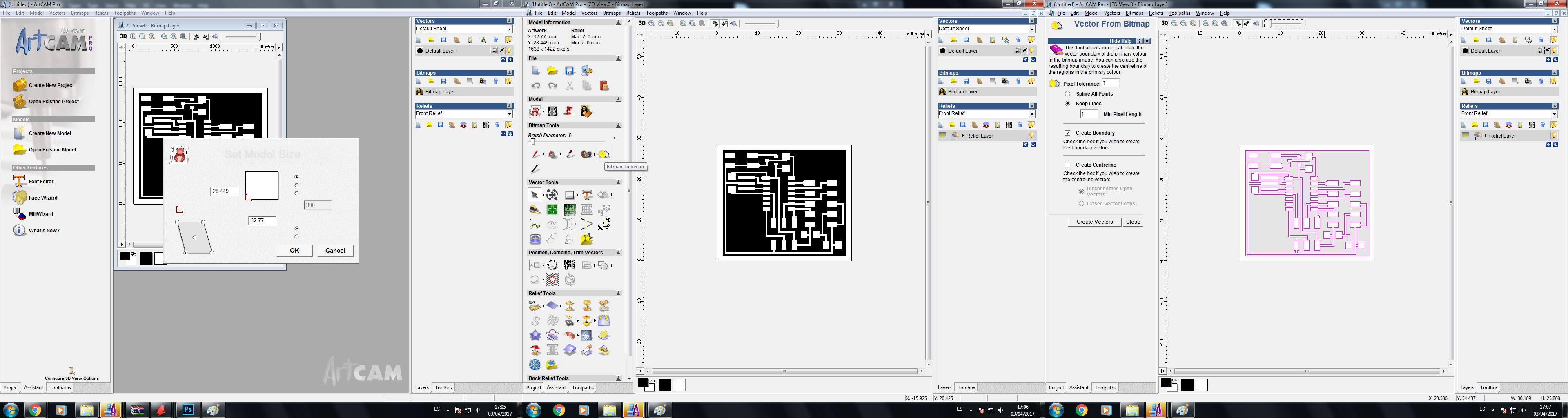
Then prepare the toolpath, set profile sido to outside, setup the tool (in this case D = 0,28 and step = 0,1) and finally setup material (thickness = 3mm, Z zero on top).

Then create the toolpath, check that the path is correctly set outside, and save it as a *.cn file.
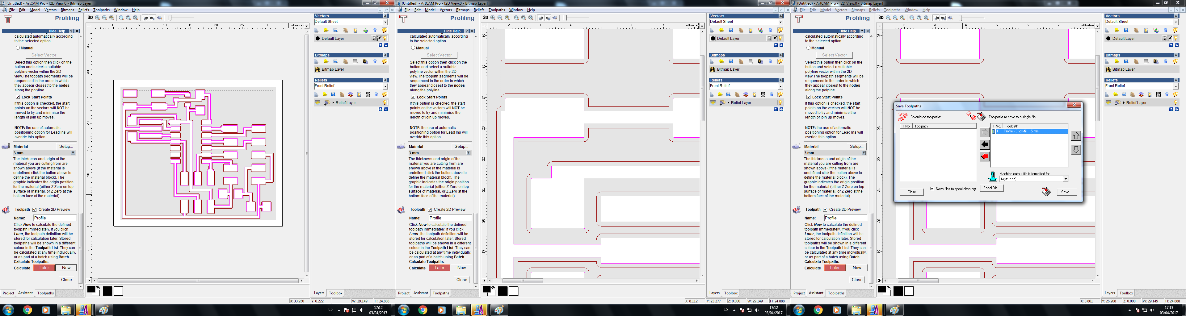
This file must be converted to a *.dat file, so we use OtuputDsp to open th *.cn file, setup settings (model X25, G0 speed 4000 mm/min, G1 speed 600 mm/min, Zdown 600 mm/min), then save to an usb flash memory.
Then, to the milling machine. We have a Kingcut y3.
Steps:
- The bed is fixed to the machine.
- The pcb is fixed to the bed.
- Turn on the machine and use hand control to go near the point to be set as zero. Then, spin the tool and move the head to z0, set all axes to zero and save the position. You can set other z0s.
- Then, use the folder button to browse the usb flash memory and find the file. Use enter to confirm file and start the process.

The machine is still not entirely set correctly, so my pcb traces have minor defects, but after a visual check, I determined it had no significant errors and was good to use.
So I proceeded to solder the components to the board.

And I loaded a blink program into it for testing.
After, I wired the lcd and loaded the lcd code form this week's lesson and it worked well.


My board
-
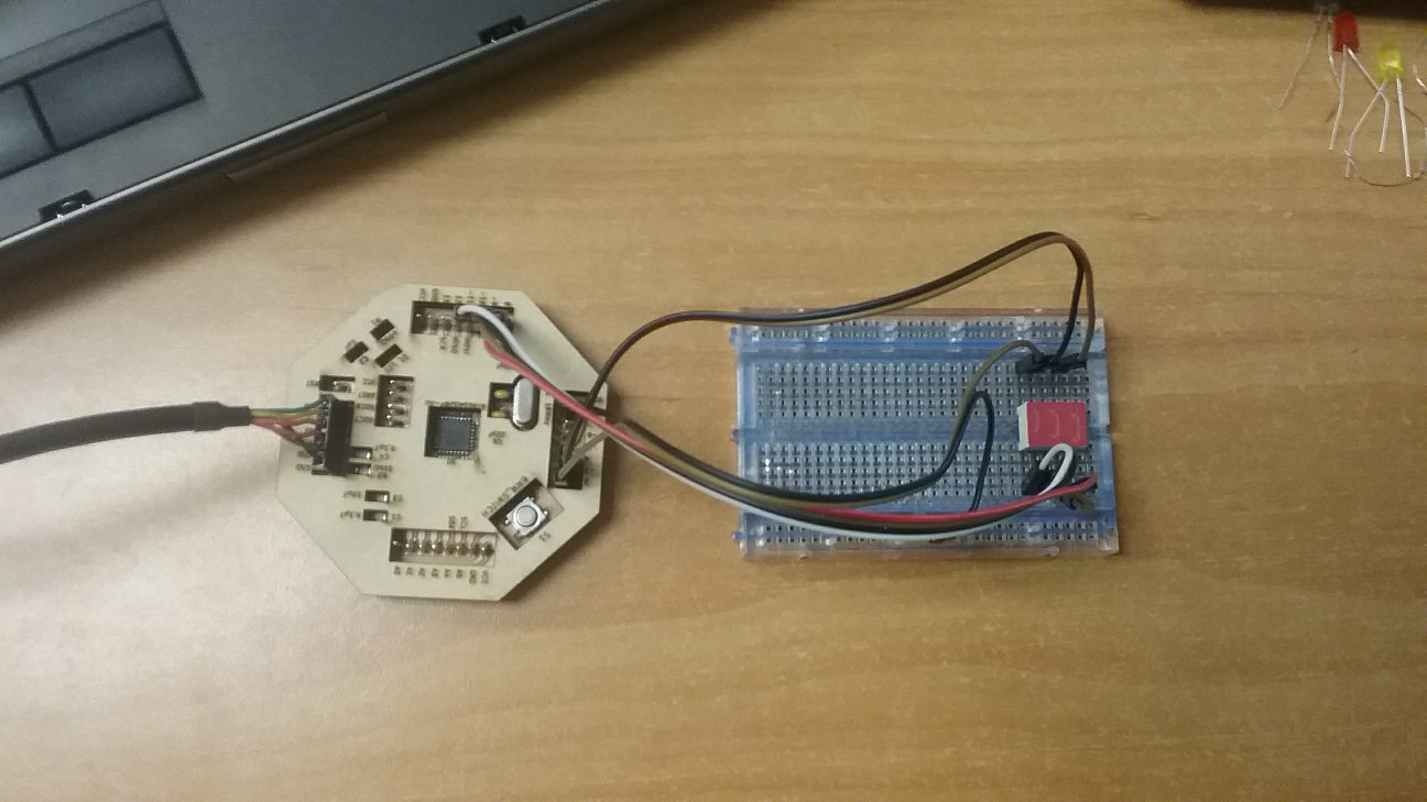
On week 15 I designed my fabduino, so I came back to this assignment to drive an output device with it.
The output device is a single digit lcd, and I want my board to display a m essage through this display. After reading the lcd datasheet I extracted the map for the lcd pins.
-
I then connected the lcd to my board.
-
This is my code:
//Created by Juan Carlos Miranda Castro for fabacademy 2017
int A = 2;
int B = 3;
int C = 4;
int D = 8;
int E = 9;
int F = 10;
int G = 11;
void setup() {
// put your setup code here, to run once:
pinMode(A, OUTPUT);
pinMode(B, OUTPUT);
pinMode(C, OUTPUT);
pinMode(D, OUTPUT);
pinMode(E, OUTPUT);
pinMode(F, OUTPUT);
pinMode(G, OUTPUT);
}
void loop() {
// put your main code here, to run repeatedly:
//H
digitalWrite(A,LOW);
digitalWrite(B,HIGH);
digitalWrite(C,HIGH);
digitalWrite(D,LOW);
digitalWrite(E,HIGH);
digitalWrite(F,HIGH);
digitalWrite(G,HIGH);
delay(250);
//off
digitalWrite(A,LOW);
digitalWrite(B,LOW);
digitalWrite(C,LOW);
digitalWrite(D,LOW);
digitalWrite(E,LOW);
digitalWrite(F,LOW);
digitalWrite(G,LOW);
delay(150);
//E
digitalWrite(A,HIGH);
digitalWrite(B,LOW);
digitalWrite(C,LOW);
digitalWrite(D,HIGH);
digitalWrite(E,HIGH);
digitalWrite(F,HIGH);
digitalWrite(G,HIGH);
delay(250);
//off
digitalWrite(A,LOW);
digitalWrite(B,LOW);
digitalWrite(C,LOW);
digitalWrite(D,LOW);
digitalWrite(E,LOW);
digitalWrite(F,LOW);
digitalWrite(G,LOW);
delay(150);
//L
digitalWrite(A,LOW);
digitalWrite(B,LOW);
digitalWrite(C,LOW);
digitalWrite(D,HIGH);
digitalWrite(E,HIGH);
digitalWrite(F,HIGH);
digitalWrite(G,LOW);
delay(250);
//off
digitalWrite(A,LOW);
digitalWrite(B,LOW);
digitalWrite(C,LOW);
digitalWrite(D,LOW);
digitalWrite(E,LOW);
digitalWrite(F,LOW);
digitalWrite(G,LOW);
delay(150);
//O
digitalWrite(A,HIGH);
digitalWrite(B,HIGH);
digitalWrite(C,HIGH);
digitalWrite(D,HIGH);
digitalWrite(E,HIGH);
digitalWrite(F,HIGH);
digitalWrite(G,LOW);
delay(250);
//off
digitalWrite(A,LOW);
digitalWrite(B,LOW);
digitalWrite(C,LOW);
digitalWrite(D,LOW);
digitalWrite(E,LOW);
digitalWrite(F,LOW);
digitalWrite(G,LOW);
delay(350);
}
Another practice
-
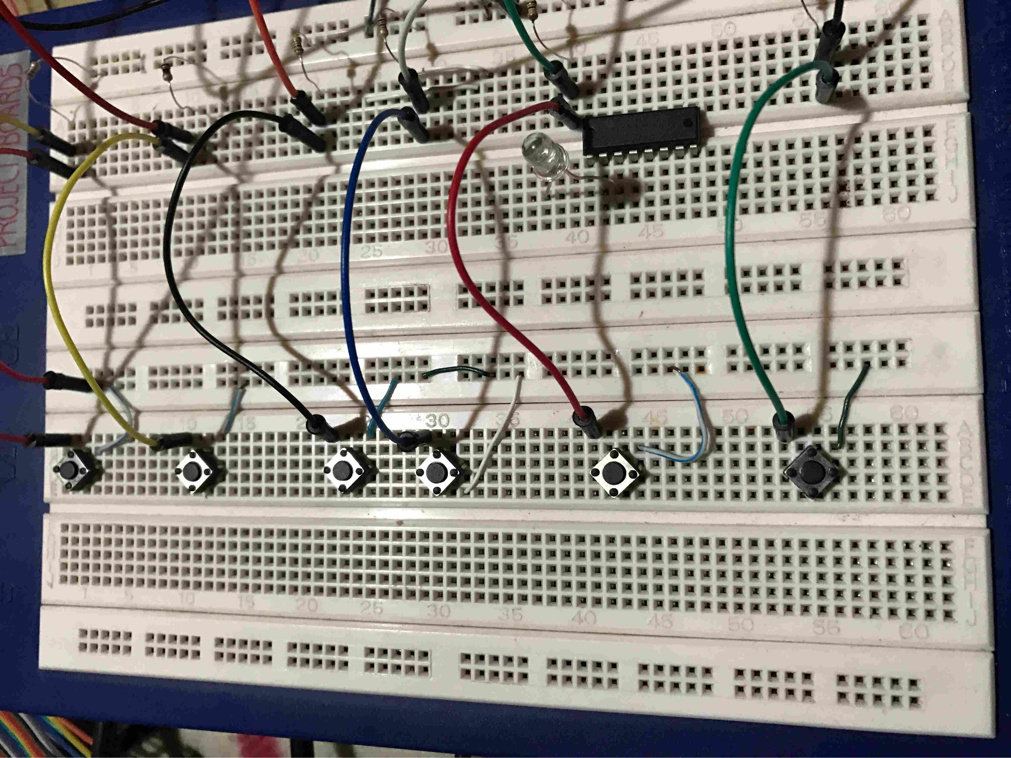
Since my project is a Braille keyboard, I wanted to start experimenting with buttons as inputs and one output to visualize the reading of buttons in the microcontroller. The outputs in this excercise will be an lcd, although the output for the actual project is digital text in a file.
Because of the problems with the milling machine, and the fact that I needed a lot of input pins, I worked with an Arduino for this test. My goal was to show on an lcd an output taken from a row of buttons. In this case, I only show which button or buttons are pressed. In future versions, these inputs must be converted to characters.
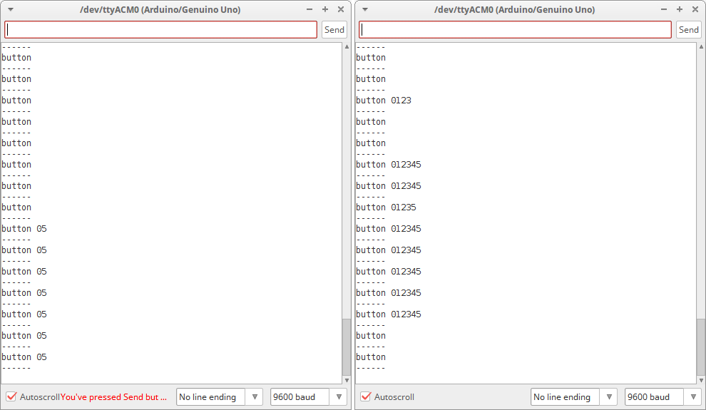
I first tested the circuit and the code with serial monitor.
Then added the lcd, wich uses IC2 connection.
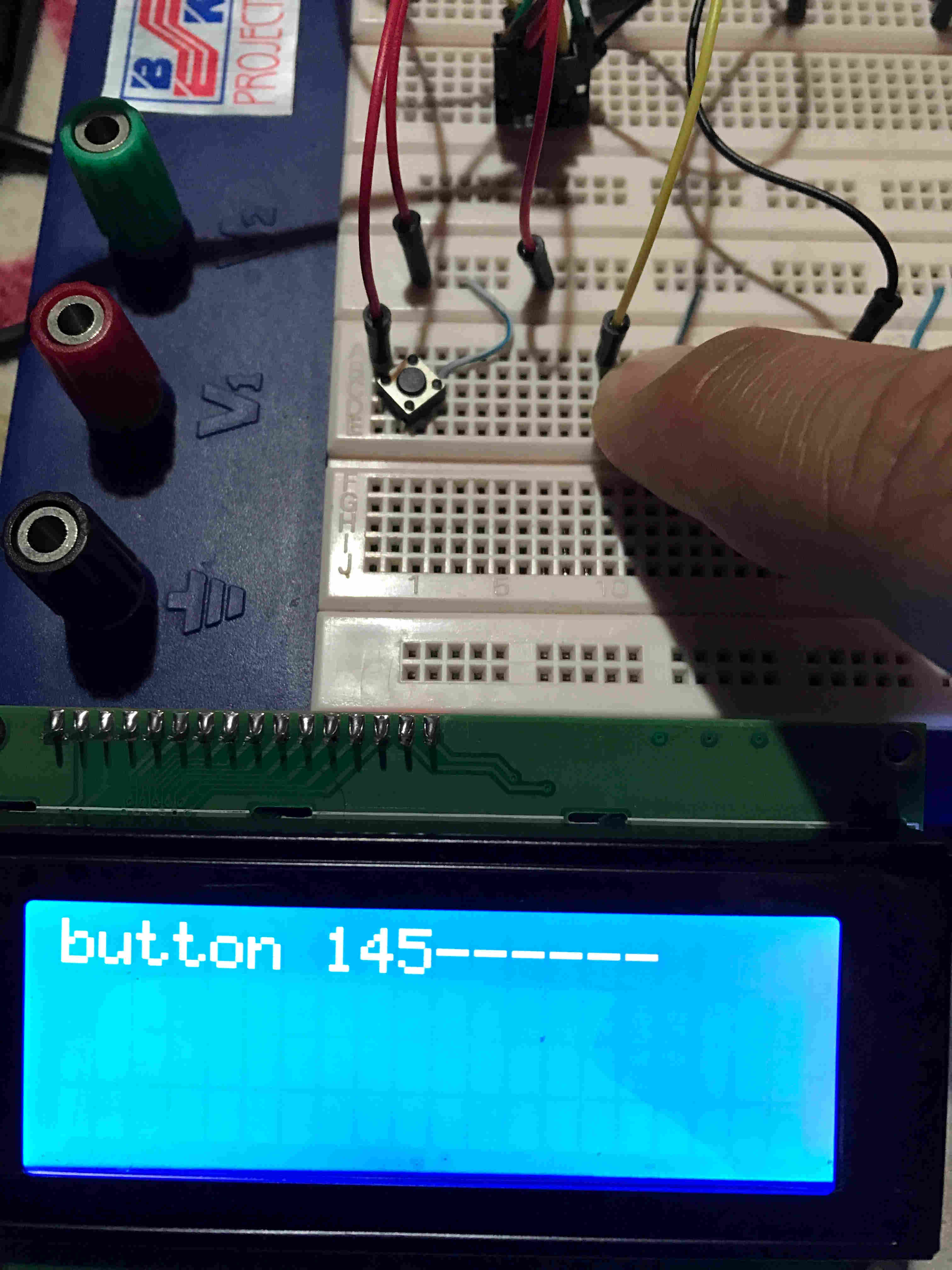
This is the code that reads the buttons and sends the string to the lcd.
/*
Button
Turns on and off a light emitting diode(LED) connected to digital
pin 13, when pressing a pushbutton attached to pin 2.
created 2005
by DojoDave
modified 30 Aug 2011
by Tom Igoe
modified By Juan Carlos Miranda Castro for fabcademy 2017
This example code is in the public domain.
http://www.arduino.cc/en/Tutorial/Button
*/
#include
LiquidCrystal_I2C lcd(0x27, 2, 1, 0, 4, 5, 6, 7, 3, POSITIVE);
//int buttonArray[6]; //this array will hold integers
int buttonArray[] = {2,3,4,5,6,7,8,9,11}; // this array will hold buttons
// constants won't change. They're used here to
// set pin numbers:
const int ledPin = 13; // the number of the LED pin
void setup() {
lcd.begin(20, 4);
lcd.backlight();
lcd.setCursor(0, 0);
lcd.print("hola");
delay(1111);
lcd.clear();
Serial.begin(9600);
// initialize the LED pin as an output:
pinMode(ledPin, OUTPUT);
lcd.setCursor(0,0);
lcd.print("hola");
for (int thisPin = 0; thisPin < 9; thisPin++)
{ pinMode(buttonArray[thisPin], INPUT); }
}
void loop() {
// read the state of the pushbuttons value:
// buttonState = digitalRead(buttonPin);
String mensaje = "button ";
for (int thisPin = 0; thisPin < 10; thisPin++)
{ int reading = digitalRead(buttonArray[thisPin]);
if (reading == LOW)
{
mensaje = mensaje + thisPin;
//mensaje = mensaje + reading;
}
}
Serial.println(mensaje);
lcd.setCursor(0, 0);
lcd.print(mensaje);
lcd.print("------");
// check if the pushbutton is pressed.
// if it is, the buttonState is HIGH:
Serial.println("------");
delay(50);
}
One more
-
Based on Neil's rgb led example, I designed my own board for an rgb led.
I used an attiny45 microcontroller for the board. The basic circuit has a 1 uF capacitor between vcc and gnd and a 10 k ohm resistor between vcc and rst. I have a common anode rgb led, which means it has a pin for vcc, and the other three are activated by connecting them to gnd or 0 V.
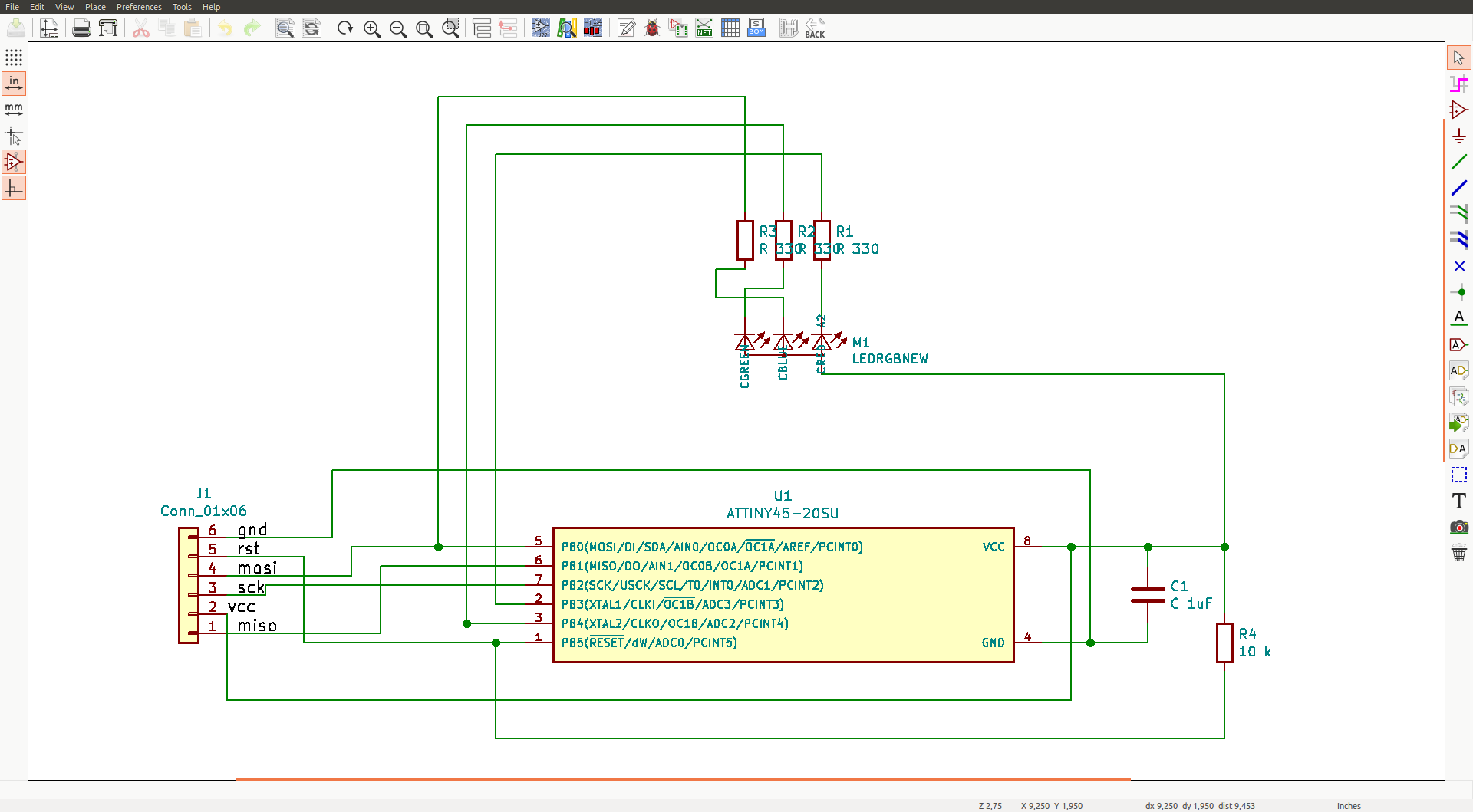
Then, I added one 499 ohm resistor for each color of the led. I used PB0, PB4 and PB5 as pins for the rgb, but I did not notice at this point that I was using the reset pin as I/O, wich is an error because it won't work as a programmable pin.
I then created the pcb layout for the board:
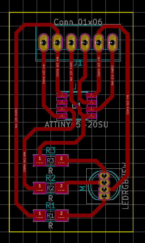

And the I fabricated the pcb and soldered it. I realizaed about my mistake because the led was not giving the red color, so I solved it by soldering a 330 ohm resistor between PB3 and the red pin of the led (I disconnected reset from this line).

The rgb board working:
This is the code that creates the color changing pattern:
/*
RGB
Turns on and off a light emitting diode(LED) connected to digital
pin 13, when pressing a pushbutton attached to pin 2.
created 2005
by DojoDave
modified 30 Aug 2011
by Tom Igoe
modified By Juan Carlos Miranda Castro for fabcademy 2017
This example code is in the public domain.
http://www.arduino.cc/en/Tutorial/Blink
*/
int red = 3;
int green = 0;
int blue = 4;
void setup()
{
pinMode(red, OUTPUT);
pinMode(green, OUTPUT);
pinMode(blue, OUTPUT);
}
void loop()
{
setColor(255, 0, 0); // red
delay(1000);
setColor(0, 255, 0); // green
delay(1000);
setColor(0, 0, 255); // blue
delay(1000);
setColor(255, 255, 0); // yellow
delay(1000);
setColor(80, 0, 80); // purple
delay(1000);
setColor(0, 255, 255); // aqua
delay(1000);
}
void setColor(int red, int green, int blue)
{
red = 255 - red;
green = 255 - green;
blue = 255 - blue;
analogWrite(redPin, red);
analogWrite(greenPin, green);
analogWrite(bluePin, blue);
}
Back