Computer-Controlled Machining

ShopBot

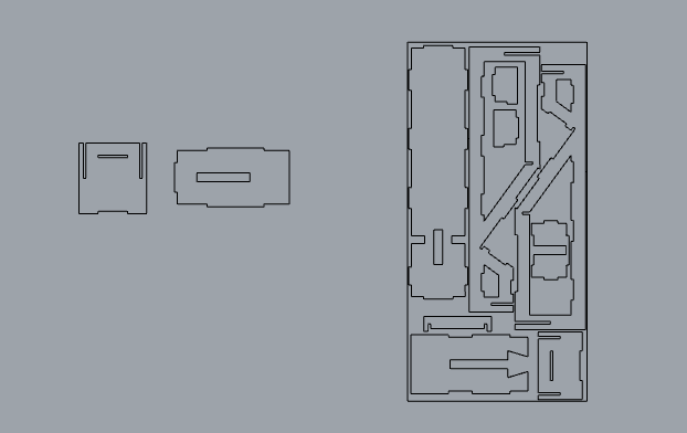
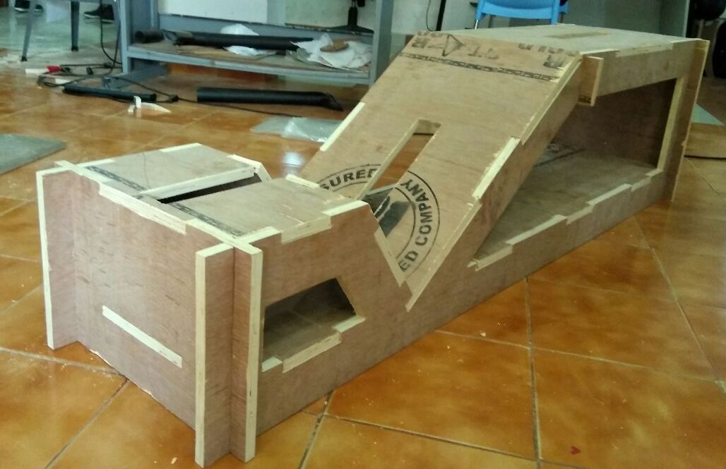
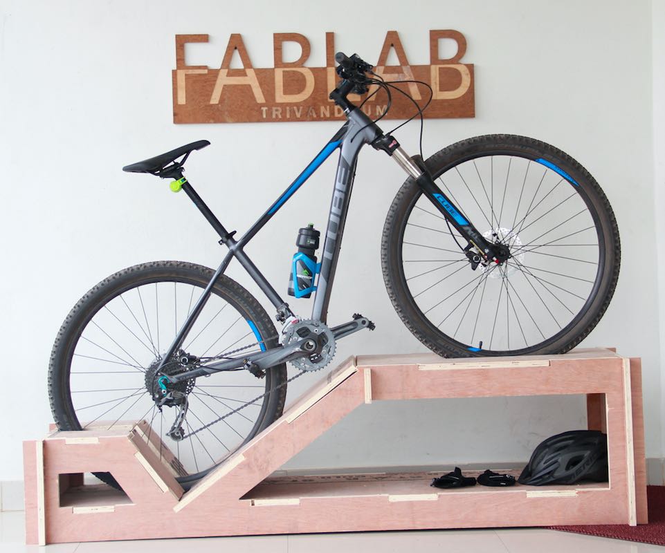
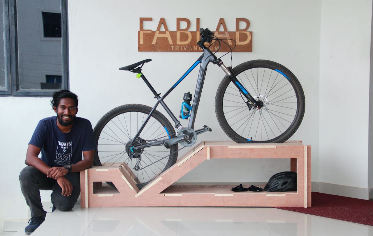
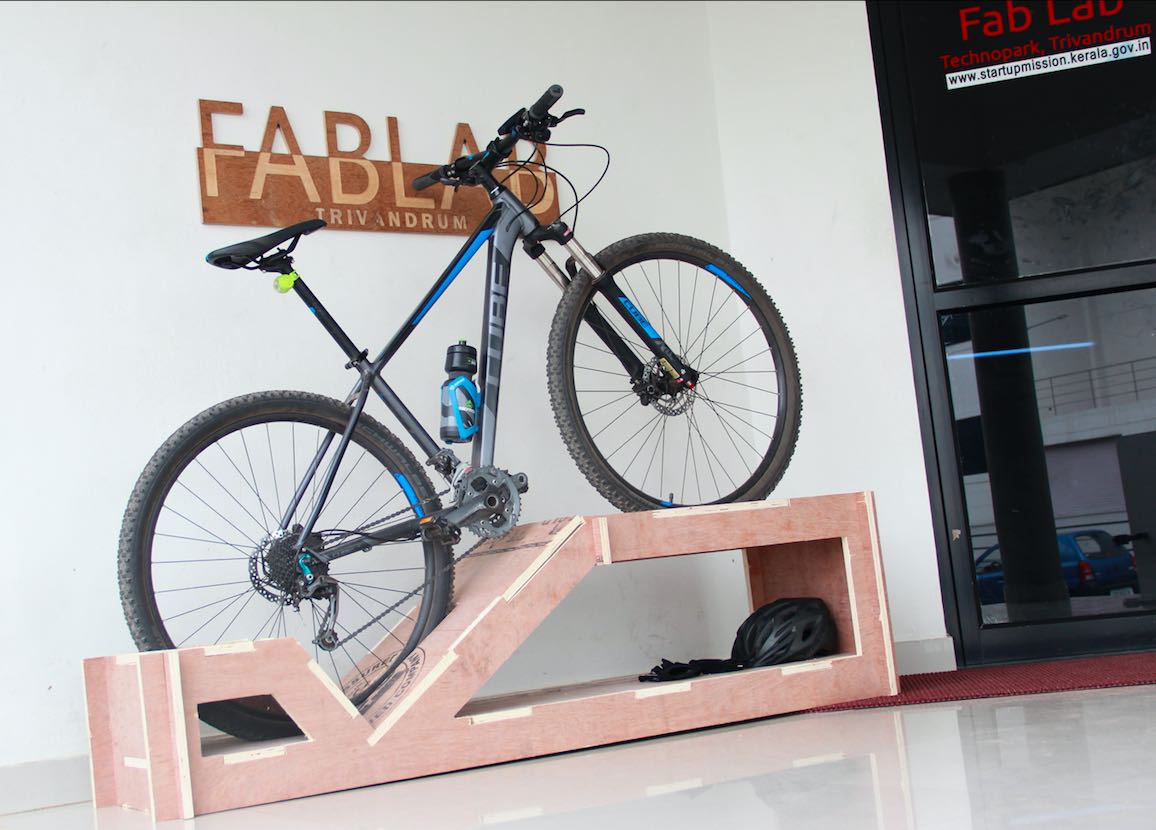
The assignment for this week is to build something big using CNC machine.

Machine Description


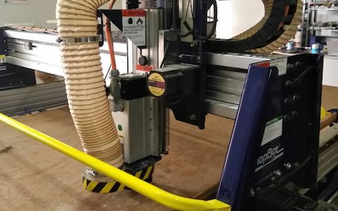
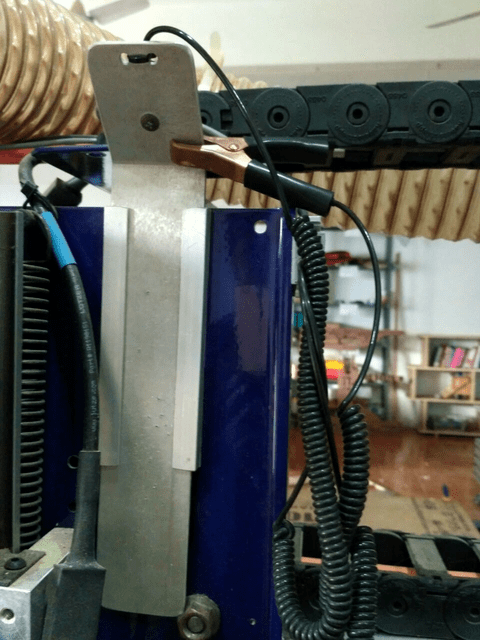
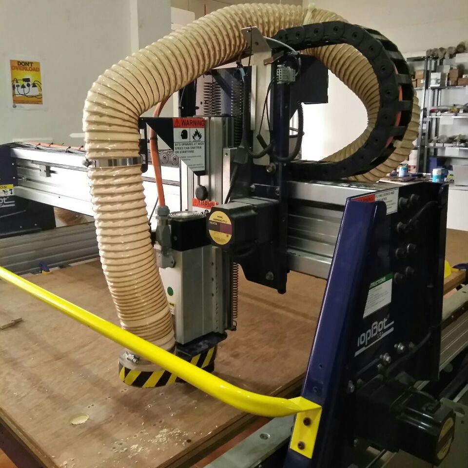
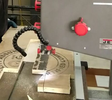
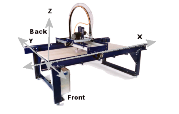
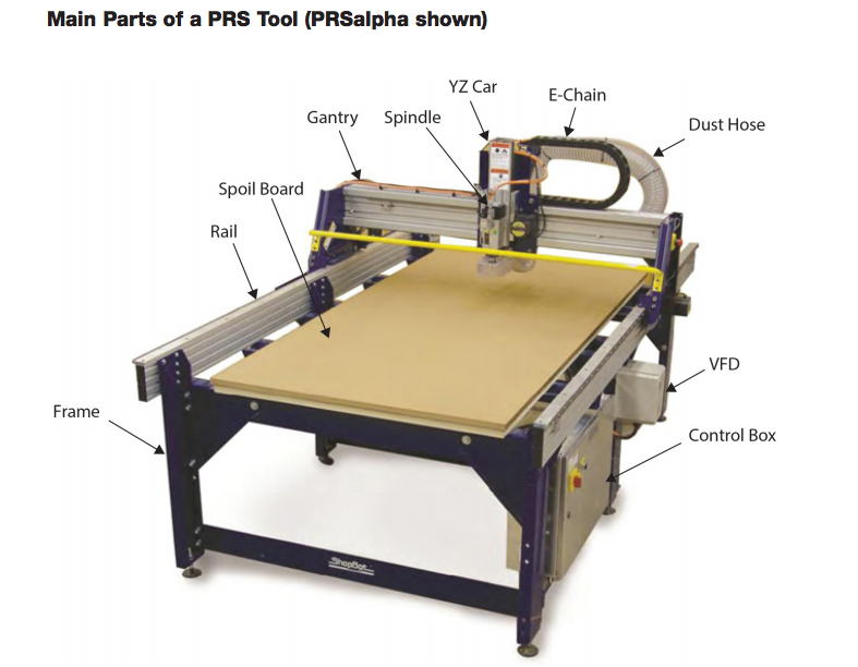
We have the ShopBot at our FabLab for this purpose. Its a large milling machine with a bed size of 8 x 4 feet which can mill wood, and plywoods. It base is fixed and the head has railings to move in x, y and z axes.


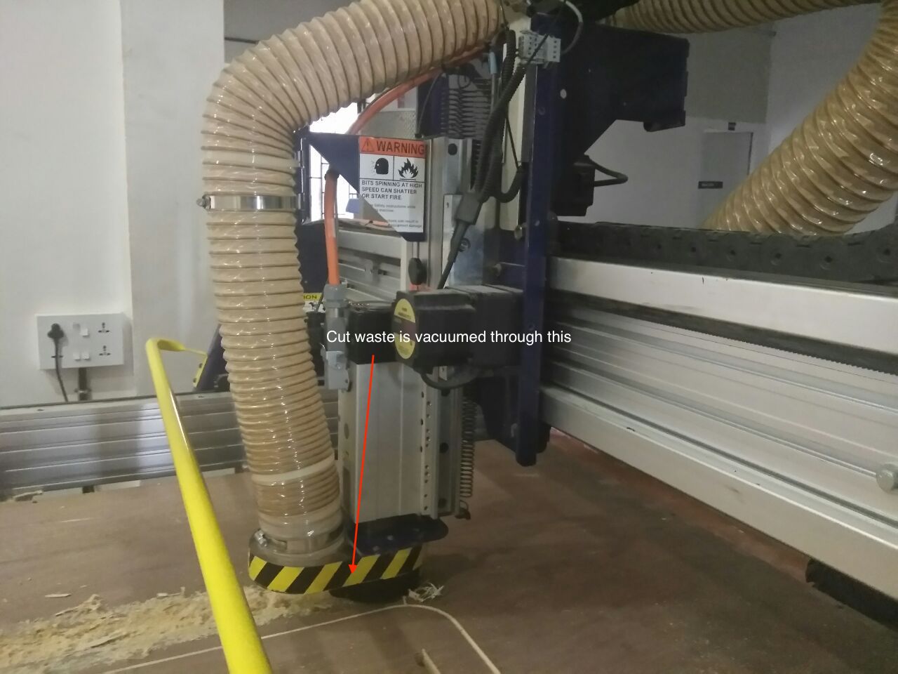
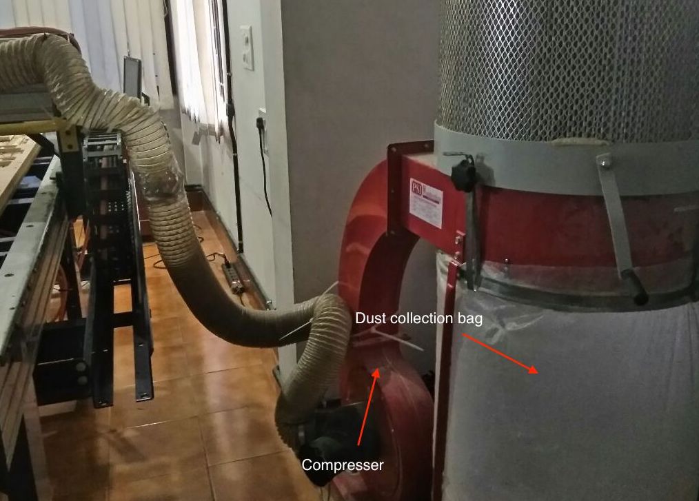
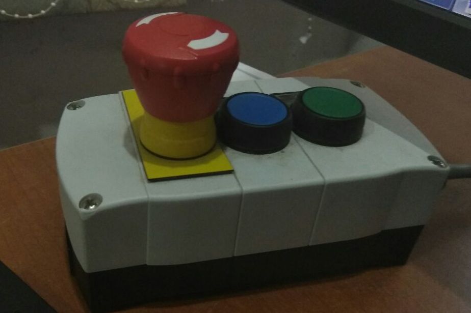
The CNC machine has a compresser attached to it, so that the cut particles do not fly around and mess up the lab. Its important to wear safety protection whenever using this machine, esp. eye gear and gloves.

Tooling Details

The following details are obtained from the documentation provided by Vishnu Easwaran

drill bit vs end mill :- Drill bit can be differentiated by its pointed tip which is for drilling into the object whereas end mills have flat tips and they are for milling away chunks from the object.
End mills give a flat cut while drill bit gives a curved cut.
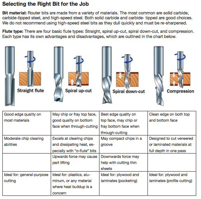
flutes :- they are the spiraing sharp part along the surface of an end mill. They are for cutting through the object and for clearing the chips. Less number of flutes means chips will be cleared easily but the cut will be of rough finish. Higher the number of flutes we will get a smooth finish but the chips cut off wont be cleared effectively.
coating :- the end mills undergoes a lot of stress and strain while milling. So to provide extra strength, it is very common, to coat the bit in some ceramic bke nitrites which increase their endurance.
center cutting :- when you hold the bit upside down an look, if the flutes meet at the center then it is center cut and is good for cutting downwards but not for clearing the debris. If the flutes terminate before reaching the center it is non-center cutting and it is good for clearing the debris but not good for cutting downwards.
up/down cut :- if you hold the end mill by its head (the portion without flutes) and rotate it clockwise if you get the impression that the flutes are spiraling up then it is up cut and if it feels bke it’s spiraling down then it is down cut. Up cut is good for clearing the debris easily but results in a rough top surface while down cut is bad at clearing debris but gives a smooth top surface. Then there is something called center cut, where from bottom till middle it is down cut and from there till top it is up cut. This gives smooth top and bottom surfaces but very bad at clearing the cut out chunks.
flat/ball end :- flat end leaves flat surface and steps are formed when used for making cavities. Ball end leaves curved surfaces and forms curved finish while cutting cavities.

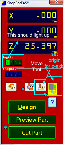
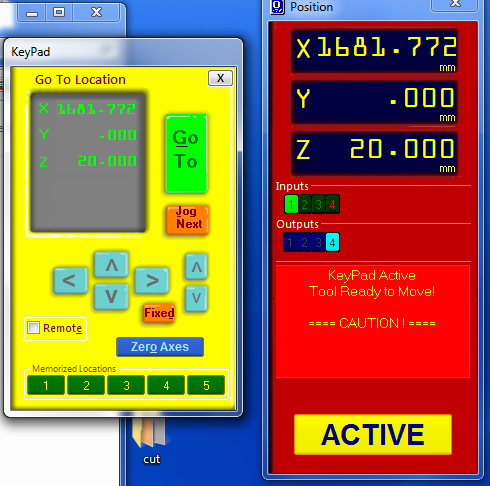
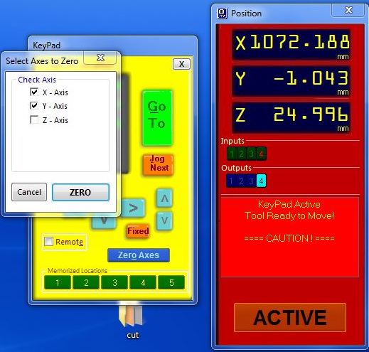
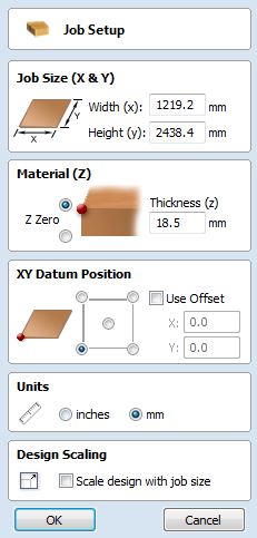
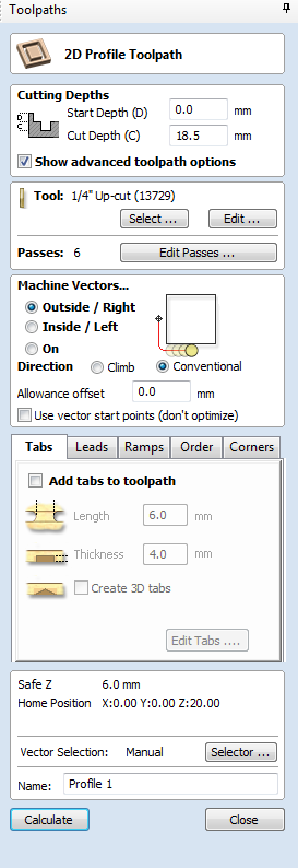
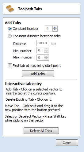
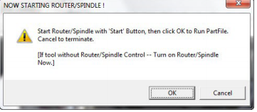
For Setting up the machine, ShopBot Documentation is all you need. It would only get repeative if I start going through it here. So I'm not.

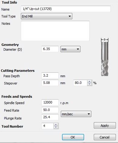
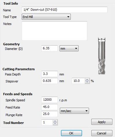
More details here on Feeds and Speeds Details

Chip load is a function of three different parameters: feed rate, RPM, and number of flutes on the tool.
Chip load is the thickness of the chunk of material taken by a tooth of the cutter. This is determined by how fast the cutter is moving forward into the material and how fast it is turning,
Chip load = Feed Rate / [RPM x number of flutes]


Following is a screenshot from the documentation.

Machine Setup

Here are the setups I followed when making my test cut.

Switched on the control box, then opened the Shopbot 3 application. Its better to leave the spindle disengaged to be on the safer side.

Click on the move tool, it should give a UI similar to the below image. Use the joysticks on the UI to move the spindle to set the origin. First set the x-y position and click the zero axes button, you will see a pop up with checkboxes for all three axes. Select the x and y axes and click ZERO.


At this point, we have our x and y axes set to origin, now we need to set the z-axis. Use the plate on the spindle head to set the origin for z-axis. Make sure the Input lights up when making contact with the aligator clip. After that click the z-axis button and place the plate on the bed, bottom to the drill bit. The prompts the come when using this feature; accordingly operate the prompts.


Now we have our origin set. Click Cut Part and select the .sbp file we want to cut.

We used Rhino to create our test cut, and import the .dxf file on Vcarve Pro, an application that sets the machine toolpath and spindle and feed rates. I took the screenshots for the tool settings when cutting my design, so check out that.

Test Cut

Milling the test cuts,


So accordingly I used this tolerance of 0.4mm on my designs. Since I need 18mm designs, I actually designed with 17.6mm. For 12mm, I was 11.5mm

Cycle Rack

Designing

As part of building something BIG, I decided to build a cycle rack. I used Rhino for designing. I also tried out Grasshopper a bit to try to make it parametric.


My opinion of Grasshopper is that, its similar to Antimony in many ways such as the UI and logic structure, and that we can use Grasshopper to build smooth curves and complex designs and make that parametric. I did not find a means to apply mathematical alogrithms for building shapes; that feature could be there but I failed to encounter it. Also I found replicating same parameters and joining these shapes pretty manual and making grasshopper visual logic unnecessarily complex. Also I had to manually extrude each shape (I reverted back and stopped working with Grasshopper, clearly at this point I found Antimony a lot easier). It only took me half of the time I invested for designing in Grasshopper, for the same design in Antimony. I continued working with Rhino and completed my design with limited help using Grasshopper.

For me the viewport is more advance in Rhino than in Antimony. I found it difficult to place points in one single plane. Because the viewport being so flexible, manual placing of points in one plane is tricky and the point may actually end up being in a different plane parallel to the plane we intended.

The final design,


I then nested layout the parts for cutting and exported it in .dxf format,


My design files

SkinnedCycleRack.3dm
SkinnedCycleRack.dxf
CycleRackMainSheet.dxf
CycleRack1st.dxf
CycleRack2nd.dxf

Tool settings

For setting the job toolpath, use the Job Setup window in Vcarve Pro, set the thickness of the material and since I didn't want the offset when cutting, I deselected it. And verified all the remaining details and proceeded to ok.


Make sure all the lines and vector paths of an object is joined. Select an object, and use the toolpath window to set the toolpath for the job. Add tabs to the toolpath, so that the parts dont move when cutting.


The following screenshots show the difference in the settings for 1/4 inch up-cut and down cut tool. I used the former one, which gives a cleaner cut at the bottom.


After setting the origin close the move controls. Click Cut Part and select the .dxf file and click Start button. It will show the a pop up with the spindle speed; note the rpm of the spindle is the same as that shown in the pop up window before proceeding.


The spindle rpm is shown on the control box display panel. After verifying press the green button (Start) on the Alpha and Buddy models. The blue button is the RESET and dongle is Emergency Stop. Note once you press the dongle to emergency stop, the job cannot be resumed and to resume you should have saved the origin points before setting coordinates as 0. Or use the space bar for temporarily stopping which you still could resume the job.


The spindle will move towards the origin and then start cutting your design based on that origin.

I was able to cut two of the remainder parts that could not be accomodated on the my allotted sheet first, by cutting it from the remains of others work.

I did have troubles assembling, some of the parts could not be assembled. I had cut some portions out to make it fit. I knew I would have troubles assembling even I designed. I though I could flex the legs of the board to assemble. But it turned out to be stiff and strong. I used the 18mm plywood for this project.


Milling and Cutting

During the milling process, I took couple of photos. Its important to be cautious and careful when doing the same beside the shopbot.


My Cycle Rack after assembling, Hero Shots