This week's assignment was to program my echo board build in week 6. For this I started of reading the datasheet for 8 bit Atmel microcontroller.
I was unable to identify which all data from the datasheet I should be looking for. So I went through a couple of tutorials to figure out the basics of Embedded programming using C. Link to a tutorial.
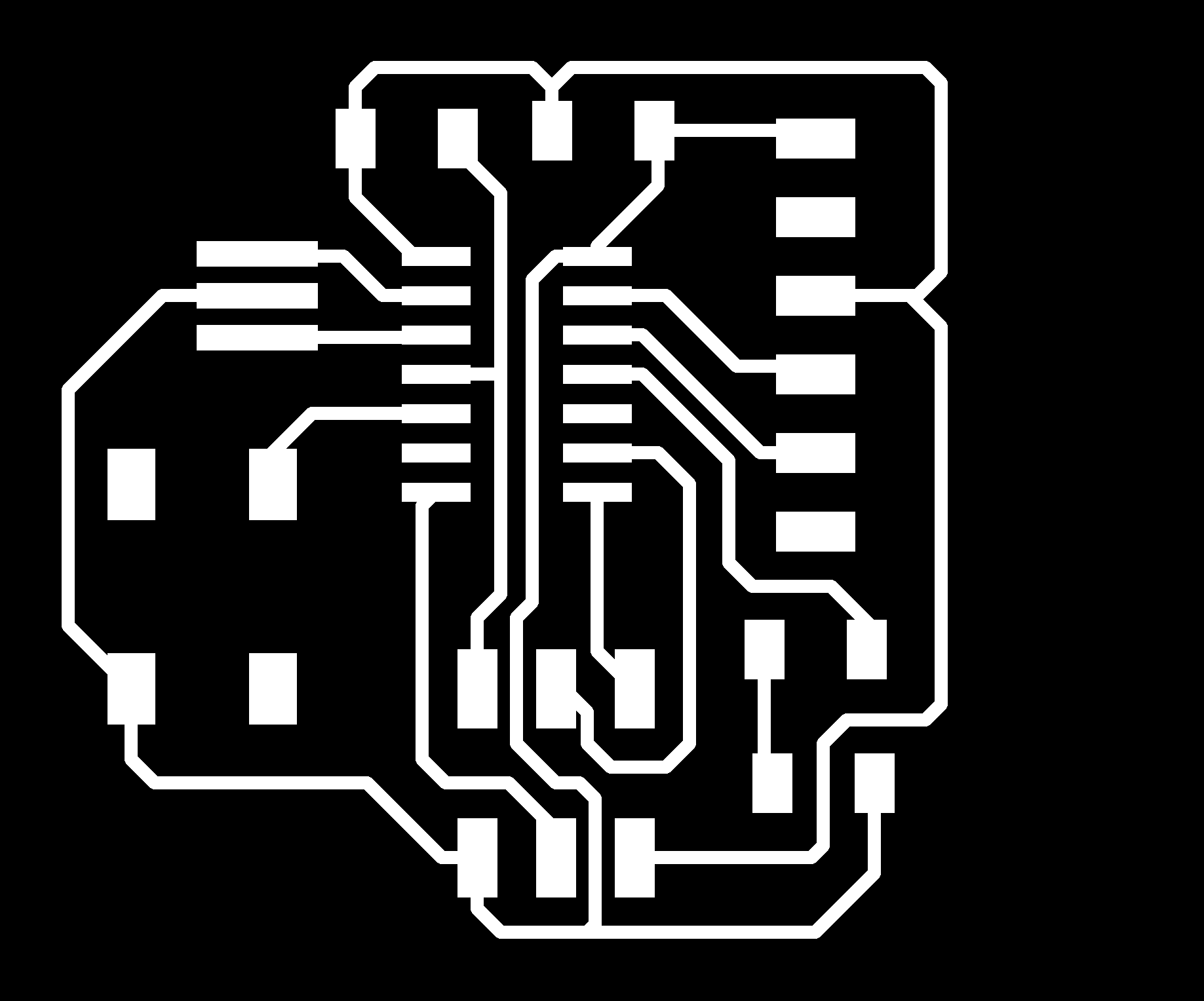
With this I was able to understand the basics for programming in AVR-C. But that alone could not be useful without the my board design. Below is the schematic diagram of my echo board.
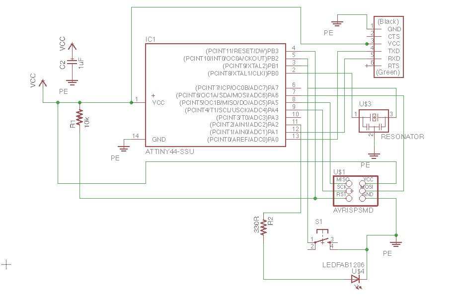
I identified the input port would be PORTB2 and output to be PORTA2 from my schematic diagram. I was able to write a couple of programs to blink the led on my board.
blink.c
#include < avr/io.h >
main(){
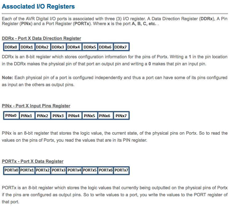
DDRA |= (1<<2);
DDRB &= (!(1<<2));
PORTB |= (1<<2);
while(1){
if(!(PINB & (1<<2))){
PORTA |= (1<<2);
}
else{
PORTA &= (!(1<<2));
}
}
}
I wanted to try out lighting led with a delay of 1 sec. Also I noted that the clock frequency for ATTiny44 is 20MHz from the datasheet.
delay.c
#include < avr/io.h >
#define F_CPU 20000000
#include < util/delay.h >

main() {
    DDRA = 0xFF;
    while(1) {
        PORTA |= (1 << 2);
        _delay_ms(1000);
        PORTA &= (!(1<<2));
        _delay_ms(1000);

    }
    return 0;
}
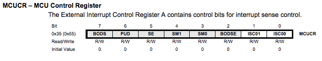
I tried out interrupts. My intention was to light the led on a delay, same as the above code, but also the light it, when I press down the button and go back to the delayed sequence when I let go on the switch. I used the following registers to
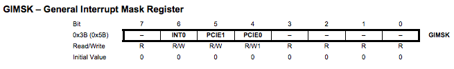
An interrupt vector is the memory address of an ISR, Interrupt Service Routine, and apart of the microcontroller's program memory. As such when utilizing interrupts this section of memory should be reserved to store pointers to interrupt handlers and not to store regular programs. The interrupt vector for each interrupt provided by ATtiny44 found from the datasheet.

interrupt.c
#include < avr/io.h >
#define F_CPU 20000000
#include < util/delay.h >
#include < avr/interrupt.h >
int pause = 0;
ISR(INT0_vect){
//interept service routine while interept is made by int0 pin
if (!(PINB&(1<<2))) { // if PB2 is low
pause = 1;
PORTA|=(1<<2); // set PA2 High
}
else{ // else
PORTA&=(!(1<<2)); // set PA2 Low
pause = 0;
}
}
main(){
DDRA=0xFF; // set PA0 to PA3 as output
DDRB=0x0; // set PORTB as input
PORTB|=(1<<2); // pullup PB2
pause = 0;
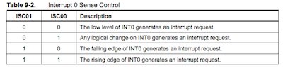
MCUCR = 1 << ISC00 ; // Any logical change on INT0 generates an interrupt request.
GIMSK|= (1 << INT0); // external pin interrupt is enabled on INT0 pin
sei(); // set global interrupt flag
while (1) {
// simply nothng
if (pause == 0) {
PORTA |= (1 << 2);
_delay_ms(1000);
PORTA &= (!(1<<2));
_delay_ms(1000);
}
}
return 0;
}
This above could works fine for interrupts duration lesser than 1 sec. But if I press on the switch more than that, it is found that the control doesnt seem to go back to the main program. That is, after a long interrupt, the delay sequence is not working. I accidently damaged my board, when trying to debug this issue.
Attached the Makefile I scraped from Neil's and accordingly change the name of the file you want to run. Run man avrdude to access the manual for avrdude.
program-usbtiny-fuses: $(PROJECT).hex
    avrdude -p t44 -P usb -c usbtiny -U lfuse:w:0x5E:m
The above was changed to the following, because the led was blinking rather fast. The delay was small. Found the lfuse setting was wrong.
program-usbtiny-fuses: $(PROJECT).hex
    avrdude -p t44 -P usb -c usbtiny -U lfuse:w:0xDE:m
Following pictures show the board running interrupt.c


Original design files
EchoCut.png
EchoCutInverted.png
EchoTraces.png
EchoSchematic.brd
EchoSchematic.sch