Electronics Design

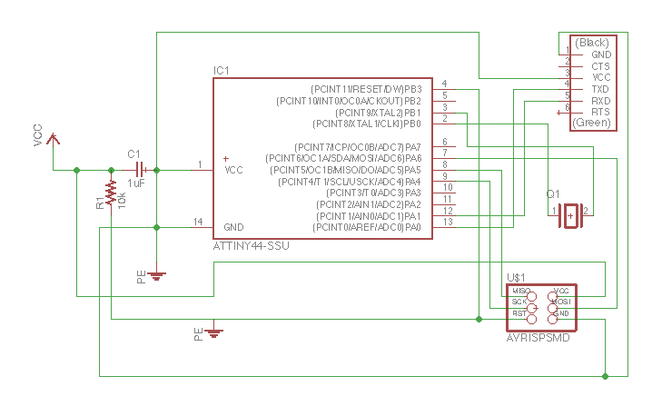
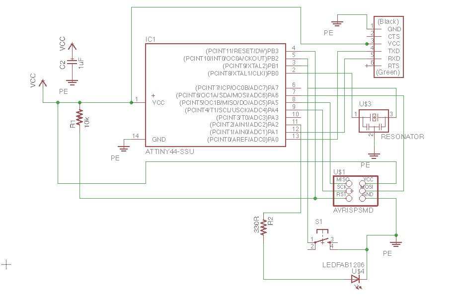
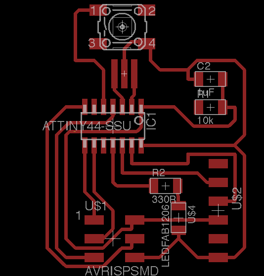
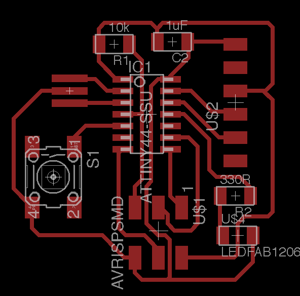
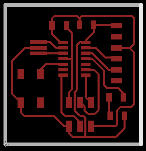
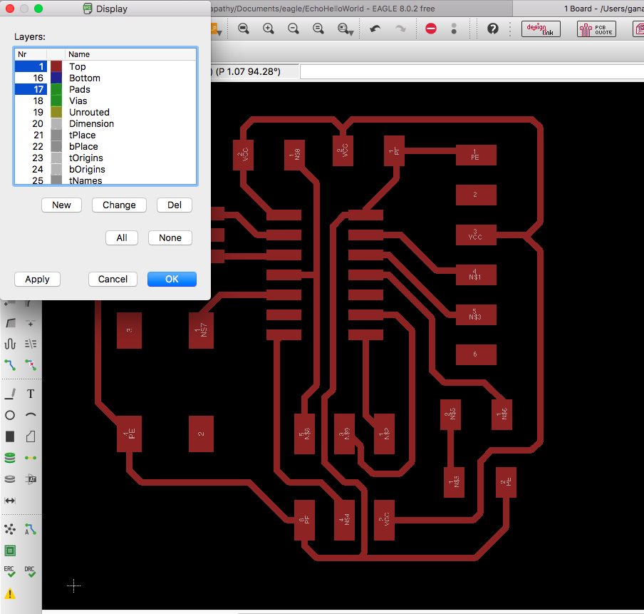
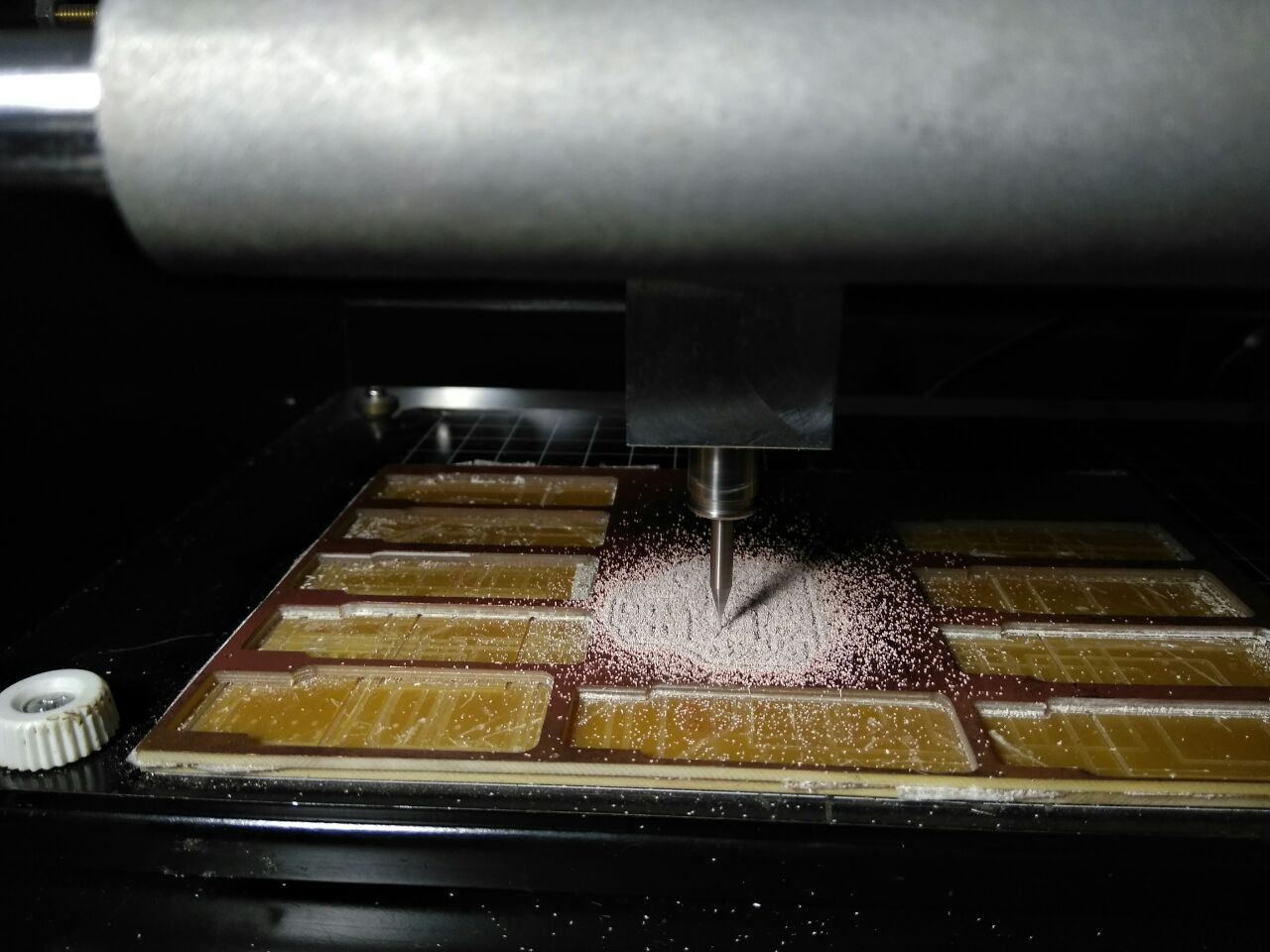
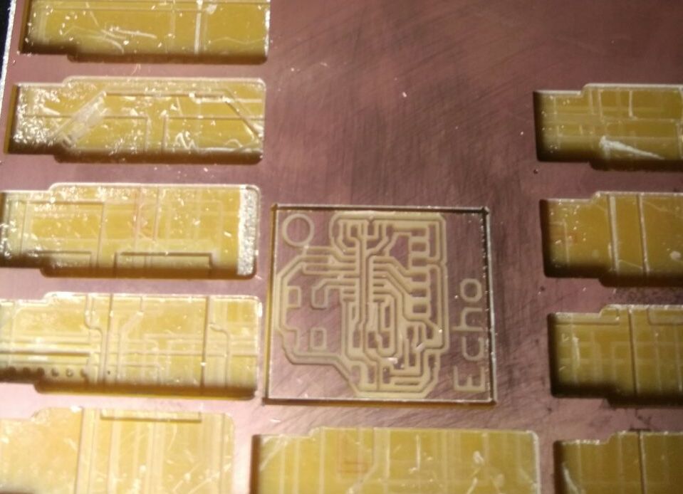
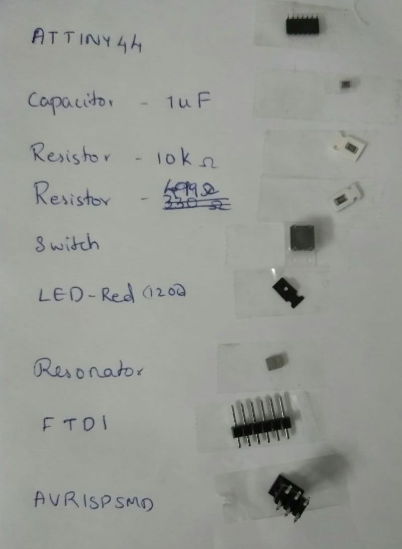
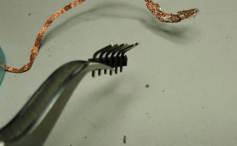
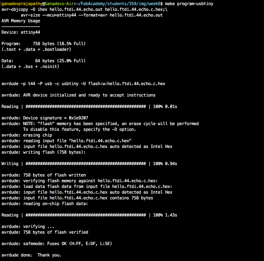
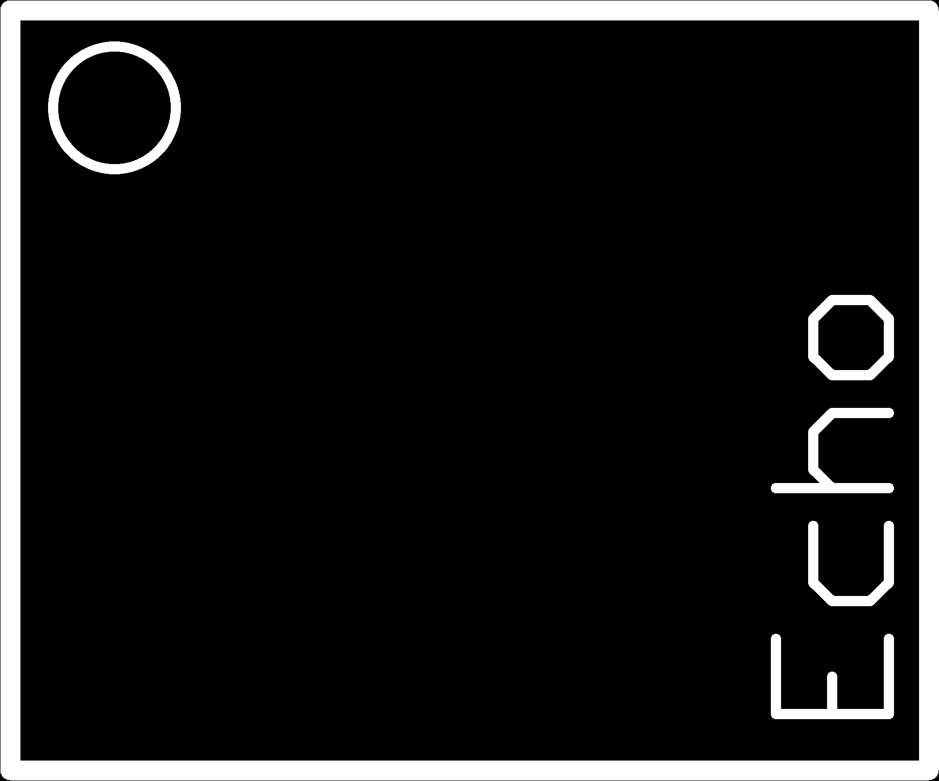
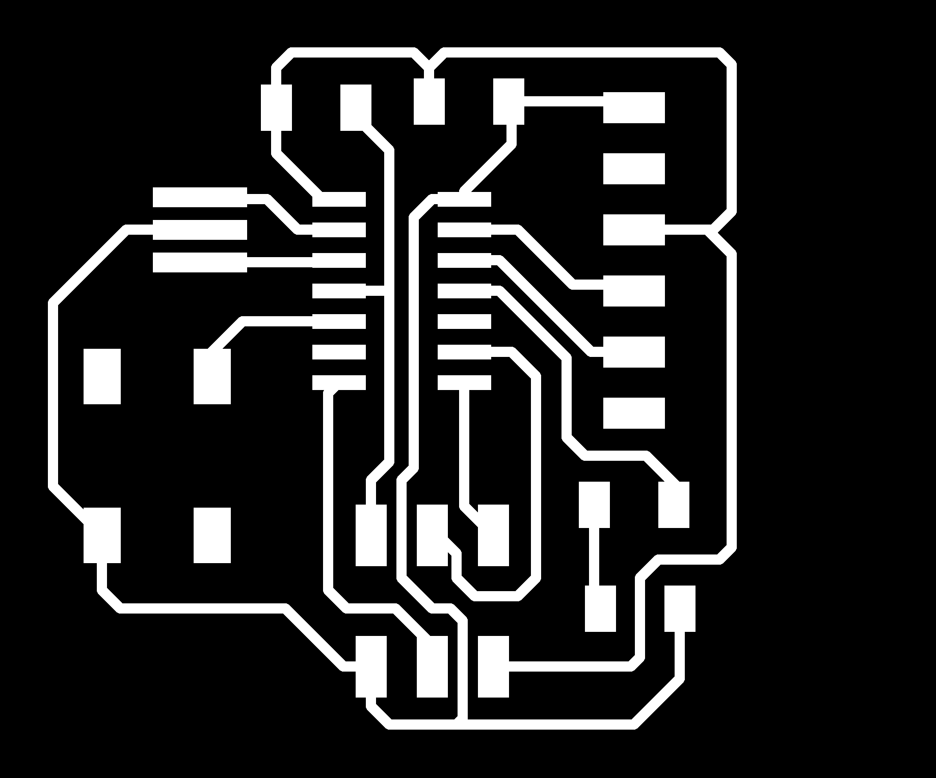
This weeks assignment was to redraw the Echo Hello World Board. Along with that we need to add an LED with a current limiting resistor and a button also.

Electronics Fundamentals

To get started, our instructors gave us an introduction to the basic fundamentals of Electronics.

Current (I) is a flow of electricity which results from the ordered directional movement of electrically charged particles.
Voltage (V), also called electromotive force, is a quantitative expression of the potential difference in charge between two points in an electrical field. It can be direct or alternating.
Resistance is an electrical quantity that measures how the device or material reduces the electric current flow through it. The resistance is measured in units of ohms (Ω). If we make an analogy to water flow in pipes, the resistance is bigger when the pipe is thinner, so the water flow is decreased.

One volt will drive one coulomb (6.24 x 10¹⁸) charge carriers, such as electrons, through a resistance of one ohm in one second.

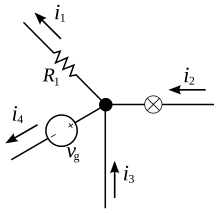
Kirchhoff's current law
The principle of conservation of electric charge implies that:
At any node (junction) in an electrical circuit, the sum of currents flowing into that node is equal to the sum of currents flowing out of that node. The algebric equation for the following diagram would look like, i2 + i3 = i1 + i4


Ohm's Law
Ohm's law states that the current through a conductor between two points is directly proportional to the voltage across the two points. Introducing the constant of proportionality, the resistance; where
I is the current through the conductor in units of amperes,
V is the voltage measured across the conductor in units of volts, and
R is the resistance of the conductor in units of ohms.

Faraday's Law
The induced electromotive force in any closed circuit is equal to the negative of the time rate of change of the magnetic flux enclosed by the circuit.

where is the electromotive force (EMF) and ΦB is the magnetic flux.

-- Wikipedia.

Electronic Components

Active and Passive components
Active electronic components are those that can control the flow of electricity. Some examples of active electronic components are transistors, vacuum tubes, silicon-controlled rectifiers.
Passive electronic components are those that don’t have the ability to control current by means of another electrical signal. Examples of passive electronic components are capacitors, resistors, inductors.

Transistors
A transistor is a device that regulates current or voltage flow and acts as a switch or gate for electronic signals. Transistors consist of three layers of a semiconductor material, each capable of carrying a current. A voltage or current applied to one pair of the transistor's terminals controls the current through another pair of terminals. Because the controlled (output) power can be higher than the controlling (input) power, a transistor can amplify a signal.

BJTs vs FETs
How it operates BJTs FETs
BJTs are current-controlled. They require a biasing current to the base terminal of operation. FETs are voltage-controlled. They only require voltage applied to the gate to turn the FET either on or off. They do not require a biasing current for operation.
Input Impedance BJTs offer smaller input impedances, meaning they draw more current from the power circuit feeding it, which can cause loading of the circuit. FETs offer greater input impedance than BJTs. This means that they practically draw no current and therefore load down the power circuit that's feeding a lot less and minimimally.
Gain
(Transconductance)
BJTs offer greater gain at the output than FETs. The gain (or transconductance) of FETs are smaller than for BJTs.
Size BJTs are larger in size and therefore take up more physical space than  FETs normally. FETs can be manufactured much smaller than BJTs. This is especially important for integrated circuits that are composed up of many transistors.
Popularity BJTs are less popular and less widely used FETS are definitely more popular and widely used in commercial circuits today than BJTs
Cost BJTs are cheaper to manufacture FETs, especially MOSFETs, are more expensive to manufacture

Detailed explanations are provide in this link

Operational Amplifier
An operational amplifier (often op-amp or opamp) is a DC-coupled high-gain electronic voltage amplifier with a differential input and, usually, a single-ended output. In this configuration, an op-amp produces an output potential (relative to circuit ground) that is typically hundreds of thousands of times larger than the potential difference between its input terminals. Wiki Link.

Pull-up / down Resistors
With a pull-up resistor, the input pin will read a high state when the button is not pressed. In other words, a small amount of current is flowing between VCC and the input pin (not to ground), thus the input pin reads close to VCC. When the button is pressed, it connects the input pin directly to ground.

You will find more details and explanations here
A pull-down resistor works in the same way but is connected to ground. It holds the logic signal near zero volts when no other active device is connected. The value of a pull down or pull up resistor will vary depending upon your specific devices involved.

Filter Capacitor
A filter capacitor is a capacitor which filters out a certain frequency or range of frequencies from a circuit. Usually capacitors filter out very low frequency signals. These are signals that are very close to 0Hz in frequency value. These are also referred to as DC signals. When for some reason voltage drops, capacitor acts to stabilize the voltage. Capacitor doesn't allow sudden change in voltage.

More details

Inductor
Inductor is a passive two-terminal electrical component that stores electrical energy in a magnetic field when electric current is flowing through it. An inductor is characterized by its inductance, which is the ratio of the voltage to the rate of change of current.

Microprocessors and Microcontrollers
A microprocessor generally does not have RAM, ROM and IO pins. It usually uses its pins as a bus to interface to peripherals such as RAM, ROM, Serial ports, Digital and Analog IO. It is expandable at the board level due to this.
A microcontroller is 'all in one', the processor, ram, IO all on the one chip, as such you cannot (say) increase the amount of RAM available or the number of IO ports. The controlling bus is internal and not available to the board designer.
This means that a microprocessor is generally capable of being built into bigger general purpose applications than a microcontroller. The microcontroller is usually used for more dedicated applications.

Know more about Microcontroller Architecture.
Datasheet for ATTINY44A-SSU-ND

Schematic designing

For redrawing the Echo Hello World board, I started with Eagle to create the schematic drawing for the same.
I downloaded and and installed the mac version for Eagle; and created a new project. The layout for toolset in Eagle is that there is a textbox on the top toolbar that would let you write commands for the tools or you could use the toolbar on the left and select the icons for current operation. The screenshot indicates the command textbox.


Ran Add. Found out no libraries where linked.


I downloaded the fab.lbr library for Eagle; and placed it within the Eagle's lbr directory. Clicked the use button and selected the fab.lbr from the list of lbrs. The screenshot shows after selecting fab.lbr


Selected the ATTiny thats available at our FabLab, ATTINY44-SSU, from fab.ldr and similarly selected all the components I wanted to recreate the Echo Hello World board. I used the following image to recreate my schematic diagram. The next screenshot is the one I created. The commands I used were net, delete, show, move


As this week's assignment requires me to connect an LED and a push button, I updated the schematic diagram accomodating both.


I found the resistance value of the current limiting resistor for the LED. I used the datasheet to find the voltage (1.8 V), the test current (10 mA). The resistance was found to be 330 ohms but since our FabLab doesnt have that kind of resistor, I had to use the 499 ohm resistor.

PCB Layout designing

After completing the schematic diagram, clicked switch to board. Check the Design rules. Most of the width was 8mil, but our drill bit size is 16mil.


So accordingly changed wherever set wrong.


The schematic diagram creates nodes (components) and links (their connections) for us to create the layout. We start with the following


We can drag the components and redraw the connections with drill bit thickness, but along with that we also need to make sure we follow the design rules. I used the auto-route feature to create my layout the first time.


The tool provided some connection layout suggestions based on the layout of the components. There were some 100% successfull layouts which follow the design rules.


I decided to manually redraw the connections and layouts. The problem with most of these trial not working out is that there will be at least one intersection happening. Either I had to use a 0k resistor to jump over these unwanted intersections or rearrange the position of the components. After many trial and errors, and many connection rip ups


I was able to create a successful design that checks up with the design rules.
Screenshot of my Echo Board design.


Exporting pngs

For cutting the board outline, we need the line thickness to be that of the drill bit. So we need to go to the properties of the outline and change the width to the thickness of the drill bit, which in my case is 1/32 of an inch.


To export, we can use the layers tool to select the set of layers we want to display and export. For displaying only the outline, I selected Dimension. I used the Text tool to make a writing and increase the size of the word. I also had to change the text to vector so that the design follows the design rules. And then I changed the layers to the vector text to Dimension layer.


I then exported it in png format with a resolution of more the 1000 dpi and in monochrome. This will be my milling outline.

I then went on to export the mill traces for the echo board by the same above procedure but with the Top and Pads layers.


Original design files

EchoCut.png
EchoCutInverted.png
EchoTraces.png
EchoSchematic.brd
EchoSchematic.sch

PCB Milling and Assembling

Some of my collegues here at the fablab tried out Fab online modules, and they had some troubles; the machine acted in unexpected ways, broke couple of bits, and it is dependent on our internet connections; these problems forced us to migrate towards more reliable local fab modules.
After milling and cutting,


Collected the following components,


Assembling the components, I had to bend the FTDI pins, because I did not think through when I added "Echo" text on to the PCB.


My Echo Board,


Programming

Our instructor, Yadu, created blink.c to detect button click and lights up the LED. I was able to burn the code into the IC.


Couple of pictures showing led light on button click.