Vibrating motors
For this week assignment I considered moving steps forward my final project development,
getting to know output devices world.
Starting from the list
Neil provided us, I decided to start with DC
vibration motors. I decided not to follow "replicating Neil's job" path, instead
I preferred to start from output devices' characteristics to understand components I would have needed for a minimal circuit.
I really wanted to make acquaintance with
vibrating motors
because I'll soon have to work with it for my final project. Moreover, I wanted to know how can you control
working processes of such a tiny motor without using a motor driver.
Minimal Arduino circuit
In my lab I found Groove starter kit vibrating
motor module and I simply desoldered it so as to use it for my PCB.
To start with, I had a look at some tutorials about this kind of output device and
this one
really seemed clear and complete to me. The example was a minimal circuit made for Arduino and it included:
- Arduino board;
- a vibration motor;
- 1N4001 Diode;
- 0.1µF ceramic capacitor;
- 1KΩ Resistor;
- 2N2222 NPN Transistor;
- USB connector
I highlighted the main components cause each one has a fundamental role that is of primary importance to
solve components parallel and series connections and my first intention was to understand WHY those
components were necessary and were placed precisely like that :
1- TRANSISTOR: this component's importance stays in that it has to provide the motor a proper current,
not too high, not too low; in fact, the vibration motor needs a minimum of current to work ( around 75mA )
but too much current could damage it seriously, therefore, the transistor takes Vin (input voltage) from
Arduino output pin (G 1 line of the transistor) and sends it to the motor (D 2 line)
or to ground (S 3 line) if it is too high.
2- DIODE:the diode, together with the capacitor, is linked in parallel to the motor
and they both act as "security measures"; in fact, the diode lets the current flow in a direction only
and this prevents the passage to possible current flows generated by motor working process. Therefore, it better
to use an higher DC-blocking-voltage diode than a lower one (which risks to be burnt by high voltages - remember:
I ∝ V from OHM's law).
3- CAPACITOR:this component accumulates charges of current coming from the output pin and
gradually hands it to the motor; consequently, it better not to use a high-capacity capacitor because it would loose
current off too slowly to make the motor working.
From Arduino to ATtiny 44 circuit
Anyway I had to substitute some components it with ATtiny44 to which I also had to link a AVRISP and FTDI connectors.
As for the diode and the transistor, it required me more time to understand how could I replace them with components I had in my lab.
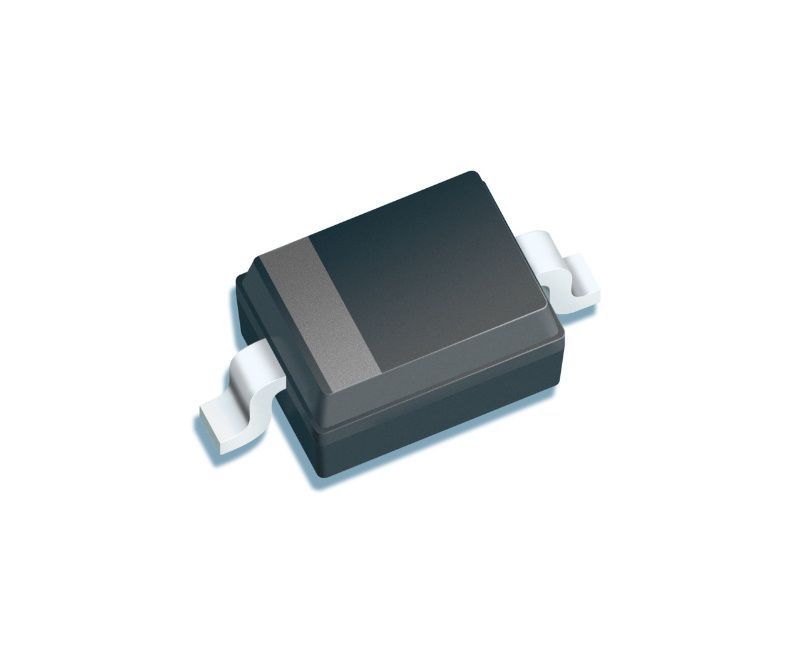
DIODE
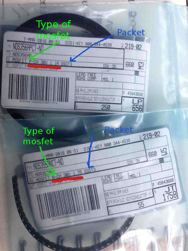
The circuit I took as an example used a 1N4001 diode but to know its main characteristics I had a look at its
datasheet. The most important one I had to care for
was VRRM which regarded reverse current that the motor may produce.
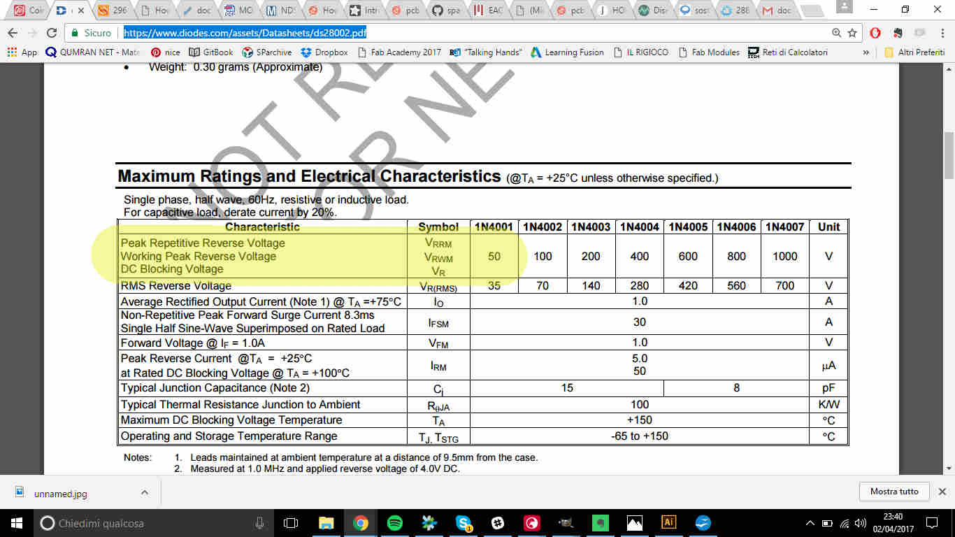 Looking into the drawers around me I could only find 30V VRRM
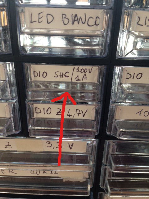 Despite being the example diode VRRM higher, using a 30V one wouldn't compromise my board functioning
(it is really unlikely that reverse motor current can reach up to 30V) and I could take 1A
diode because my coin motor needed around just 75 mA.
Despite being the example diode VRRM higher, using a 30V one wouldn't compromise my board functioning
(it is really unlikely that reverse motor current can reach up to 30V) and I could take 1A
diode because my coin motor needed around just 75 mA.
TRANSISTOR & MOSFET
As for the transistor, things got complicated a bit, also due to my little electronics knowledge.
In the example, they used 2N2222 transistor
but I had none in my lab...actually I couldn't find any transistor at all! I spent something like an hour
in seeking for any kind of that device without results, just because I had no clear ideas about the
difference between MOSFETs and TRANSISTORs.
Transistors look like (usually) 3-pin black tiny bricks and are divided in two big families: BJT
(Bipolar Junction Transistors) and MOSFETs. They both work
following the same principles but MOSFETs gave greater control abilities
whereas BJT are almost used like ON / OFF devices.
BJT
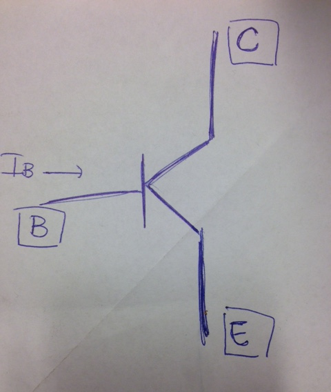 BJP are current amplifiers: according to IB value (current flowing in the base,
the current in C (collector) and E (emittor) is higher.
BJP are current amplifiers: according to IB value (current flowing in the base,
the current in C (collector) and E (emittor) is higher.
MOSFETs
First of all. let's start from the name:M O S F E T stands for metal–oxide–semiconductor
field-effect transistor. So being a FET transistor it uses an electric field to control
the electrical behaviour of the device. This component, believe it or not, it's really close to a sandwich:
 The P-silicon (either it can be N) level is a semiconductor which has been deprived /furnished of
electrons to increase conductivity. So, basically it is a transistor with improved skills and despite working
on a reference current it considers G (gate)'s voltage.
( Here you can find an example
of MOSFET datasheet and
here
others for many kind of MOSFET).
The P-silicon (either it can be N) level is a semiconductor which has been deprived /furnished of
electrons to increase conductivity. So, basically it is a transistor with improved skills and despite working
on a reference current it considers G (gate)'s voltage.
( Here you can find an example
of MOSFET datasheet and
here
others for many kind of MOSFET).
In my lab I found
 Now that I had a clearer idea about what I had around me on the table, I could solve my problem using a mosfet.
I was then ready to draw my board on EAGLE
Now that I had a clearer idea about what I had around me on the table, I could solve my problem using a mosfet.
I was then ready to draw my board on EAGLE
BRAINO Drawing
I had already used EAGLE before (see this link for basic tools explanation) but I was
running out of time to meet with a new software and also I wanted to make a more complicated board, so
I wanted to walk on already-blazed trails.
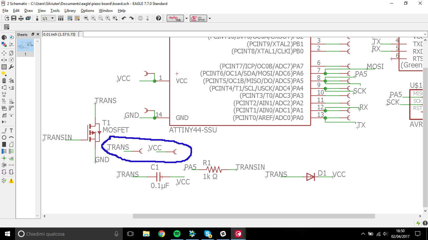
I easily added and link the components below:
- ATtiny44
- Mosfet
- Diode
- Capacitor
- Resisitor
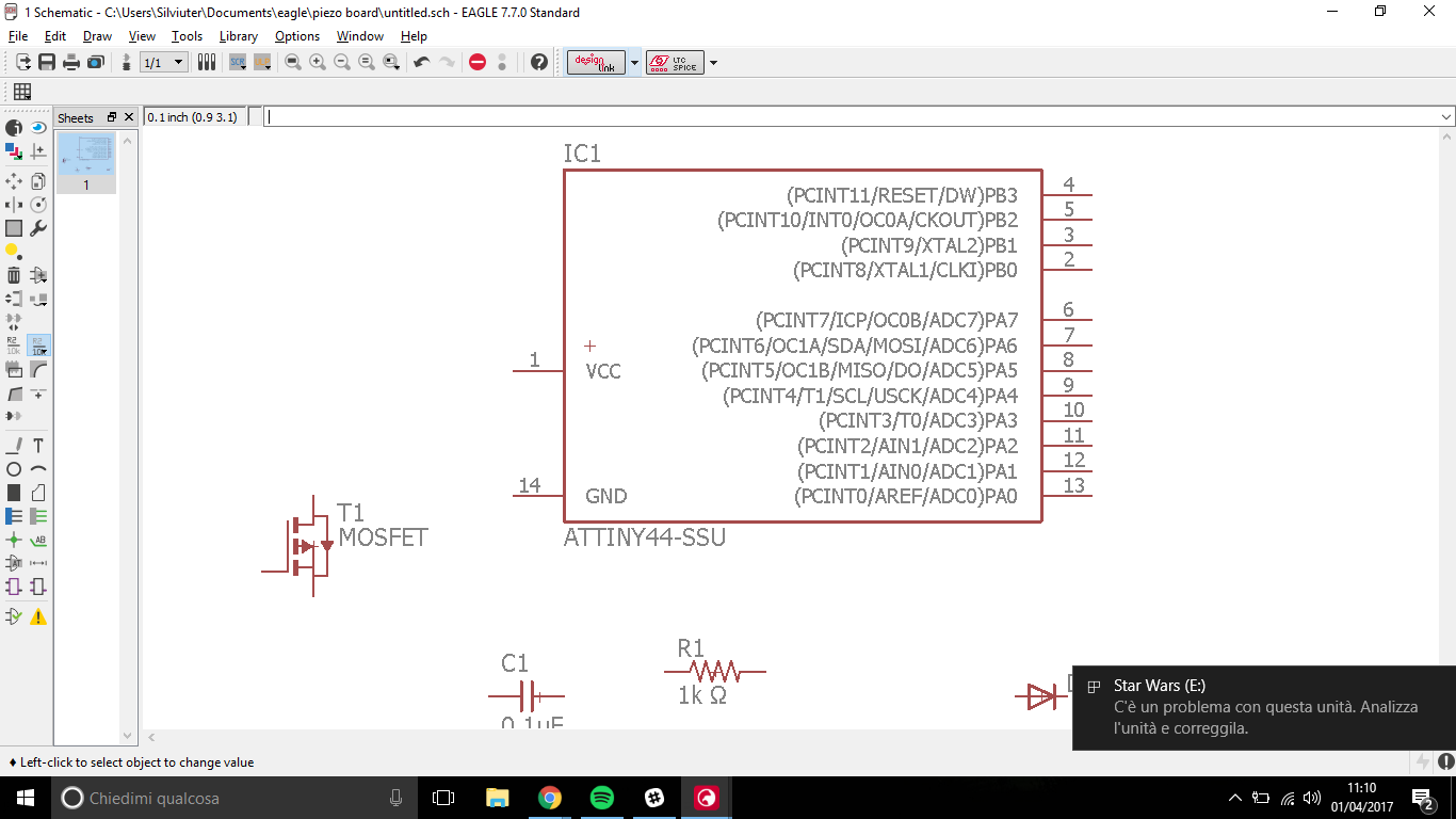 NB: to link the ATtiny44 to other components, I looked at pinout configuration on
the datasheet.
NB: to link the ATtiny44 to other components, I looked at pinout configuration on
the datasheet.
While linking all the pins I needed, I saw an obscure PWM acronym on the example circuit and I
wanted to discover what it could mean.
PWM: Pulse Width Modulation
Pulse Width Modulation is a
"method" to control some output device, deciding the percentage of time we want the signal to be high
or low, so basically it consists in set the duty cycle as desired. From microcontrollers' point of
view all this system refers to something like a timer, because they are told (via code) when
to set a pin high.
Little more about PWM and SoftwareSerial here
At this point, I wanted to make my board sewable, like Lilypad Arduino or
Flora boards, but I didn't know how to add holes in my schematic and I looked up in the internet
at
this,
this, this and
this tutorial but I didn't end up with a nice HOW-TO but I thought I could simply look
for Lilypad hole device in another library (fab.lbr hasn't them).
NB: notice that all devices in holes.lbr are mounting holes and
they're not conductive.
I then found this GitHub repo
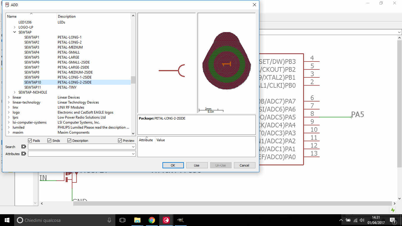
with two libraries and I found what I needed. Starting from Lilypad schematic I found info about pads I was looking for:
 ..and I searched for them in Lilypad library:
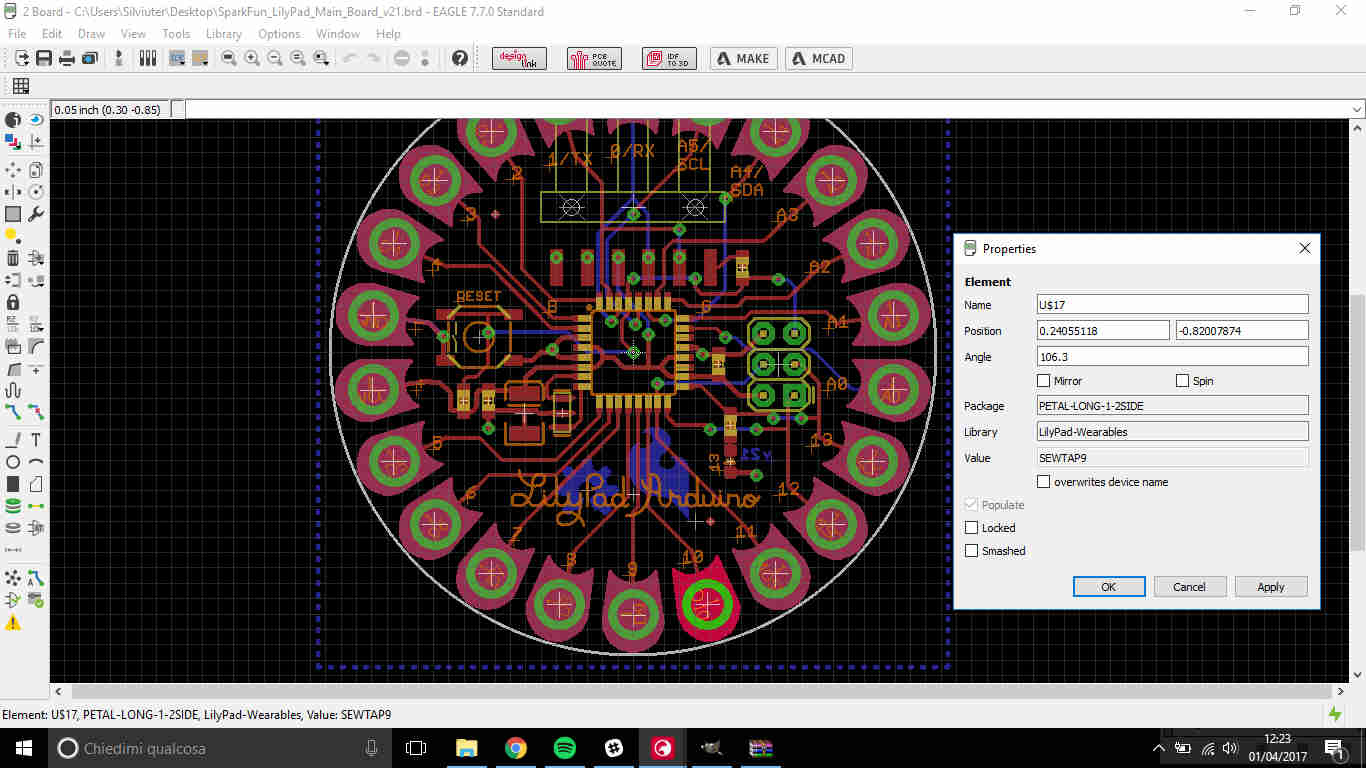
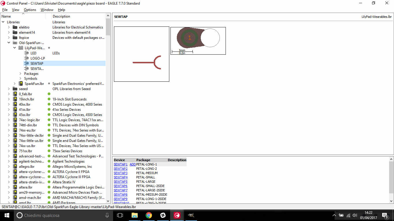 Seeming them too big for my board, I chose another type:
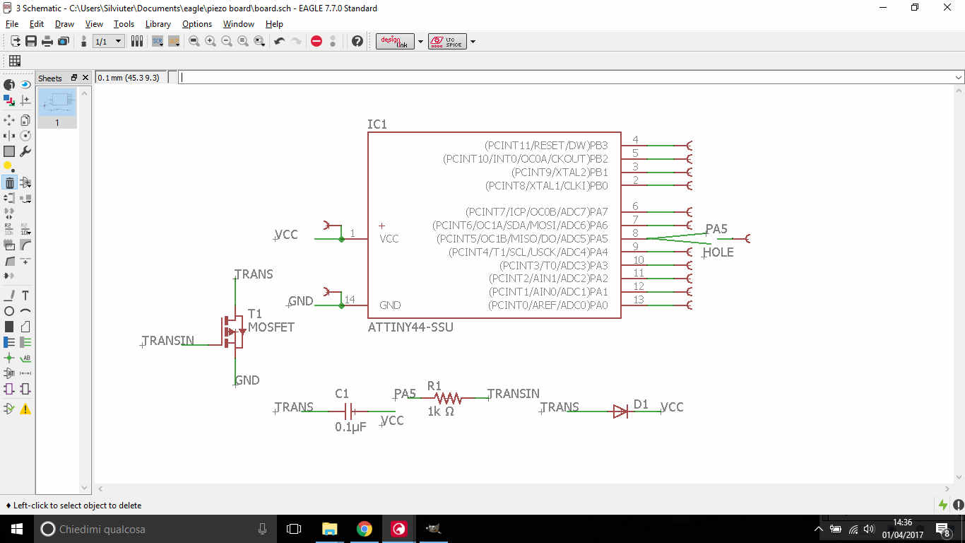
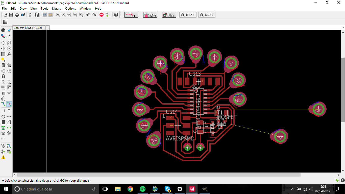
 I add one of them for each ATtiny pin:
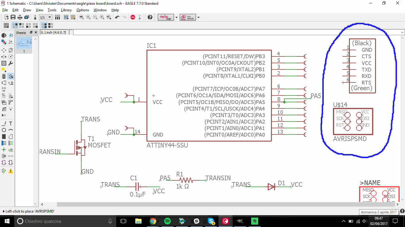
 I then added an ISP and FTDI connector ( I forgot I wasn't using an Arduino ;) )
 ...and also two through-all pads for my vibration motor
 I found it difficult to give SCK and PA5 pads a position but I realized that one of them (SCK) was linked to the ISP connector and, since its function is related to microcontroller clock, I needn't an outer pad for it and the other (PA5) was already connected to the motor.
 So i simply deleted them:
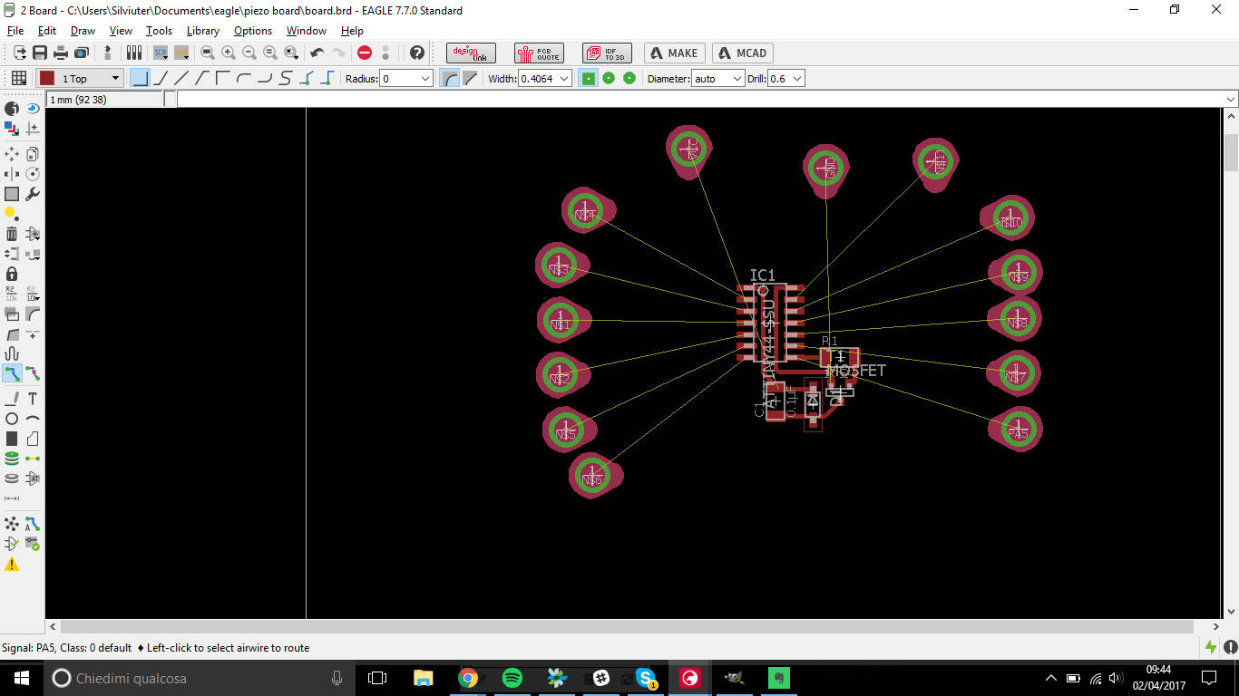
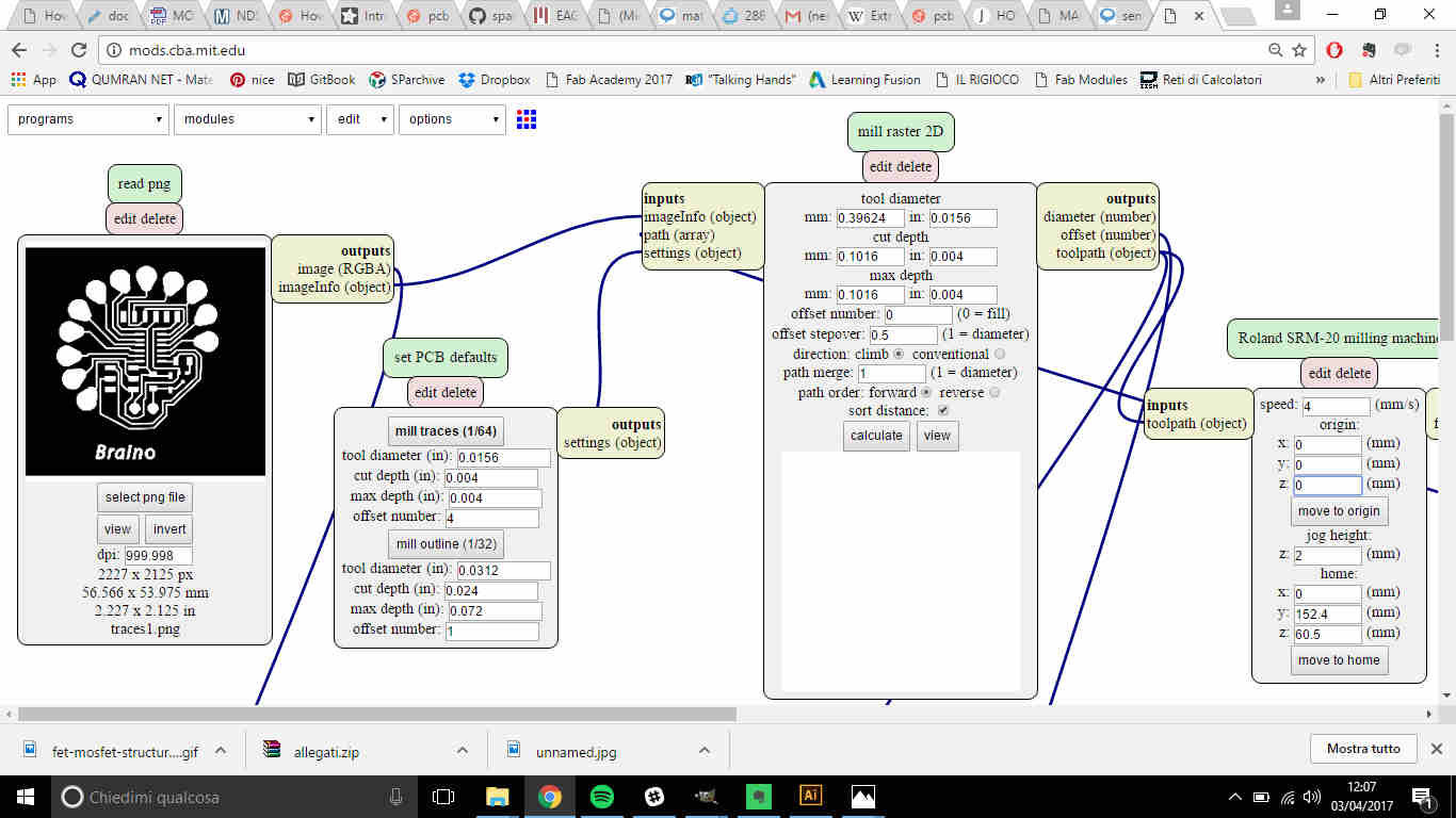
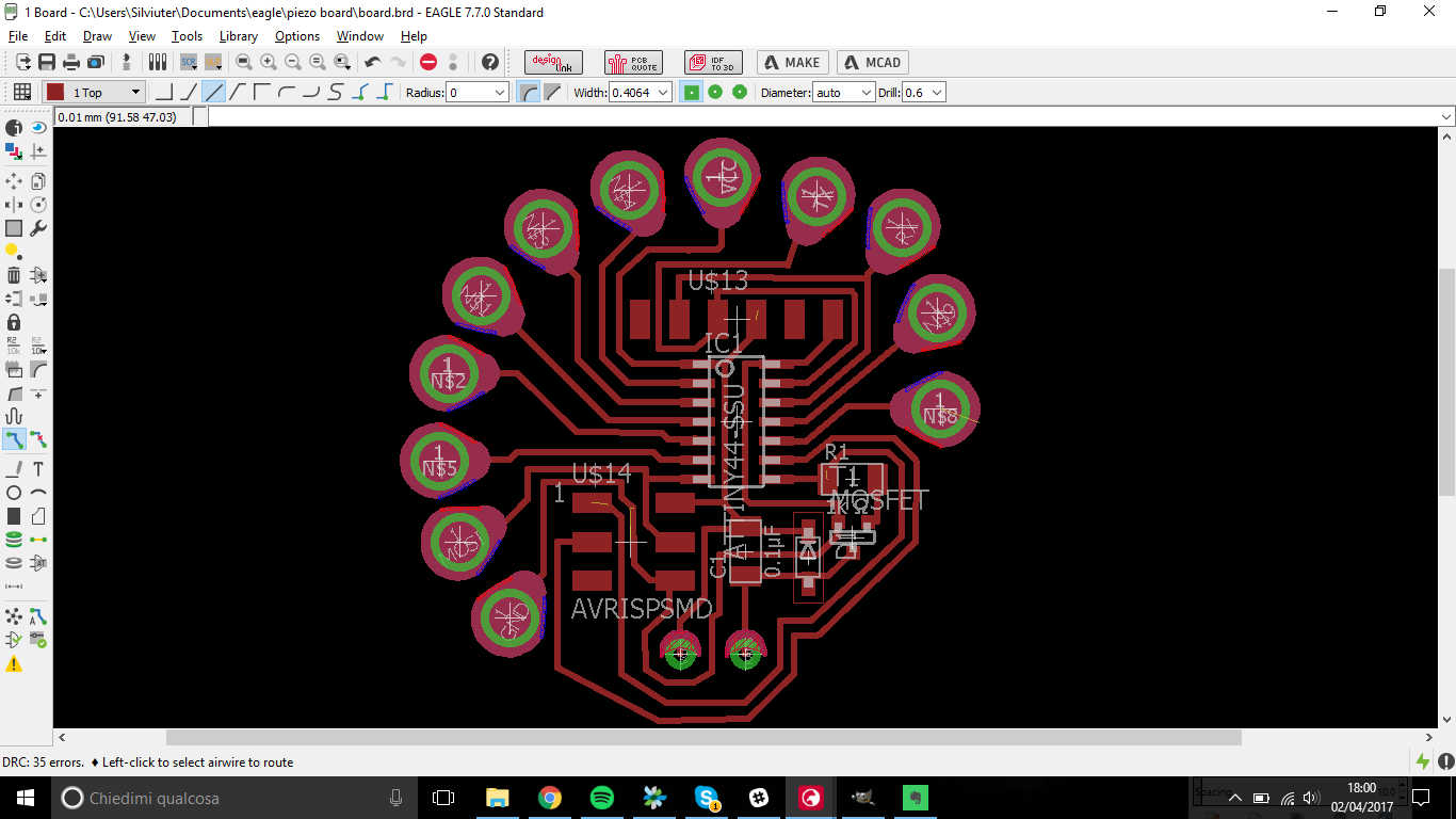 I selected Top, Pads and Vias layers and I exported it as Image (monochrome, 1000dpi).
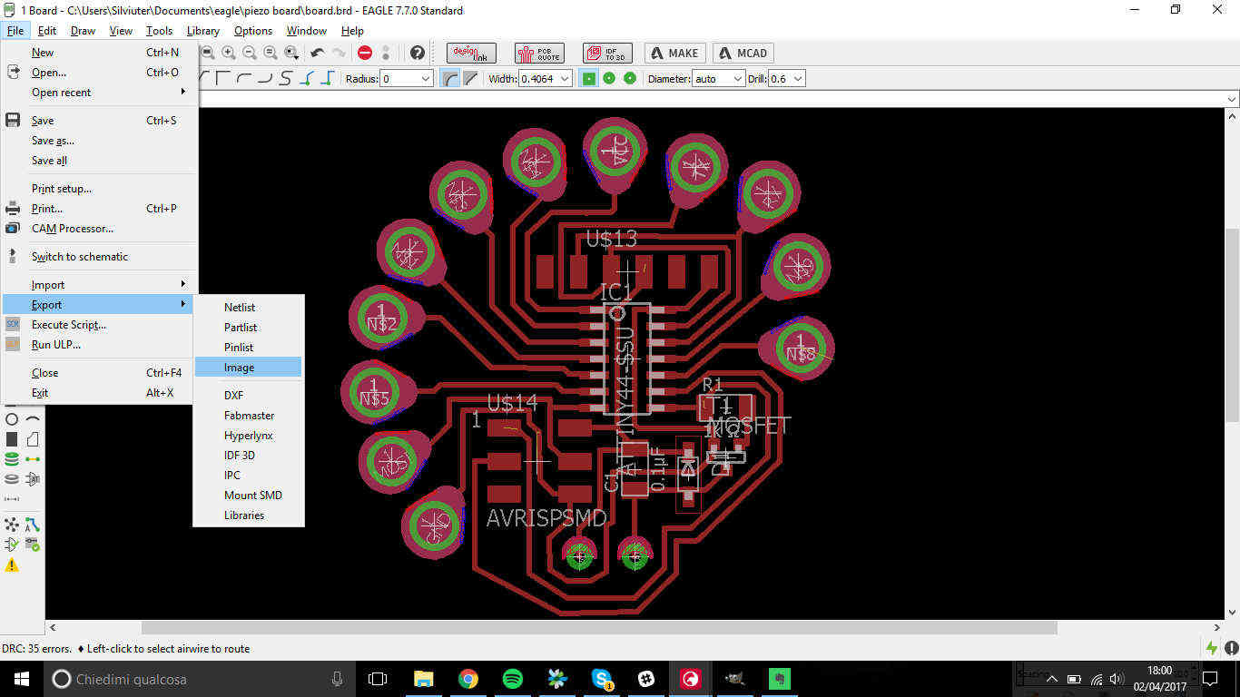 Now it was milling time...and the best is yet to come ;)
MILLING or LASERCUTTING? That's the question
As you'll soon see, the question received quick answer, I decided to use my lab's Trotec 400 Speedy Flex
to cut my board, because I never used for this before but also because Roland SRM-20 was playing against
my self control.
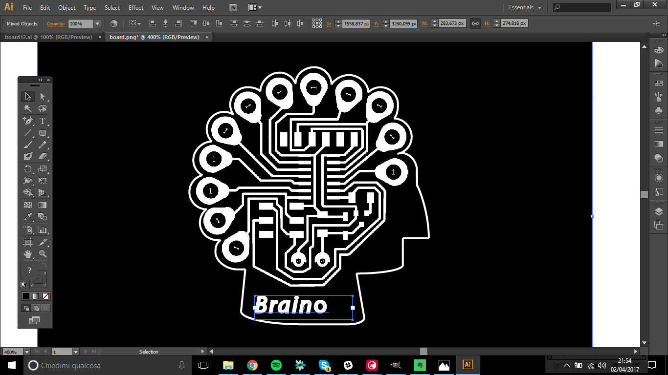
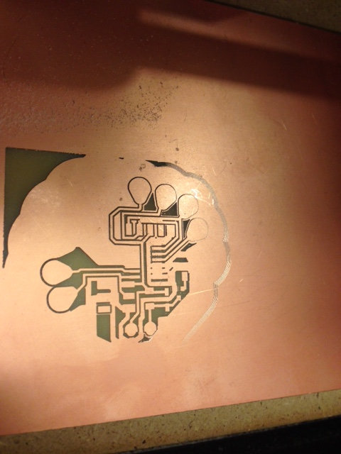
I had to define my board edges, being the shape quite strange, I caught the opportunity to imagine something it could
look like in real world.....and I saw it looked like an human brain! Hence, I gave it the name of Braino.
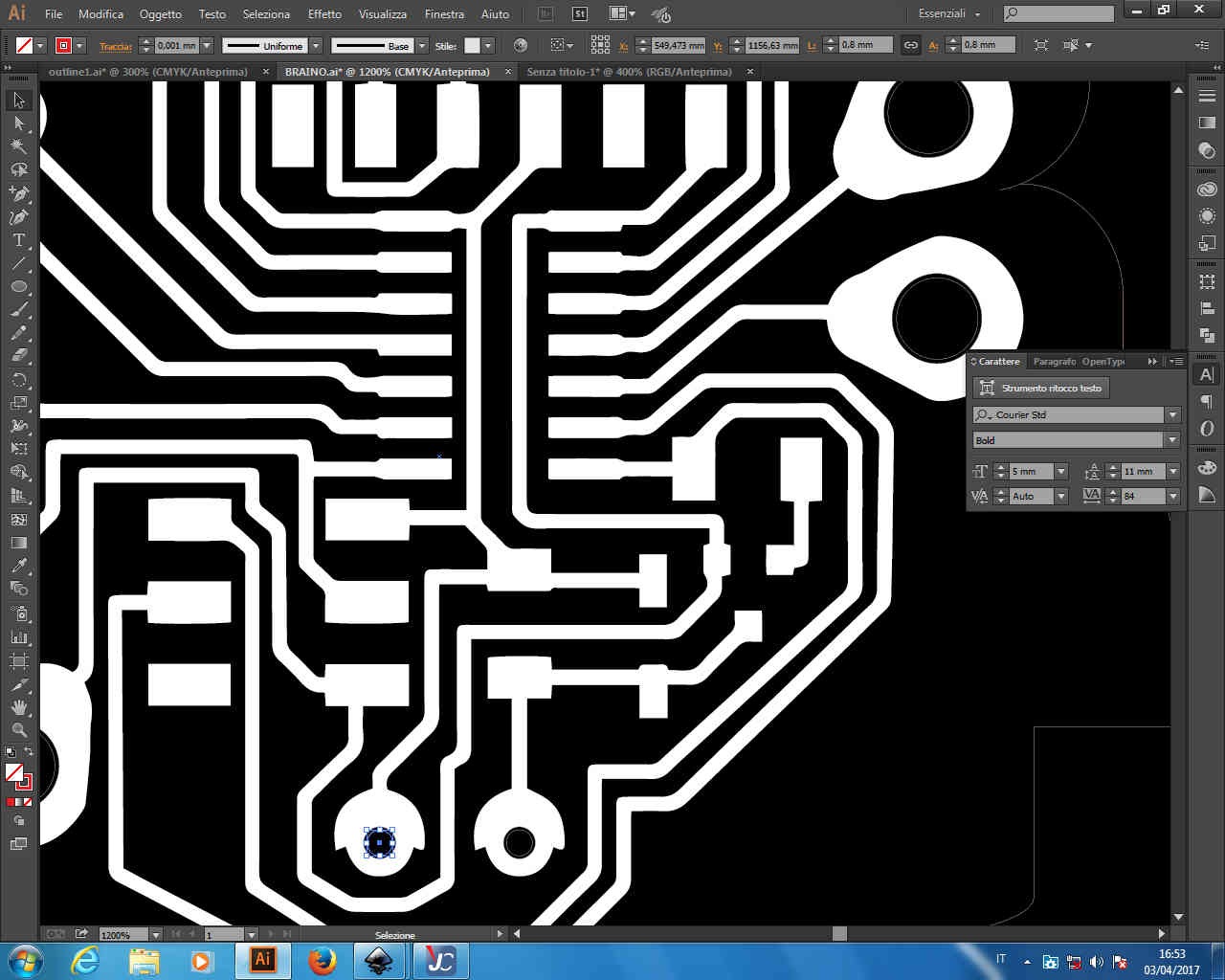
I used Illustrator instead of GIMP because free drawing is not the strong arm of my abilities:
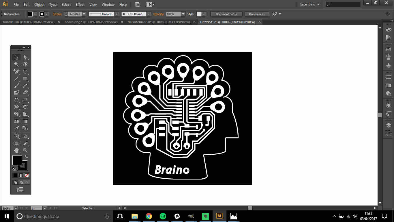
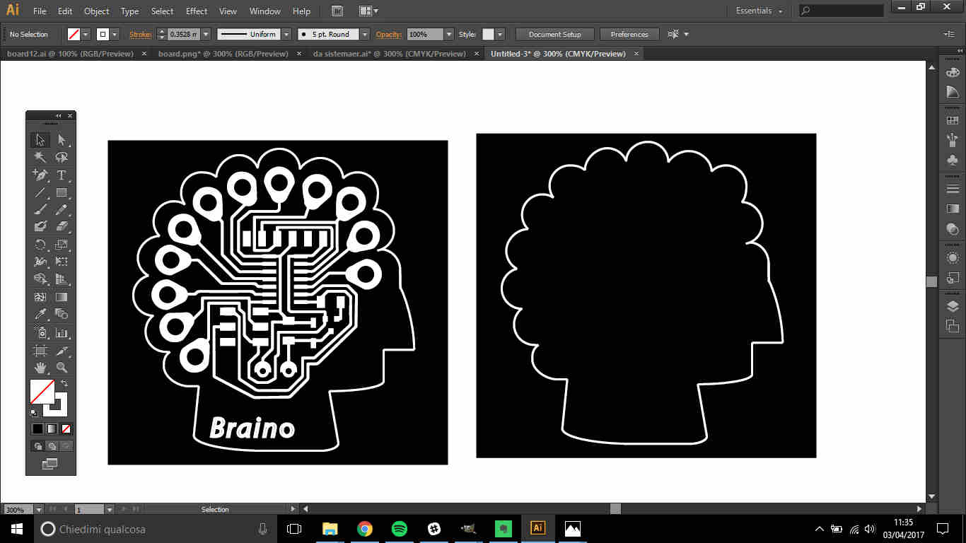
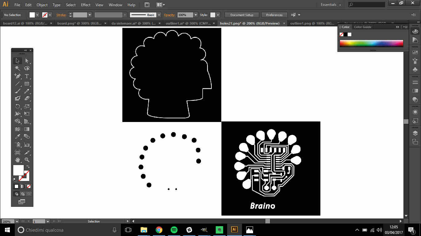
 I copied and pasted the whole sketch in three different files so as to take out from them 3 images:
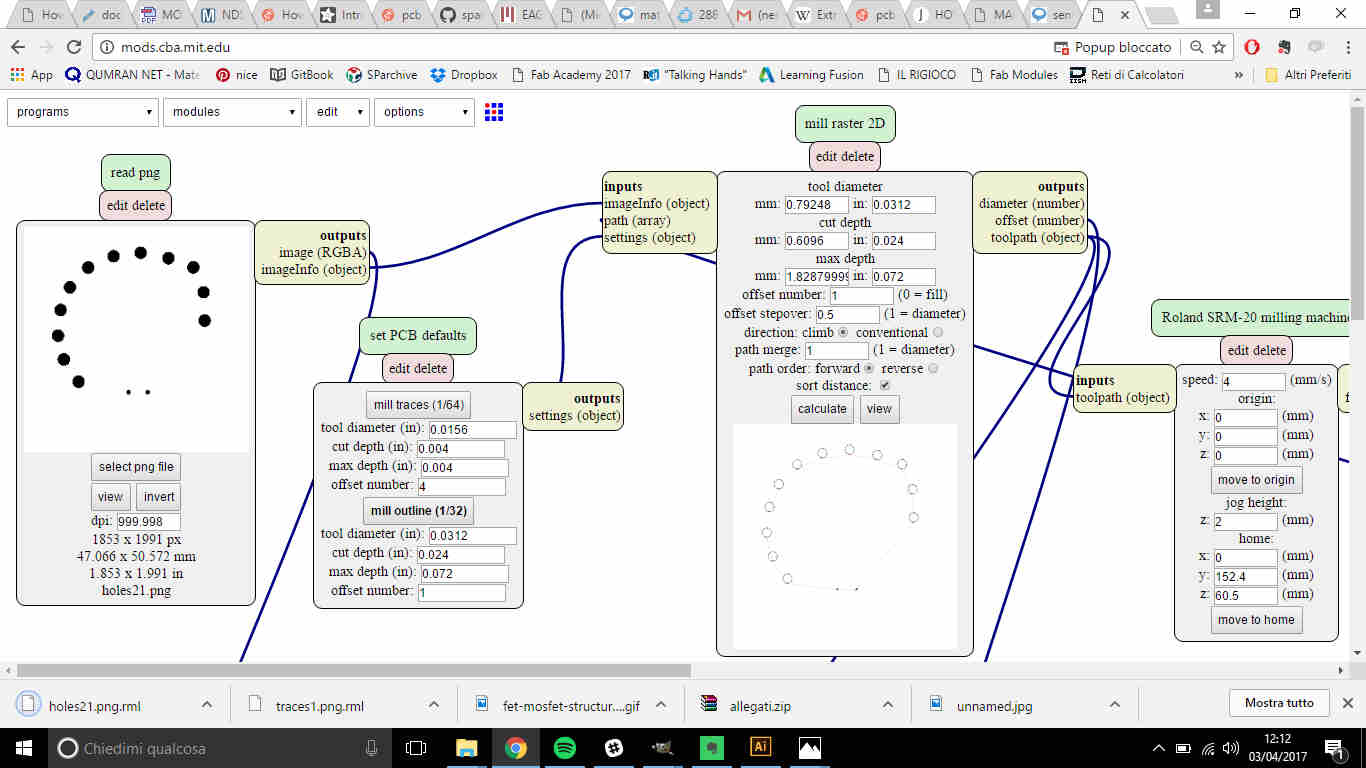
- traces: where I had the traces, text and pads with no hole - to be engraved with 1/64 of inch mill;
- holes: where I just had the holes I had to cut (black infill) - to be cut with 1/32 of inch mill;
- outline:where I just had the outer profile.
 I then exported them as .png files and send them to fab modules
(see week4
for detailed settings).
I then exported them as .png files and send them to fab modules
(see week4
for detailed settings).
 Once I loaded outline file I saw the path of the mill would have been the following:
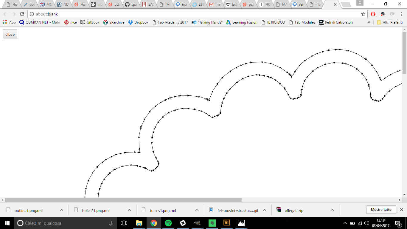 NB: notice that what is in black would be cut out and what in white is left. In my case
anyway it didn't make much difference because the inner path was still out of traces range.
NB: notice that what is in black would be cut out and what in white is left. In my case
anyway it didn't make much difference because the inner path was still out of traces range.
Now, I know it's rarely machine's fault if you fail, but I believe there was also an ill omen running against me:
First attempt: the PCB board didn't stick enough to the plate and it moved while milling...what came out
was to be thrown away but fortunately I didn't break the mill.
Second attempt: I forgot to pull up the mill before moving and I broke it.
Third attempt: I changed the broken mill with a defective one and it didn't cut anymore after a while.
 My mind went like...
Looking up at that demon that was mocking at me, I saw the lasercutter and I decided she could be my saviour.
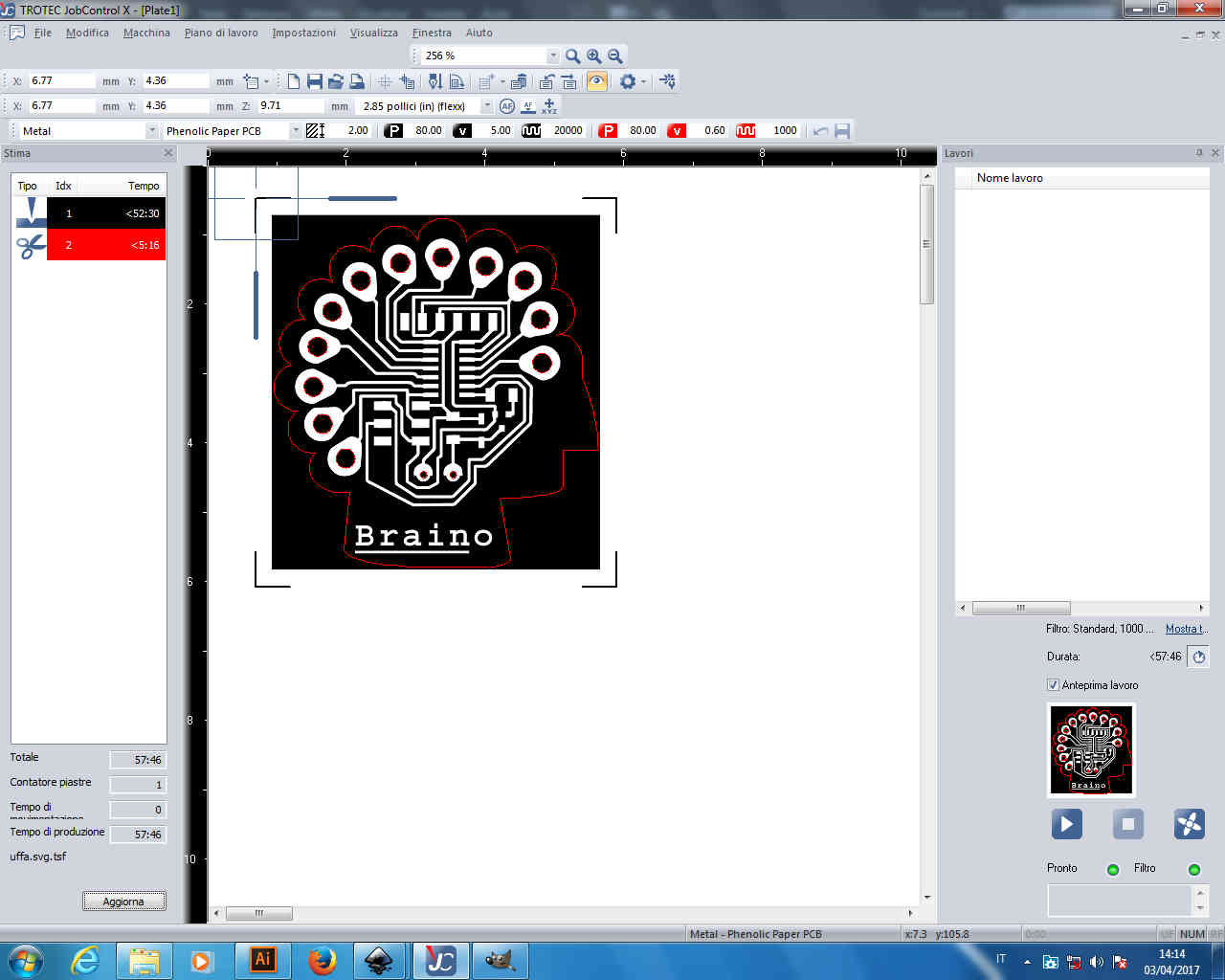
I so edited my exportation from .png ( now preparing files for milling looked so much easier! ) and I made it vectorial
(see week2
for how to vectorize an image on Illustrator) paying attention that everything that had to be engraved was
in black, cuts in red and what to be left in white:
.jpg) ( That thin line is 0.001mm thick in red and there are also red circles inside pads)
( That thin line is 0.001mm thick in red and there are also red circles inside pads)
I so repeated
printing procedure from Illustrator and set parameters on JobControl
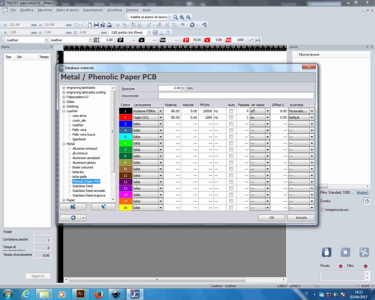 Thanks to
Luca Giacolini for parameters setting.
Thanks to
Luca Giacolini for parameters setting.
Anyway, first result hadn't holes cut properly
and so I sacrificed that board to find right cutting setting
 From 80 W power and 0.6 speed I moved to 100 W power and 0.3 speed for cutting but still I had bad results because
holes didn't detach and I damaged pads in pushing them out.
From 80 W power and 0.6 speed I moved to 100 W power and 0.3 speed for cutting but still I had bad results because
holes didn't detach and I damaged pads in pushing them out.
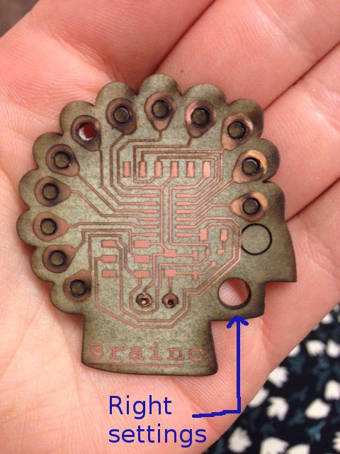
 Since the outline had been cut finely, holes problem's could come from the fact that the cutting line was precisely
the hole border and so there was copper that hadn't been scrabbled away that may prevent the laser from passing the
whole material thickness. Consequently, I shrunk circles so as they didn't touch copper layer.
Since the outline had been cut finely, holes problem's could come from the fact that the cutting line was precisely
the hole border and so there was copper that hadn't been scrabbled away that may prevent the laser from passing the
whole material thickness. Consequently, I shrunk circles so as they didn't touch copper layer.
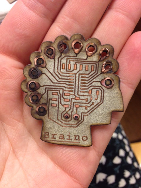
 And.......
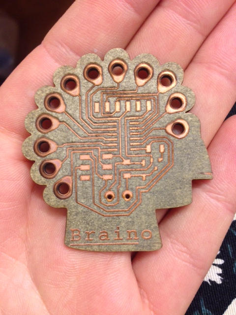 Tadaaaaaaaaaaaaaaaaaaaaaaaaaaaaaaaaaaaaaaaaaan!
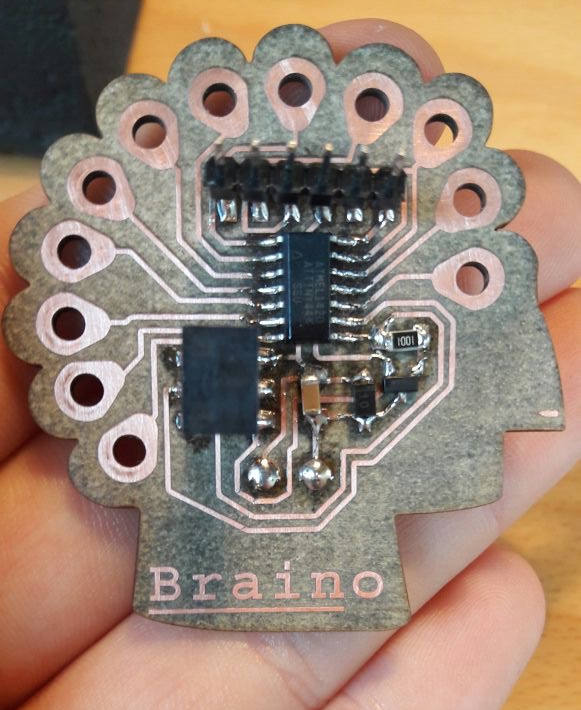
My Braino came out well!!!
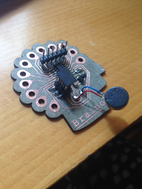
Braino Soldering
For soldering tips see week 4.
I wrote my BOM
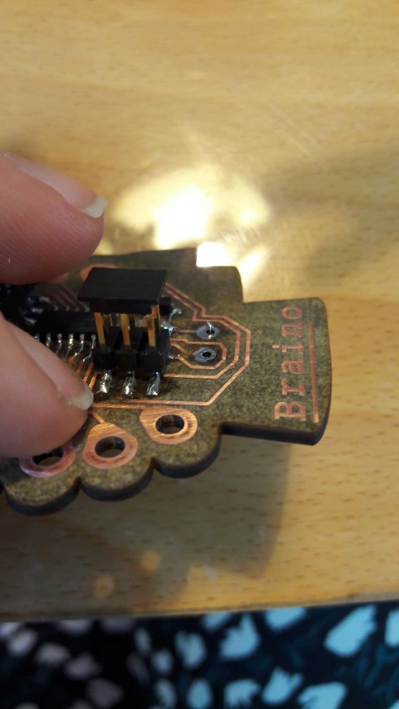
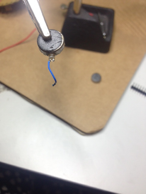
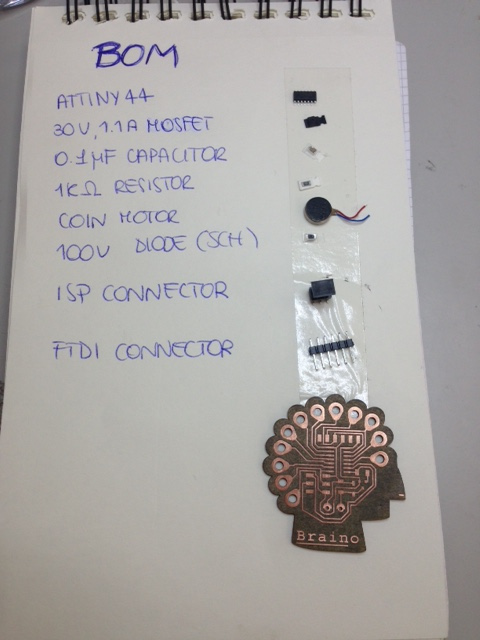 I soldered some components and then I flayed coin motor wires:
 NB:to know the direction of the diode, check the side that has one or two lines
(they sign the line of diode symbol: -->| ); notice that in my circuit, diode is mount the other way up because it has to prevent
current from passing.
NB:to know the direction of the diode, check the side that has one or two lines
(they sign the line of diode symbol: -->| ); notice that in my circuit, diode is mount the other way up because it has to prevent
current from passing.
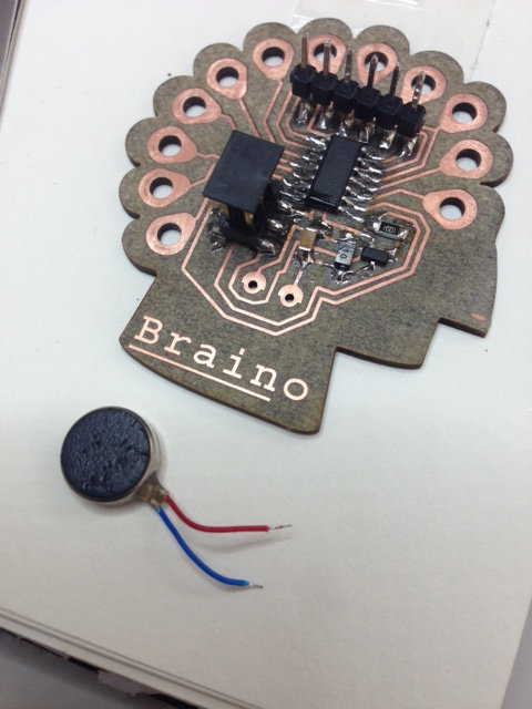
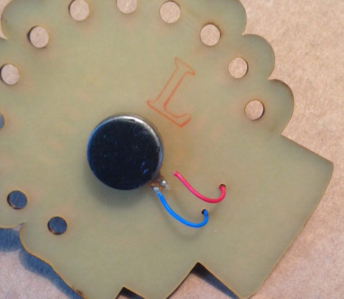
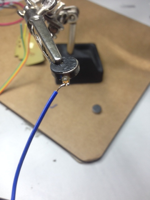
 Then I soldered the motor:
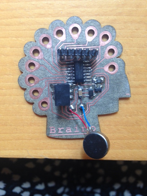 Since one of the wires broke, I decided to use pads properly ( ;) ) and I re-arranged my board:
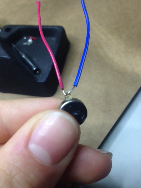
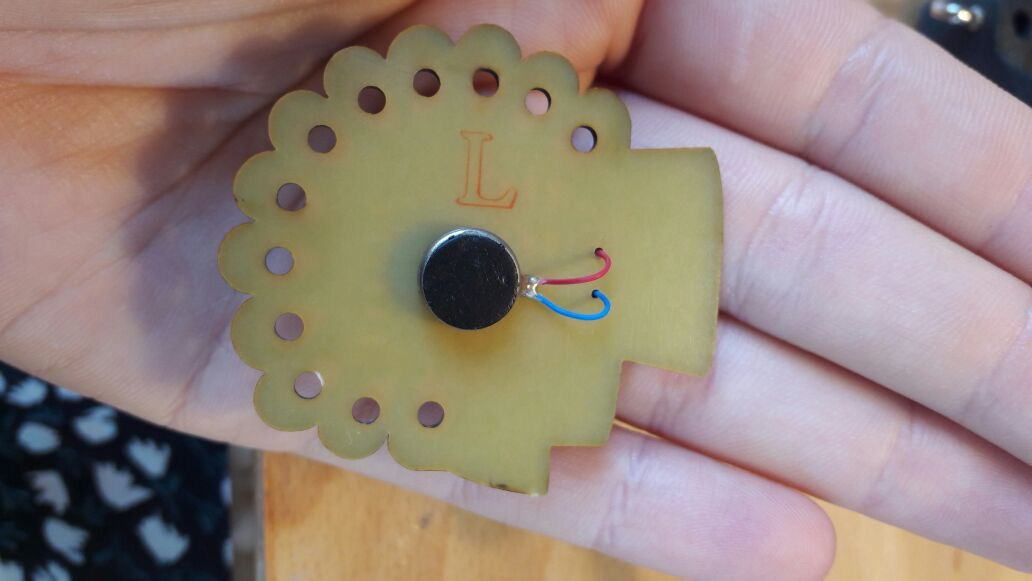 NB: so as not to get confuse with blue and red of motor wires, I looked up at this
datasheet to check which was + and which was - .
NB: so as not to get confuse with blue and red of motor wires, I looked up at this
datasheet to check which was + and which was - .
After soldering, I checked my circuit with multimeter and it seemed to be work fine.
Experiments
Grove shield
I couldn't help testing it immediately, still I was afraid to damage it somehow. Therefore, I first tested another Grove vibration module
I had with an Arduino Uno usig the code I found here:
int MoPin = 9;    // vibrator Grove connected to digital pin 9


        void setup()  {

          pinMode( MoPin, OUTPUT );

        }


        void loop()  {


          digitalWrite(MoPin, HIGH);

          delay(1000);


          digitalWrite(MoPin, LOW);

            delay(1000);

          }


        }
NB: check which pin you are linking the module to ( since I had a previous version
of Grove shield I hadn't pin 9, I linked to D7 pin and changed it in the code ).
everything went ok just by copying and pasting
the code on Arduino IDE.
Arduino Uno, Grove shield and vibration motor module from Silvia Palazzi on Vimeo.
Braino testing
I then wanted to move on to Braino board and make it working, but as soon as I connected it to the ISP programmer and to my notebook's USB port (I didn't even send a code to it), it
started vibrating at full pelt so fast that a wire broke:
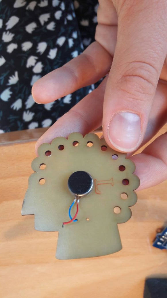
 Unfortunately it broke at motor junction and not where I soldered it, so I tried to fix the motor like a really surgeon:
 I heavily glued it and solder it back to my board, but when I connected as before, nothing moved, which was quite strange cause I didn't change
traces or components but just fixed the motor.
I heavily glued it and solder it back to my board, but when I connected as before, nothing moved, which was quite strange cause I didn't change
traces or components but just fixed the motor.
Before despairing, I wanted to load a code on it.
Loading the BOOTLOADER onto the ATtiny44
Despite preferring C code to Arduino language (let's say it, it's far better going to the core of pin value setting instead of learning libraries' functions),
I know Arduino IDE could be a nice friend for my final project programming and I therefore wanted to make acquaintaince with it.
I wanted to load the bootloader onto the ATtiny44 so as to be allowed to send Arduino code to my board directly. To do that I found a nice
tutorial but, going through few lines I realized I had an older version of Arduino software and I got the 1.8.2 one here.
I then simply followed the instruction listed to add ATtiny44 among the supported boards and went through Tools--> Burn Bootloader.
I received an error message that said to check connections. I opened my eagle board file and I saw I forgot to connect ISP RST pin to PB3 of the ATtiny44.
I took up a flying solution:
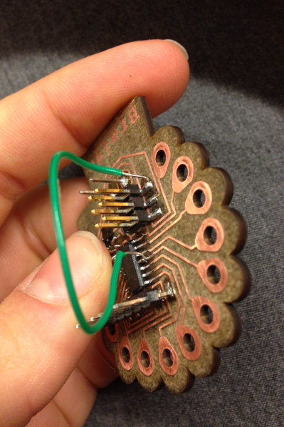 I tried back later and I successfully loaded the bootoader.
Quite a tricky debugging afternoon
I then tried to load the previous code, making proper changes to pin number. To do that I checked ATtiny44 Arduino pinout:
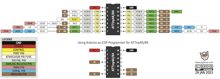 I linked the motor to PA5 pin that, according to previous image corresponded to pin 5 of Arduino.
I so used the following code:
int MoPin = 5;    // vibrator motor connected to digital pin 5


      void setup()  {

        pinMode( MoPin, OUTPUT );

      }


      void loop()  {


        digitalWrite(MoPin, HIGH);

        delay(1000);


        digitalWrite(MoPin, LOW);

          delay(1000);

        }


      }
Nothing worked.
NB:
I thought the problem could come from digitalWrite. I then came to the point that makes me say I don't like Arduino that much, because you don't know
exactly what you're doing. I then looked online for explanations about this function:
I imagined it not to be so suitable for PWM pins because it simply set a pin HIGH (max output voltage) or LOW (0V).
The function I was now looking for was analogWrite that fulfils PWM requests better, since
it controls varying signals and not just HIGH or LOW. The fields it requires are: analogWrite(pin,value).
I retried with this code:
int MoPin = 5;    // vibrator motor connected to digital pin 5


        void setup()  {

          pinMode( MoPin, OUTPUT );

        }


        void loop()  {


          analogWrite(MoPin, 255);

          delay(1000);


          analogWrite(MoPin, 20);

            delay(1000);

          }


        }
Nothing worked still.
May it depend on pin number? Maybe I misinterpreted ATtiny44 pinout and I had to set pin number as 8.
I then tried:
int MoPin = 8;    // vibrator motor connected to digital pin 5


      void setup()  {

        pinMode( MoPin, OUTPUT );

      }


      void loop()  {


        analogWrite(MoPin, 255);

        delay(1000);


        analogWrite(MoPin, 20);

          delay(1000);

        }


      }
No result.
Noe the only remaining possibility was that my motor didn't work weel after re-soldering it.
I therefire desoldered it and tried to feed it with 0.1 A and 4.9 V with the regulated power supply but nothing moved.
I evidently broke it.
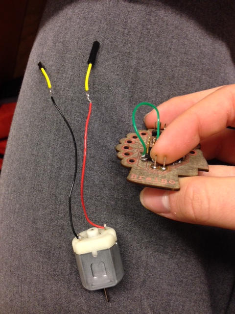
Having no other vibration motor to use, I soldered two male pins into motor pads and moved to another DC motor to whose wires I soldered two female pins:
 I then reload last code but I received back an input/output error message and I was close to be driven mad but I tried to calm down
looking a bit on the internet about topics related to my work.
I then reload last code but I received back an input/output error message and I was close to be driven mad but I tried to calm down
looking a bit on the internet about topics related to my work.
While doing this, I tried to scroll back all the process I followed till the very beginning and
I remembered I started from an example that used a BJT instead of a MOSFET, but I simply replaced the first component with the second without caring that much
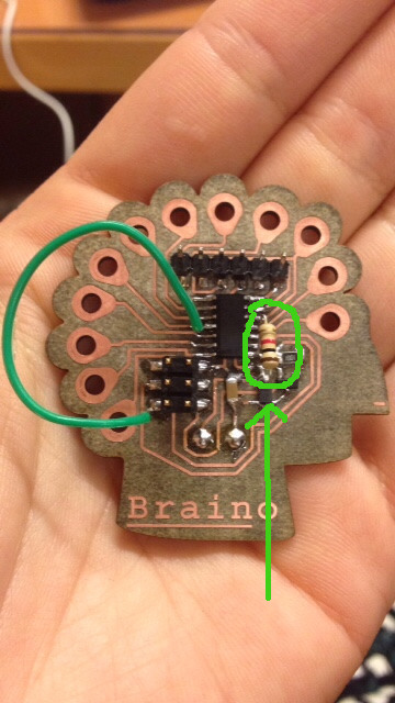
if I could do that. Looking for more info about MOSFETs I found this image:
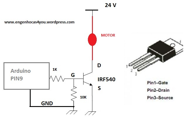 It nearly represented part of my circuit but, thanks to Pietro suggestion,
I noticed something I was missing in my board:
It nearly represented part of my circuit but, thanks to Pietro suggestion,
I noticed something I was missing in my board:
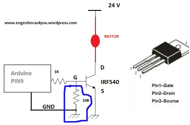 That resistor is a really important one, since it is pull-up one and it is needed to grant pin input levels are logically low when output devices are not
connected (that's why my vibration motor ran so fast as soon as I connected to power ;) ).
That resistor is a really important one, since it is pull-up one and it is needed to grant pin input levels are logically low when output devices are not
connected (that's why my vibration motor ran so fast as soon as I connected to power ;) ).
Therefore I needed another flying solution:
 Running the code gve me back no result again, but my instructor told me that p-mosfet are quite more complicated to be used (I admit I cared too little about p and n
type differences, believing it just regarded internal system of current amplification). According to his suggestion I replaced the
p-mosfet with an n one.
Running the code gve me back no result again, but my instructor told me that p-mosfet are quite more complicated to be used (I admit I cared too little about p and n
type differences, believing it just regarded internal system of current amplification). According to his suggestion I replaced the
p-mosfet with an n one.
Setting pin 8 gave again no result but using ATtiny44 Arduino pinout as I did the first time ( so setting pin 5 for PA5 ) ended up like this:
Braino & vibration motor from Silvia Palazzi on Vimeo.
Finally it worked :)))
NBI set pin 2 seconds high and 10 seconds low
C code
I moved back to more familiar and appreciated fields: C lannguage :)
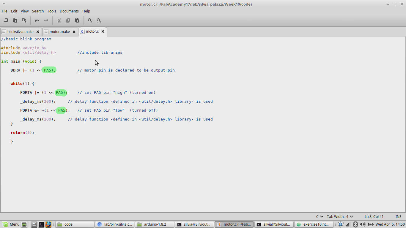
To make the motor work, I simply edited embedded programming's
LED blink code
replacing PA5 pin where needed and I used relative makefile changing s project name.
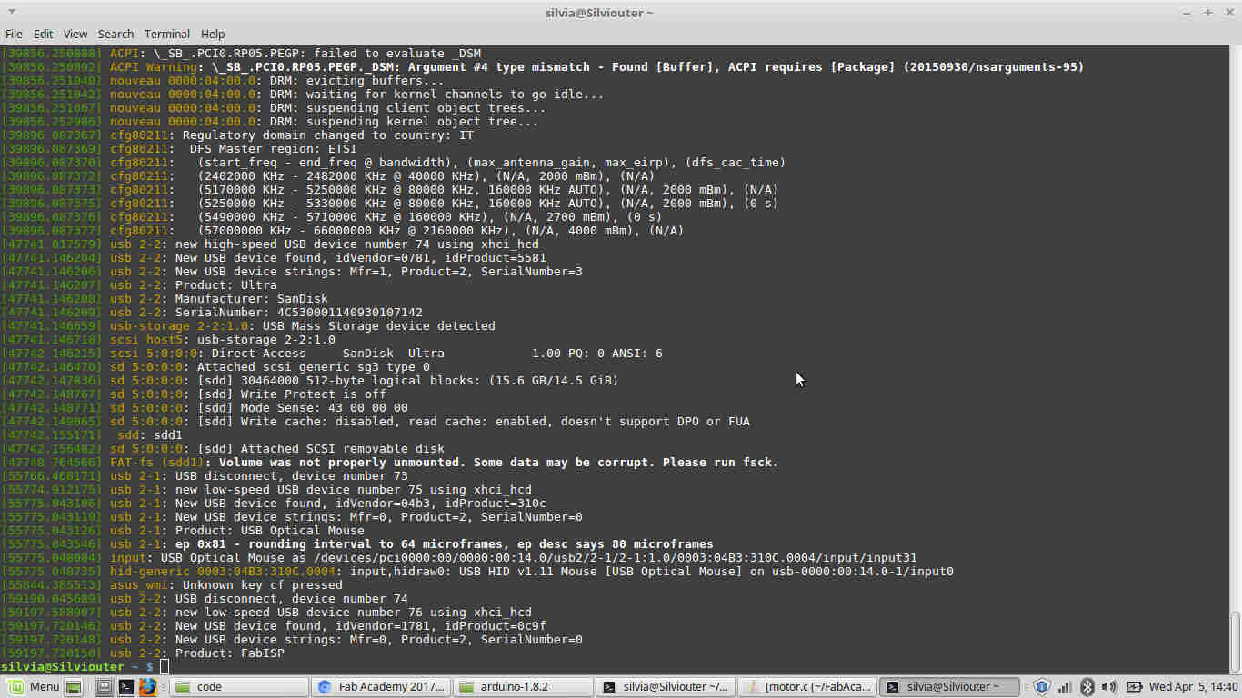
 I connected the board to the ISP and to computer ad checked this one saw them:
 I moved to the directory of the code:
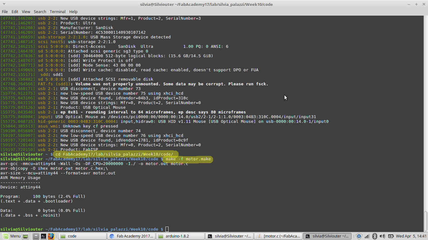 I then ran
 make -f projectname.make
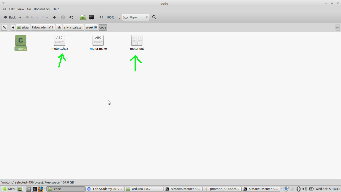
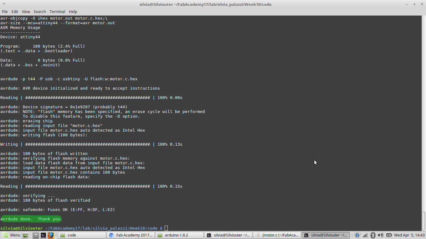 And I checked an .hex and .out file were created:
 I then ran
 make -f projectname.make program-usbtiny and....
Conclusions
This week assignement was really challenging and entertained me a lot. I rarely decide to follow a different path
from the easiest one when it's about something I'm not handy with, but this time I decided to start from the really-low-one level
to deeply understand what-I-had-to-put-where. I may have payed more attention to all differences among components but, having so little knowledge
about electronics, sometimes I didn't even imagined using a component rather than another could have made such difference.
I'm quite happy of the result, at least for my board (whose schematic must be changed a bit) and also for having had the opportunity to even just solder coin motors.
I ordered them and I hope they'll arrive soon so as to start my final project prototypes.
About Arduino, I may say I still prefer C language for programming but I
recognise Arduino IDE to be slimmer for heavy and long codes.
I would have liked to test also stepper motors, but I'll have next week to go along with them for machine design.