Third week assignment was to get in touch with
computer aided cutting, both individually and group co-working.
What we basically had to do was to:
- cut something with the vinylcutter
- test laser cutter parameters (in group)
- design and make a parametric press-fit kit
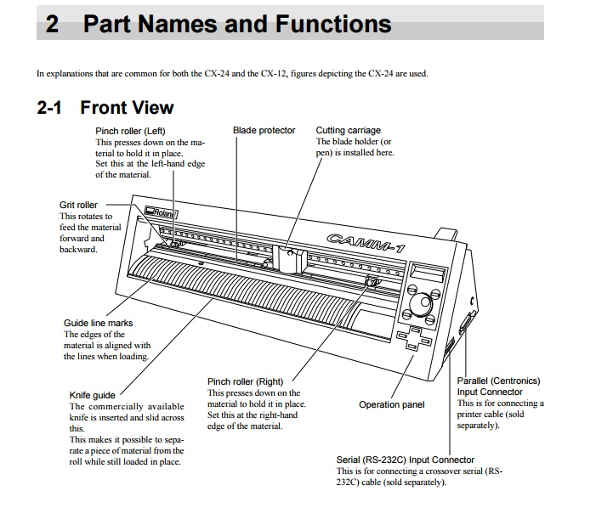
Vinyl cutting:Roland CAMM-1 GX-24
.jpg)
I had never used our lab plotter before this week and I therefore had a look in the web:
TI realized there are principally three ways of cutting vinyl with the plotter:
- import a .png in Roland's software, Cut Studio (you can download setup and drivers here);
- use fab modules to edit your .png/.svg file, save it and send it to the plotter with shell commands;
- use fab modules to directly send the file to the machine.
Once you have your piece of vinyl cut, you then have to use transfer for sticker positioning.
Cut Studio: let's start easily
After getting my OS drivers and installing the software,
(maybe a little old but nice tutorial
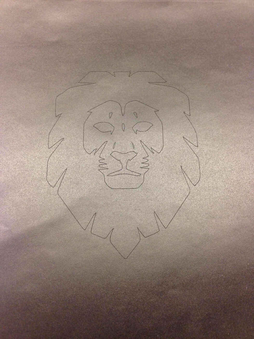
here ) I searched on the internet for a logo I would have liked to stick to my notebook and I found this:
![]()
I then vectorized (following the steps I describe here) and saved it as .svg.
Was it necessary?NO.
I opened Cut Studio and tried to go through File-->Import and choose my .svg file but an error messaged
warned me the format of the file I wanted to use was incorrect.
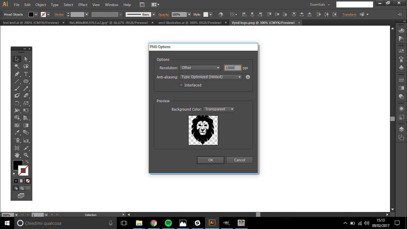
So I just opened my .svg file on Illustrator and exported it as .png file (File-->Export PNG file).
IMPORTANT! To have the least pixeled effect you have to export at 1000 dpi/ppi.
NB:In using Roland software, you don't need to define width and height of the image previously, you can do it directly on the artboard.
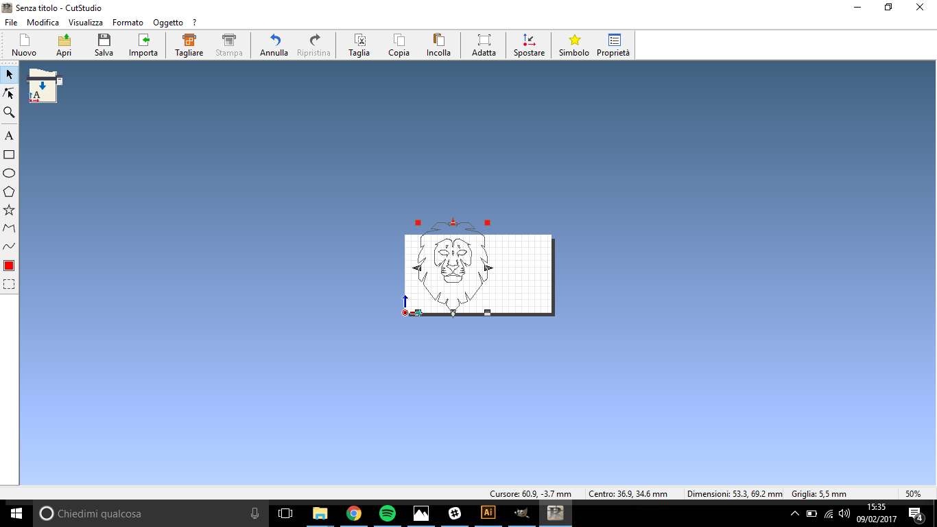
Once I imported, positioned and resized my lion, I right clicked with mouse on it and selected Image Outline-->
Extraxt Contour Lines.

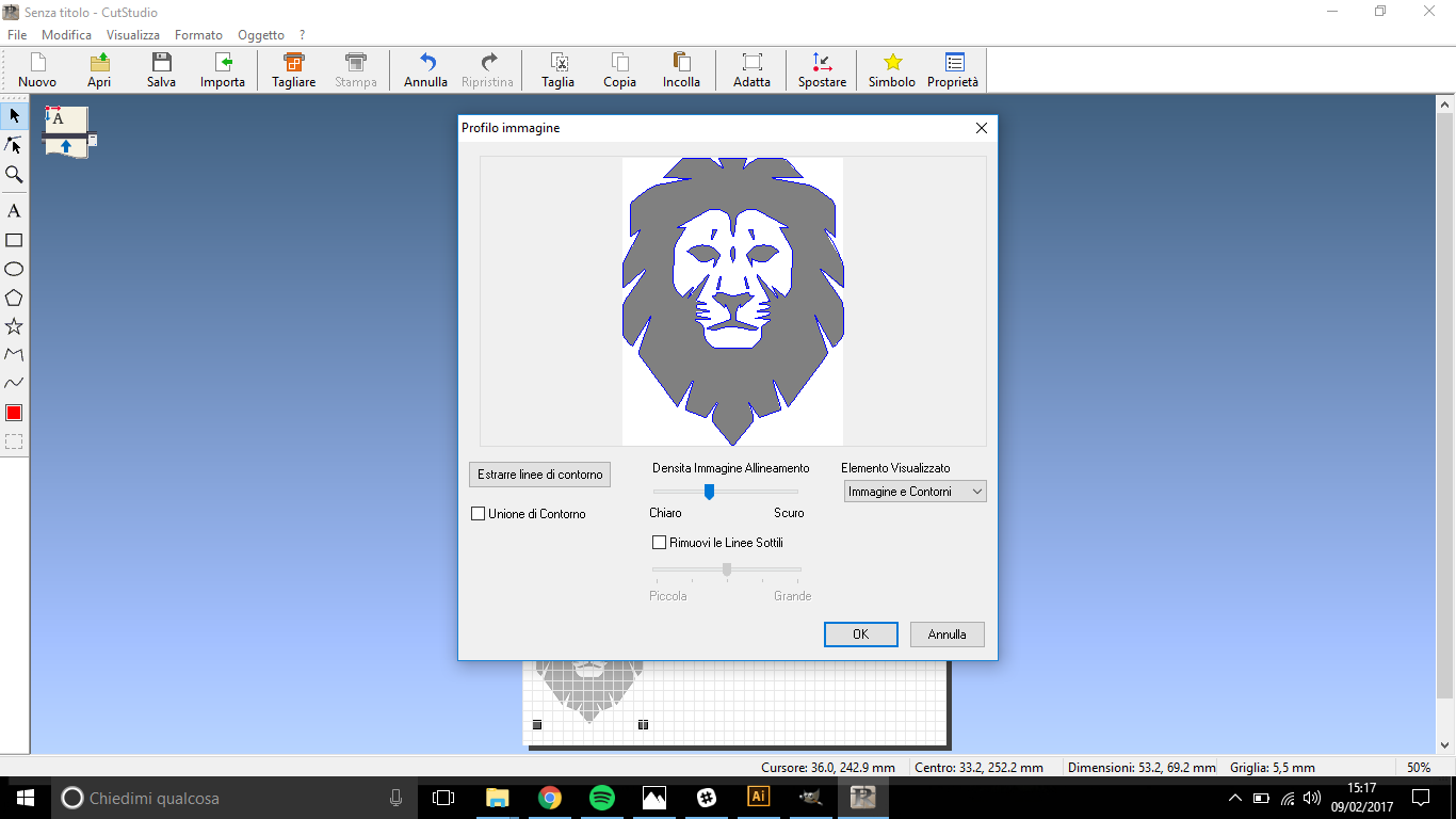
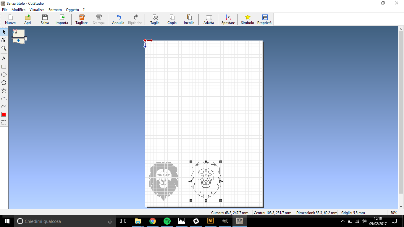
Then, a new mono-color image appeared on my original one, which I deleted.
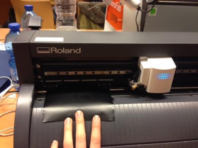
Meanwhile, I loaded the vinyl on the plotter to let it scan the dimension of the piece I was using. To do so I:
- pushed the lever forward
- loaded the sheet under the two wheels (NB vinyl piece has to be at least as large as wheels distance)
- pulled the lever backward
- as the display asked SELECT SHEET I pressed down button until I found PIECE voice
- pressed down button until the voice "PIECE" appeared
Then blade body moved from extreme right along the rail till the extreme
left and moved up and down, right and left on the sheet to check its dimensions.
NB:you have to do this operation everytime you want
to cut the vynil: if you are using the software, doing this before resizing
the image helps you get the real dimension of artboard and scale you work properly.
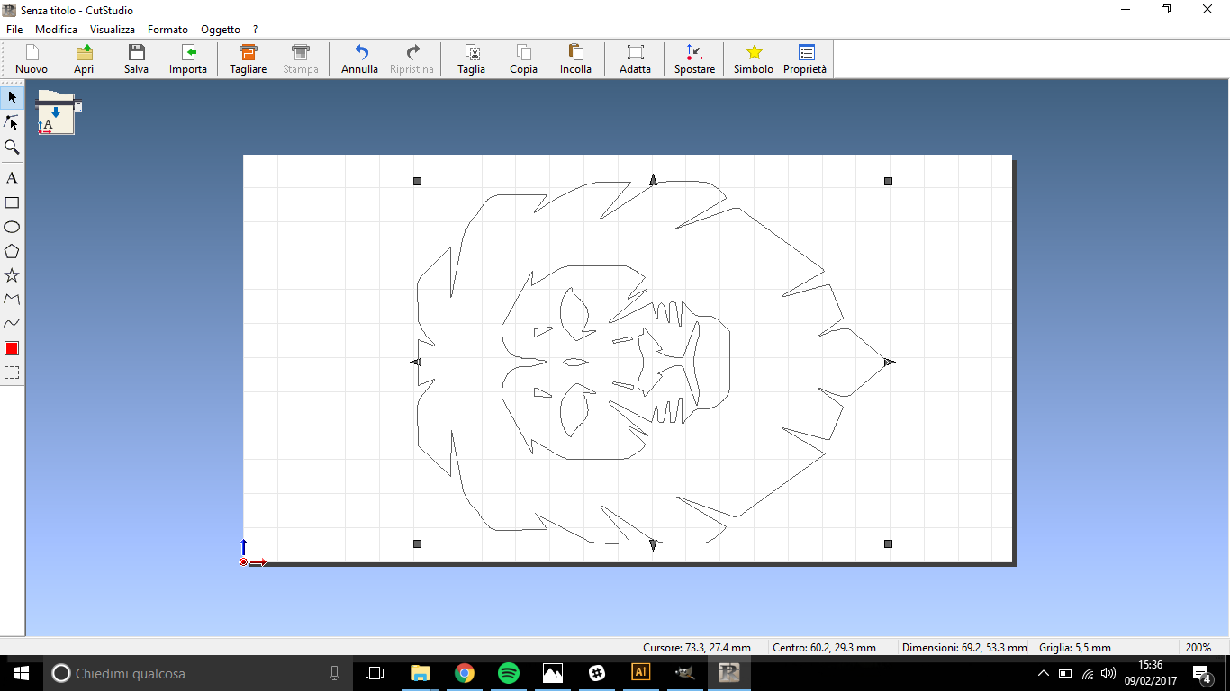
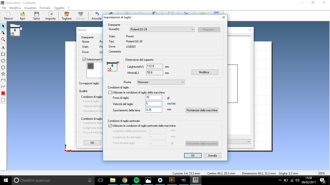
To tell Cut Studio to scan real vinyl dimensions go through File-->Cutting setup: a window will let you choose your plotter name (plotter has to be USB connected to do this) and below you'll find:
- Size: width and length of the working area and you can edit them by clicking on “Get From Machine”, that automatically shift dimensions with the ones scanned;
- Rotate: orientation can be changed if needed;
- Settings: specific cutting speeds can be set here or you can use “Machine Setting” which are set on the cutter
NB: In older versions you have to click on File-->Properties
When each setting is done, open Cutting on toolbar and have a look at the window that will open:
- thick Select Cutting Color and click on the color below;
- check speed and force are the one you set
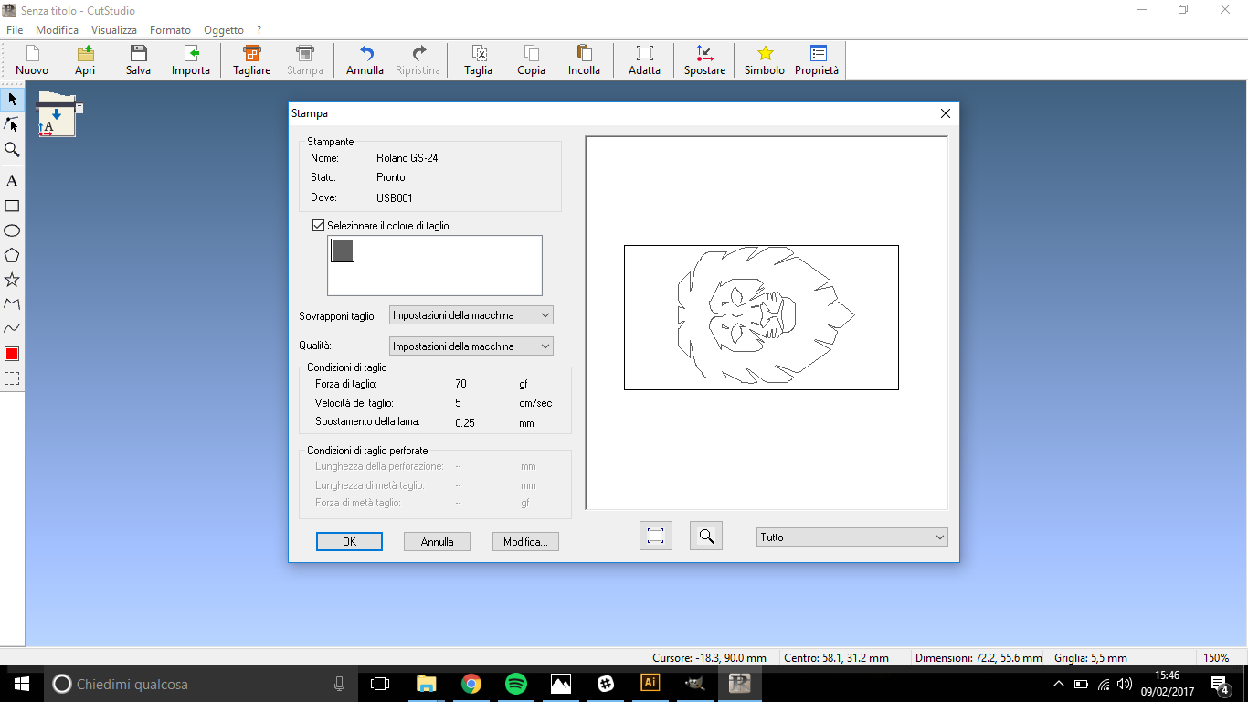
Setting done, run the cutter pressing OK.
As the blade stops, push the lever forward and extract vinyl piece:
if you're able to take away easily those parts that surround your image,
it means the force/speed relationship was ok, otherwise force was too low/
speed too high; if also the white rear layer has been cut, force was too high/speed too low.
ADVICE:It's best to do some test with a little square to find
right force and speed relationship before running your work .
Fab Modules: older version
My instructor asked me to cut him a sticker, so he sent me a .camm file
via email and what then I had to do was to sent it to the plotter with shell commands.
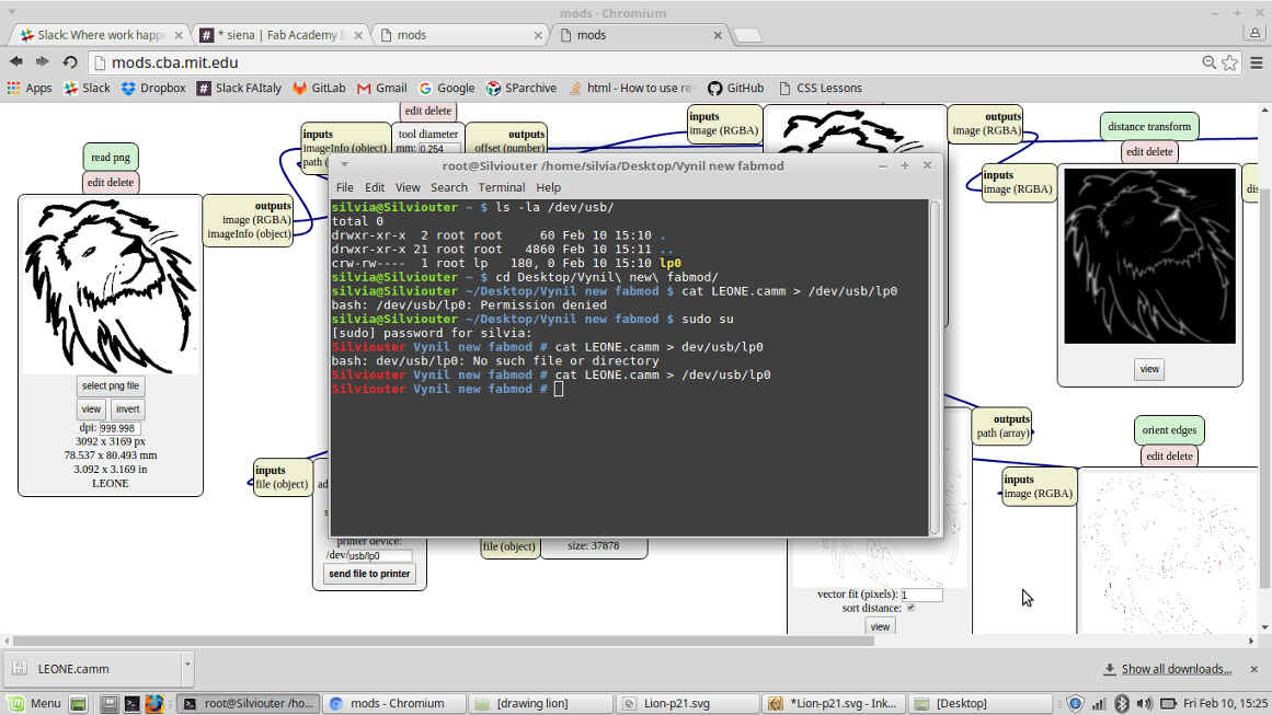
I followed these steps:
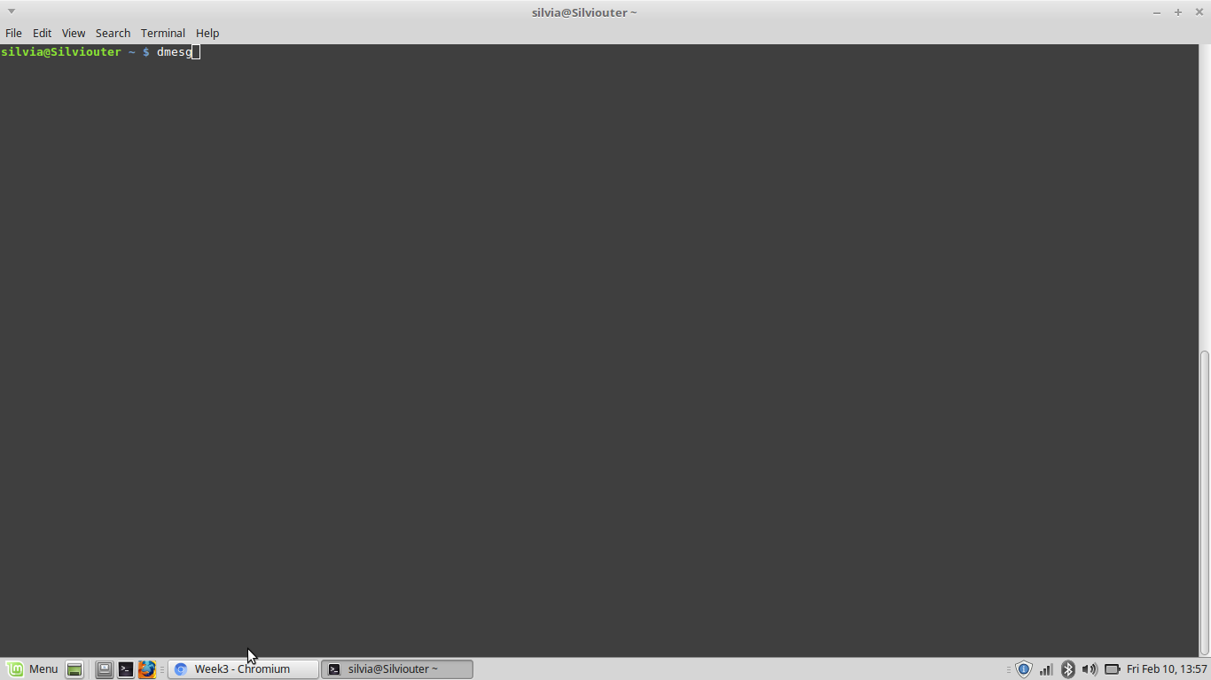
dmesg
to see the path of Roland CAMM on my pc
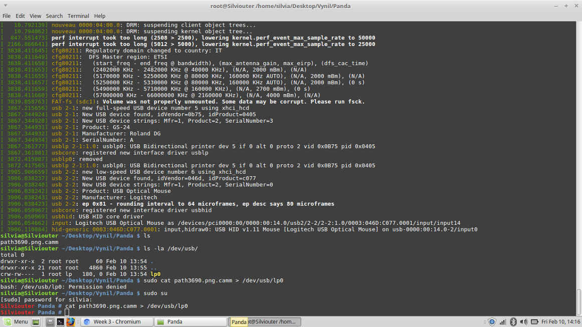
ls - la /dev/usb
in the result of this message you have to look for "lp#"-#is a number- cause you'll need it later
cd path/to/file/directory
*to check if the file I wanted to cut was inside
ls
sudo cat filename.camm > /dev/usb/lp#
If a "Permission denied" message appears-it does with Linux Mint- add these two messages:
sudo su *user password is needed; you become super-super user- there's no action you aren't allowed to do
cat filename.camm > /dev/usb/lp#
Then the plotter started cutting.
IMPORTANT! Never forget "/" before "dev"! It is necessary to go back to main (the really main one, not home) directory and enter devices.
After I took away the vinyl piece, I found out the upper part of the image hadn't been cut:
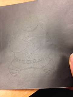 Since I didn't know if it depended on me or on a file error, I chose a new image to use
in fabmodules and I discovered it was my instructor mistake (muahahaah).
Since I didn't know if it depended on me or on a file error, I chose a new image to use
in fabmodules and I discovered it was my instructor mistake (muahahaah).
WhenI opened the link above and I saw just and empty page with
"fabmodules
input format"
on the upper left.
I pressed on the grey rectangle and chose ".png", my file appeared and
on the right of the page I could read its dimensions, dpi... but it wasn't possible to change them.
NB: in using fabmodules you should set your image size before loading it.
Meanwhile a new grey field appeared on the right, I clicked on it to set the output format.
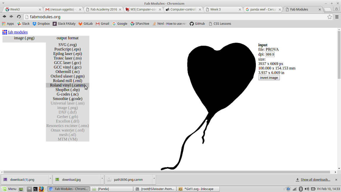
Under image description a new caption ("option") let me set force and speed
of the blade and also origin position.
Then in the third rectangle you have to set "process" and I chose "cut vinyl":
specific info about the plotter came out in "process" paragraph.
I then changed force and speed and pressed "calculate" to get cutting path.
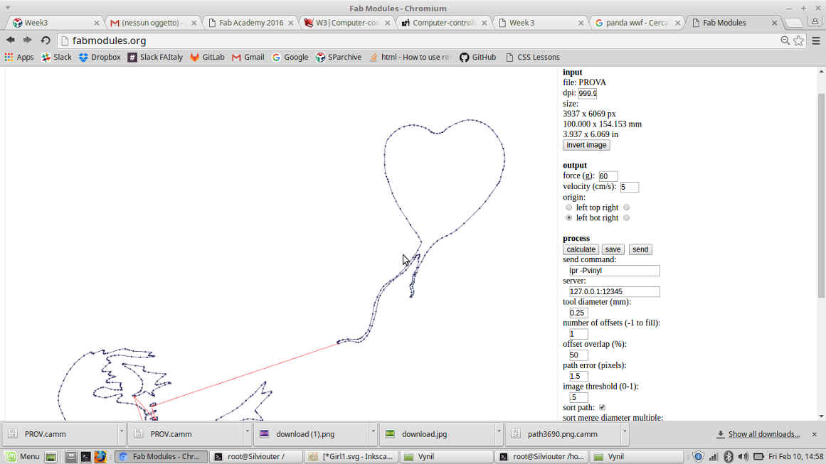
I couldn't make the machine run by pressing "send" so I saved .camm file and repeated steps written above in the shell.
Here I show the result:

New Fab Modules
Last way I wanted to exploit in vinyl cutting was to use
new fab modules.
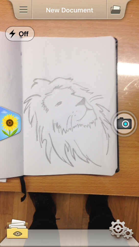
I wanted to go through the process of drawing->vectorizing->vinyl sticker
to see the quality of the result I could obtain. So, first of all I made a drawing:
.jpg)
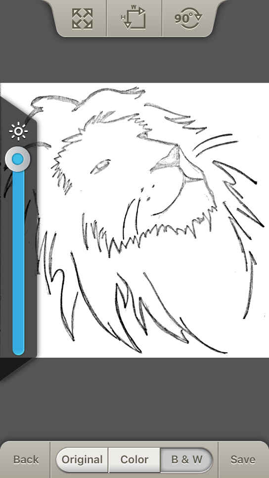
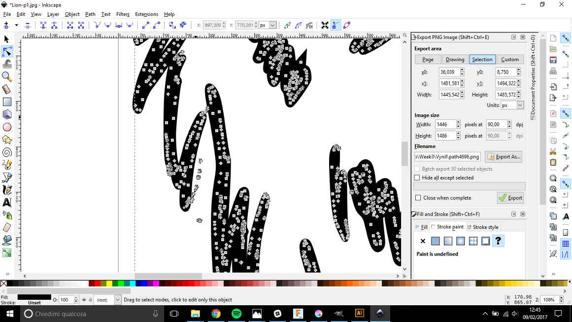
Due to the fact that vectorizing the drawing picture on Inkscape directly from a photo presented weak boundaries, I used DocScan app on my Iphone to get a quite defined-in-lines image.
.jpg)
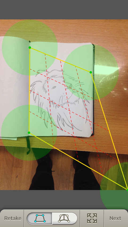
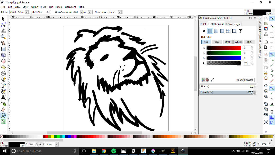
Then I vectorized it on Inkscape following the step explained here
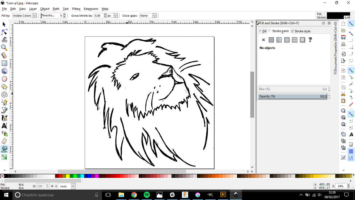
Before exporting it as a .png, I used "Fill bounded areas" tool (in the left vertical bar) to increase line thickness of my drawing and "Edit path by nodes" to delete imperfections and grouped all paths.
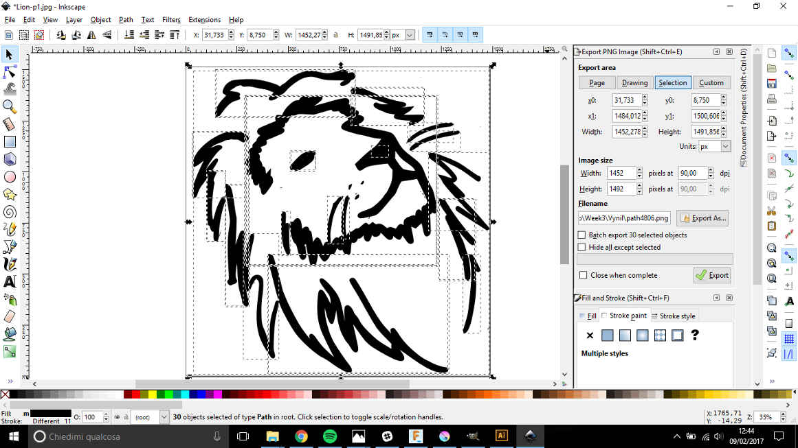
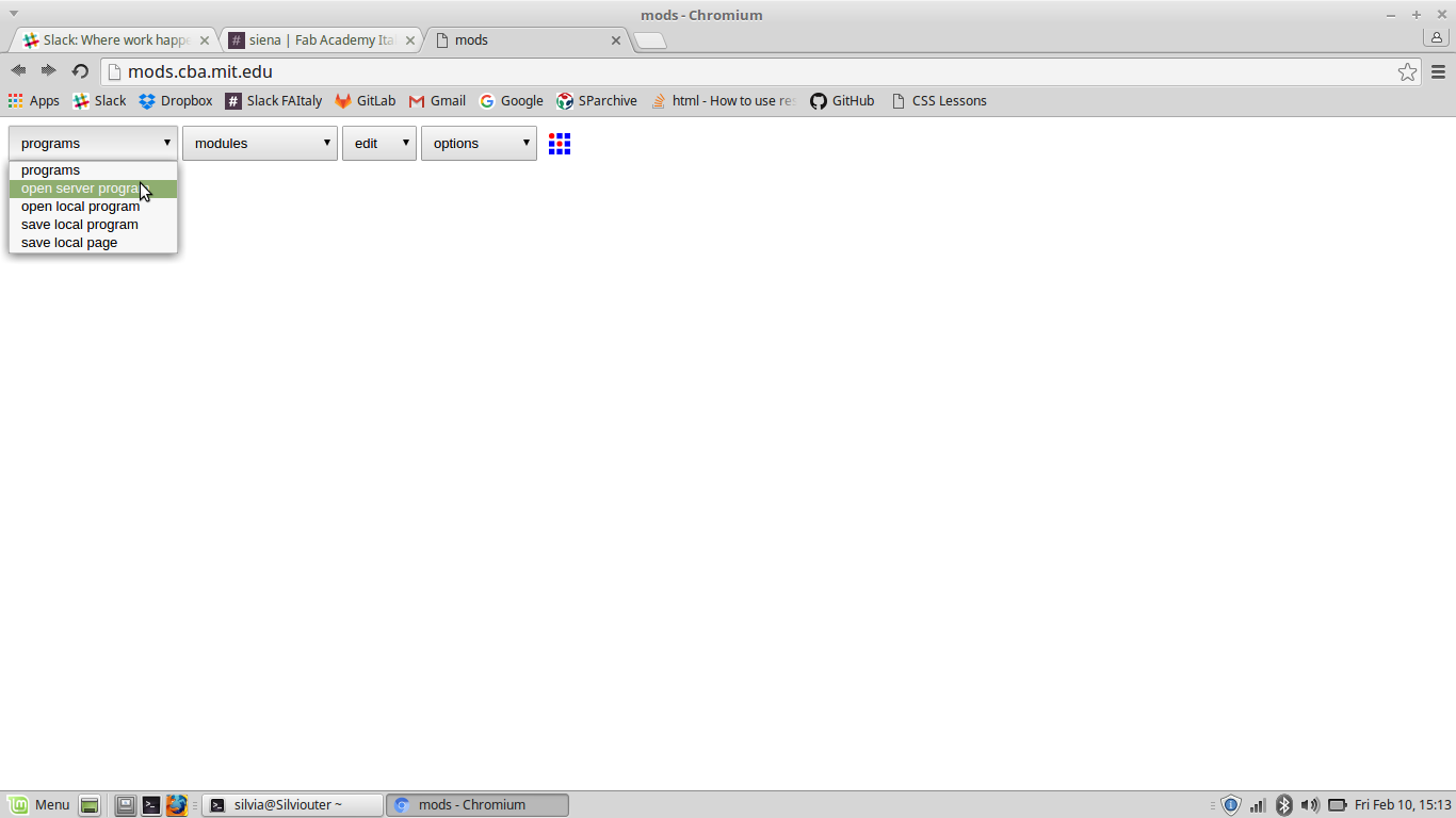
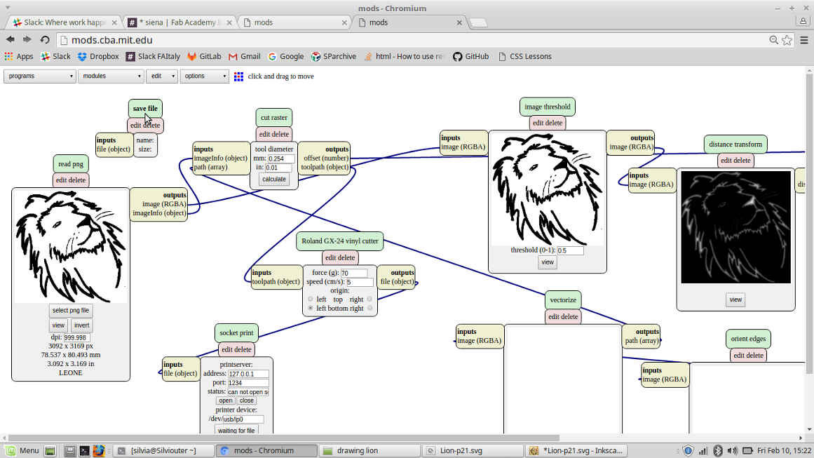
After that, I opened new fab modules and on the upper left of the page I could read 4 fields:
- programs
- modules
- edit
- options
I chose "open server program" in the first field.
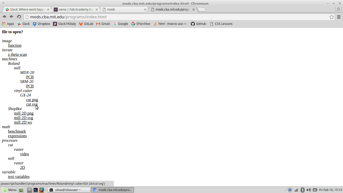
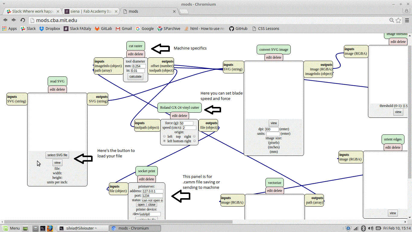
A new page opened and asked me which machine I was using and for what ( I wanted Roland vinyl cutter).
The screen then displayed several blocks and wires:
 Therafter I followed the steps both for .svg and .png files.
.SVG
I pressed on "select .svg file" and opened the one I wanted.
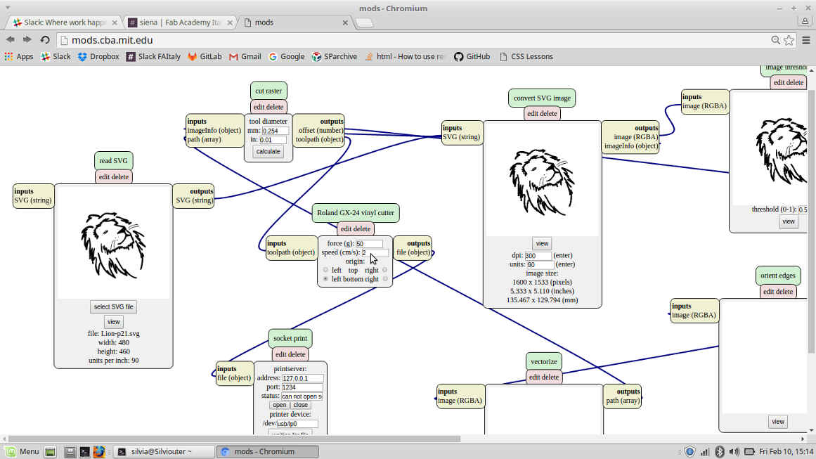 I then edited speed, force and origin position of the blade and pressed on "send file to printer" button.
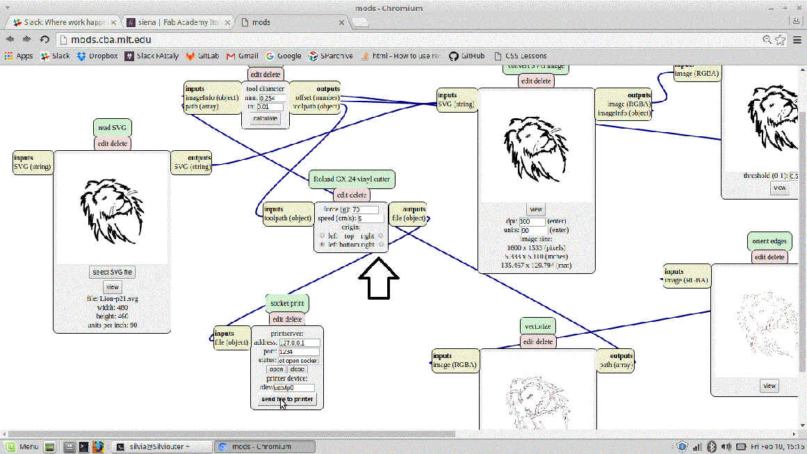
.PNG
Differently I could have wanted to use a .png file, but steps to follow are the same.
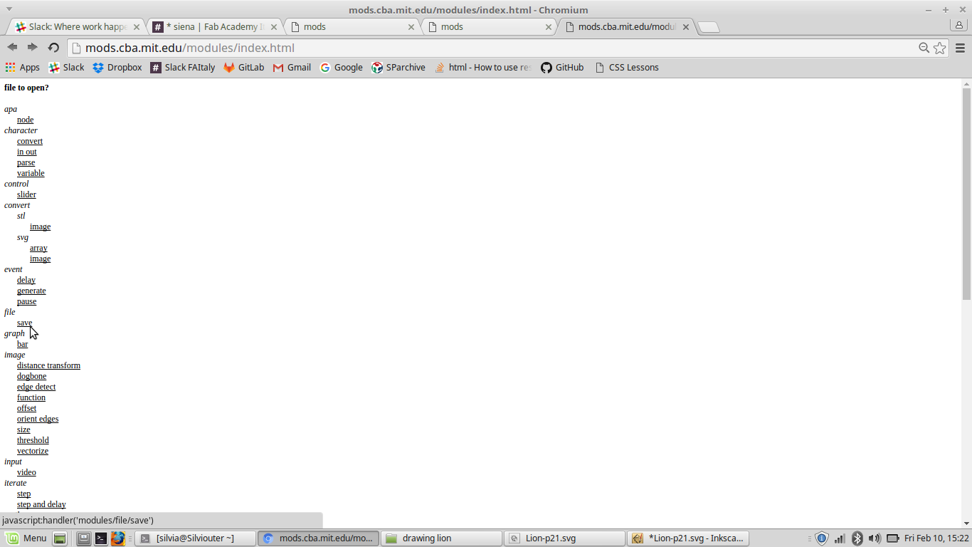
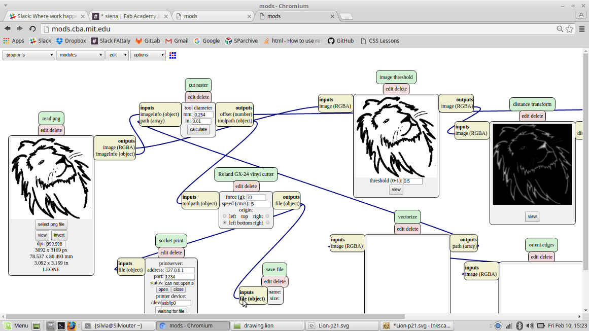
In case I wanted to save .camm file instead of sending it to printer, I would have had to press on "module"-->"add server module"
in the upper fields of the screen.
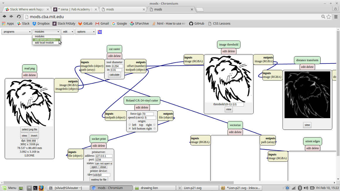 Then choose "file"->"save".
 As a new block appears on the screen and it's necessary to put it in the right position
(to do that check input and output of the block to insert and of the ones already linked).
As a new block appears on the screen and it's necessary to put it in the right position
(to do that check input and output of the block to insert and of the ones already linked).
 Once file is saved, shell commands described earlier have to be run:
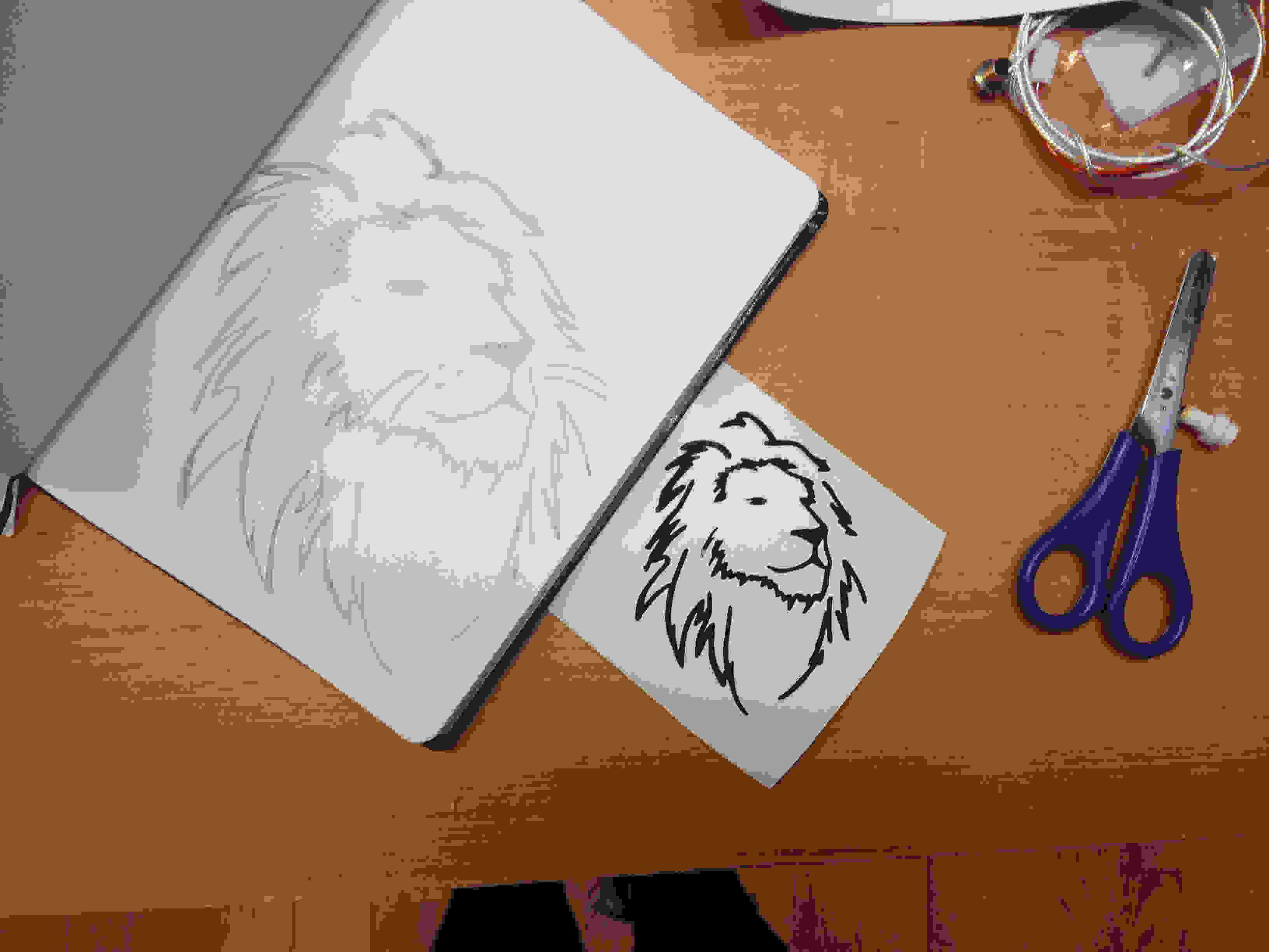
Below there's drawing-sticker comparison:
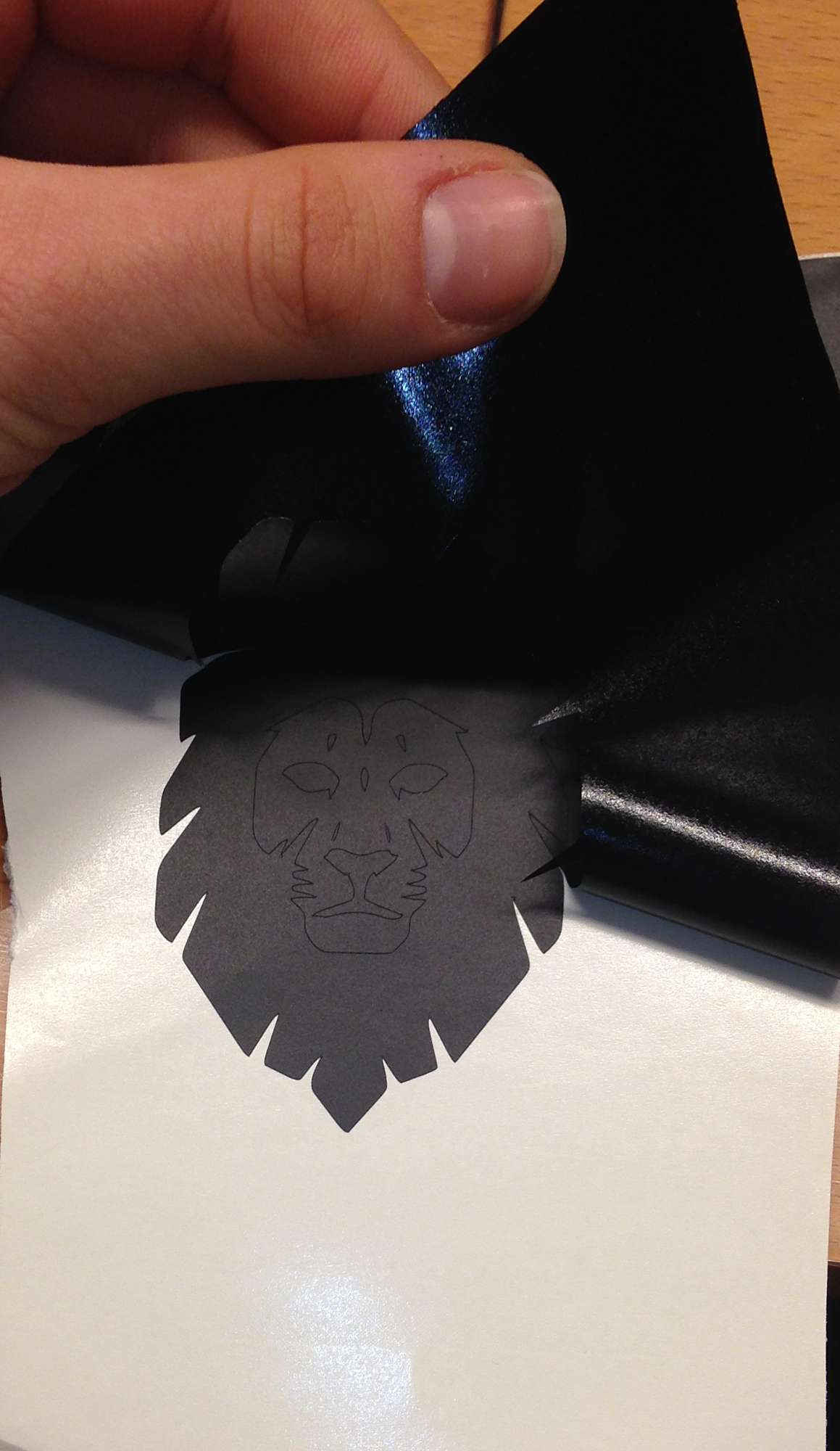
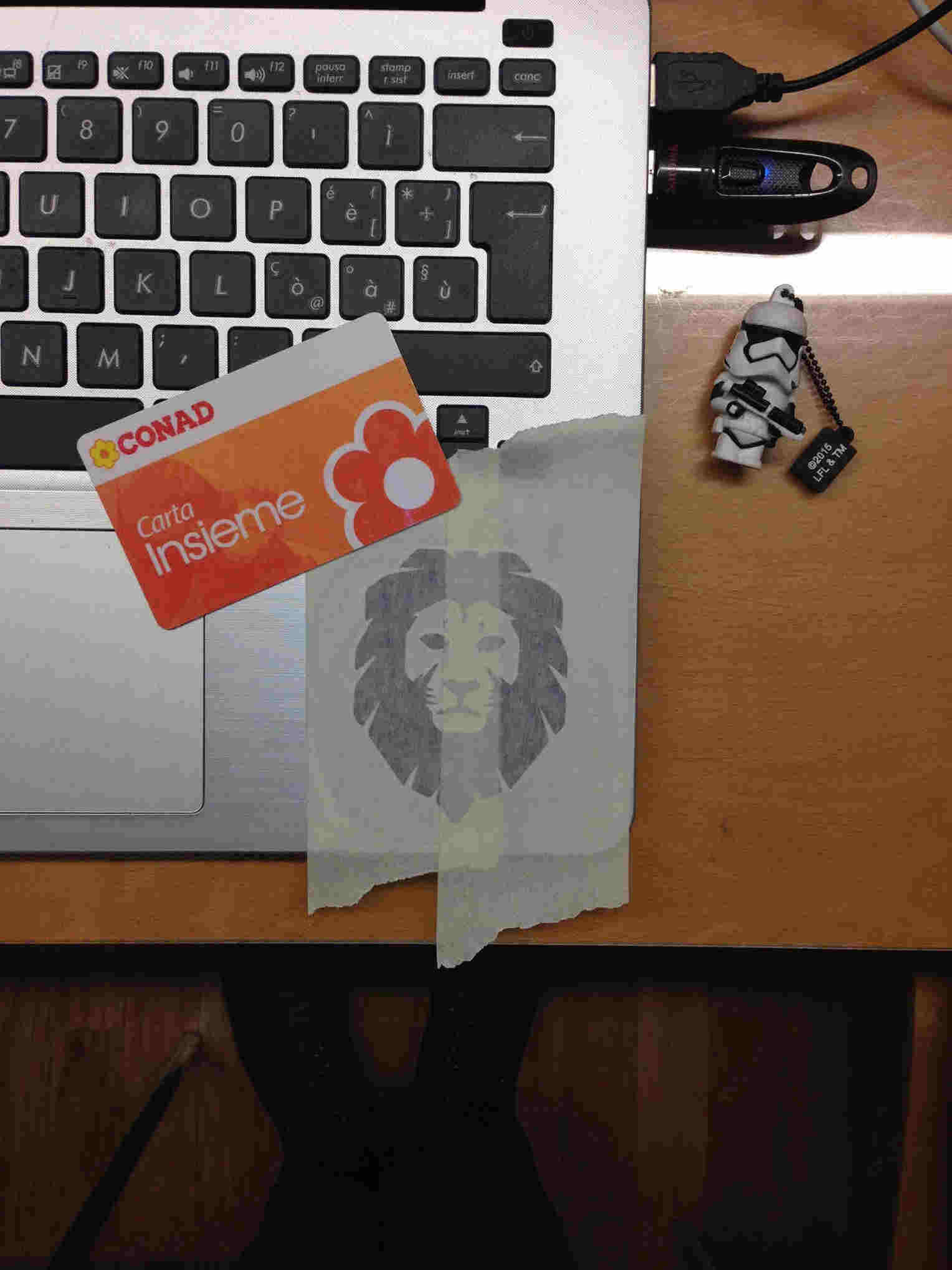
How to transfer a vinyl sticker if you don't have transfer
Since the transfer we ordered was faulty, my friends and I had to make do somehow: we used common masking tape.
Steps I follow are:
- Remove external part of the drawing in your vinyl piece;
- Put masking tape on remaining vinyl
- Make them firmly stick together (I used a shopping card to slither heavily on the masking tape)
- Remove rear white support paper of the vinyl
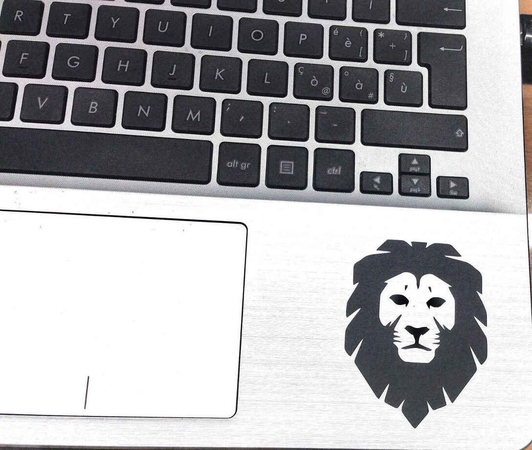
- Place the sticker where I wanted to glue it and slither heavily again
- Remove gently masking paper
NB: you may need pincers or a sharp tool to let tiny parts stick well.
Laser cutting: drawing a parametric sketch
Second part of weekly assignment was making acquaintance with laser cutting technology.
First we had to co-work in group to test kerf - you can find our group work here.
Our lab owns a Trotec 400 Speedy flex .
Useful related docs:
Parametric design: sketching with equations on Solidworks 2016
After kerf testing, we had to develop a parametric design of a press-fit kit to create for third week assignment.
It took me one day or two clearly understand what a "parametric design" really was but after many examples,
tutorials (a nice one here)
and support explanation (here)
I passed from theory to practice.
I decided to use Solidworks because I'm familiar with this software but I had never used Equations
to drive my sketch so I thought it would have been easier to check if the assembly of my sketch worked well
I intended to first test a simple joint and only after to design a press-fit parametric kit.
Testing parameters with kerf and joint
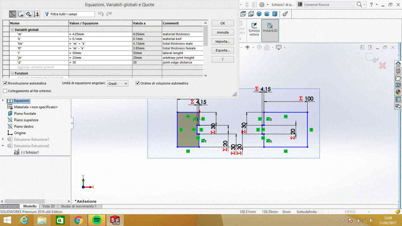
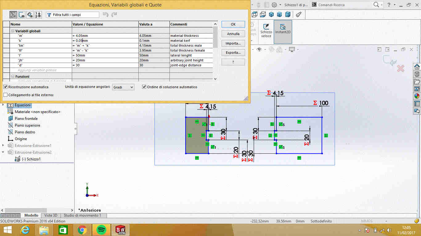
Opening a new Part, you can start setting sketch parameters right-clicking
the Equations folder in the FeatureManager design tree, and select Manage Equations
or by going in Tool-->Equations.
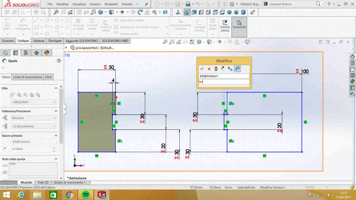
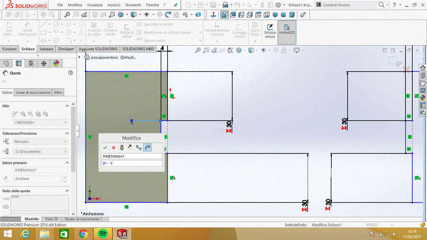
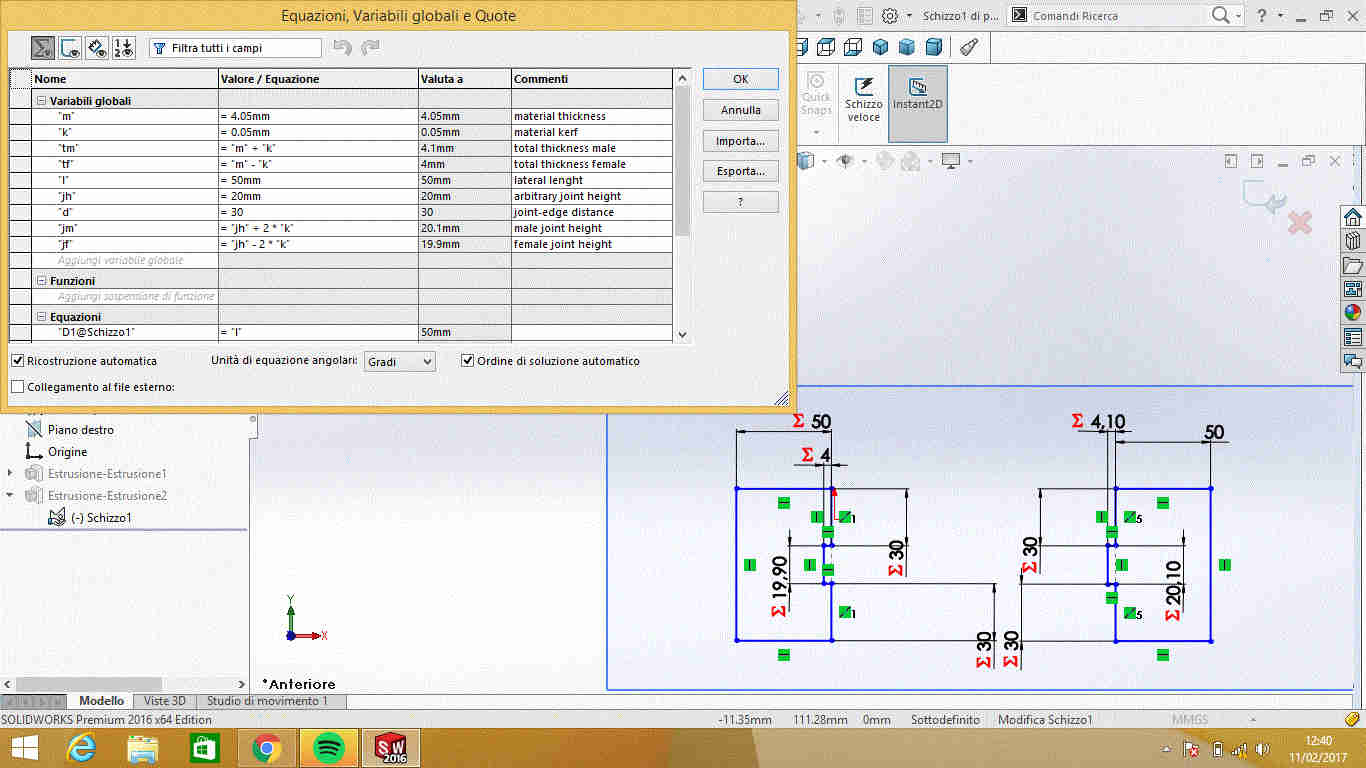
I show below the parameters I set:
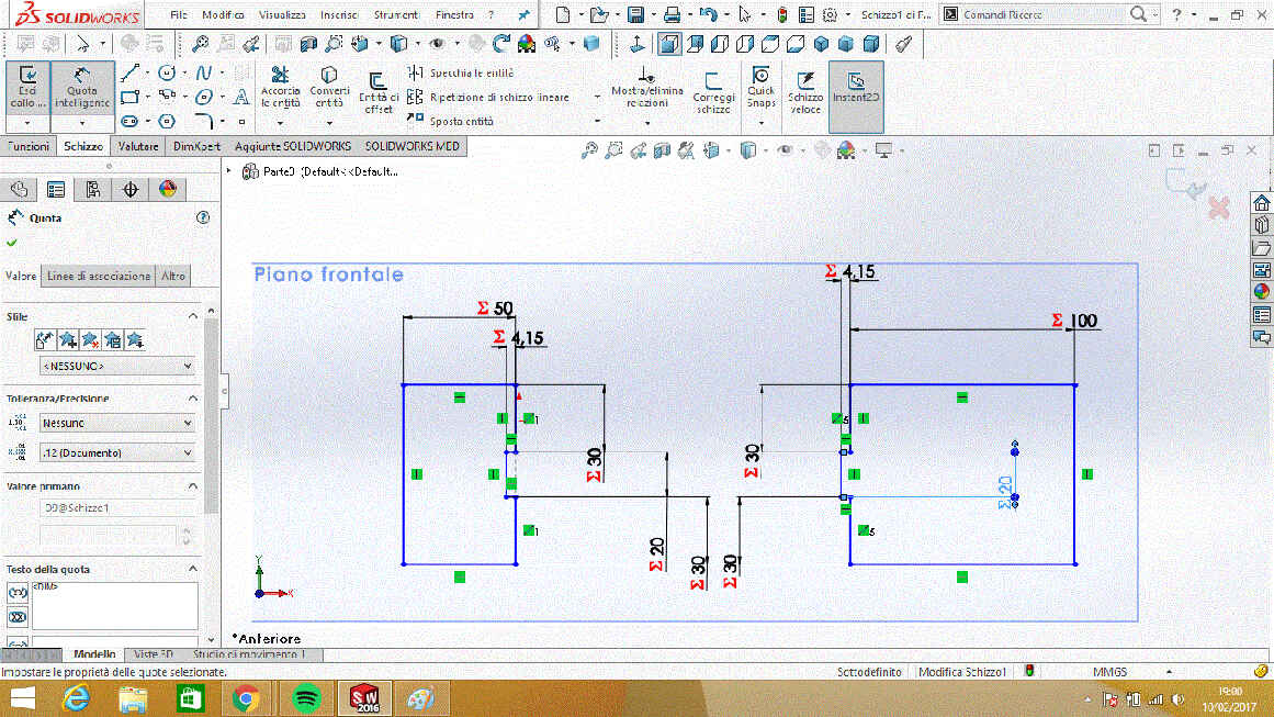
 and then I made a simple joint sketch:
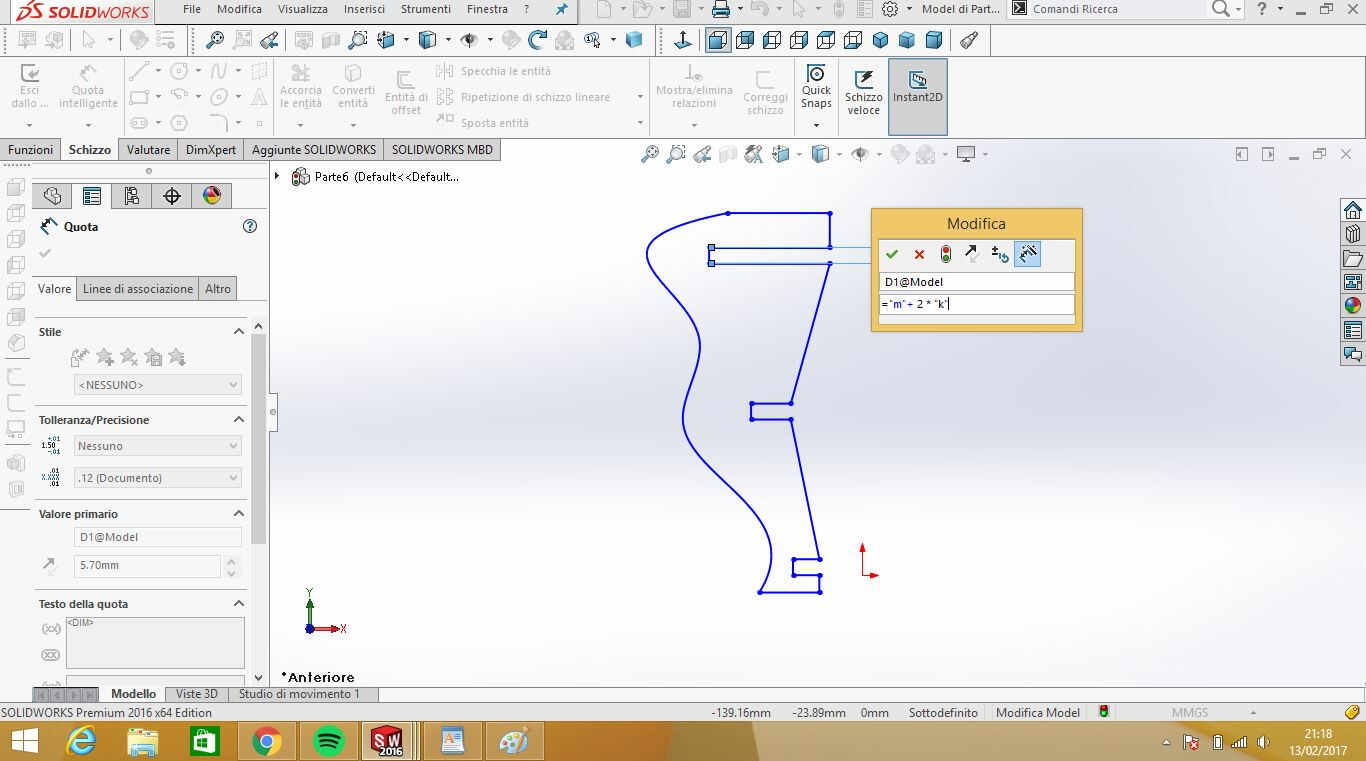
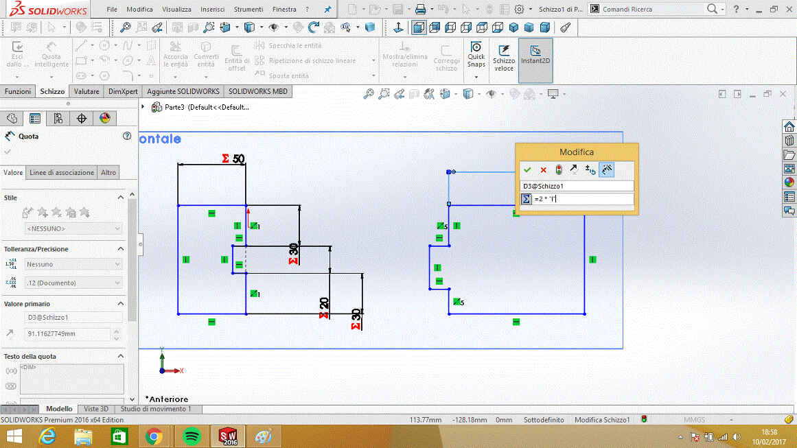 NB: in quotation window it's important to type "=" before parameter's name.
If quotations and parameters are properly defined, if you change parameters value, dimensions of the sketch will change.
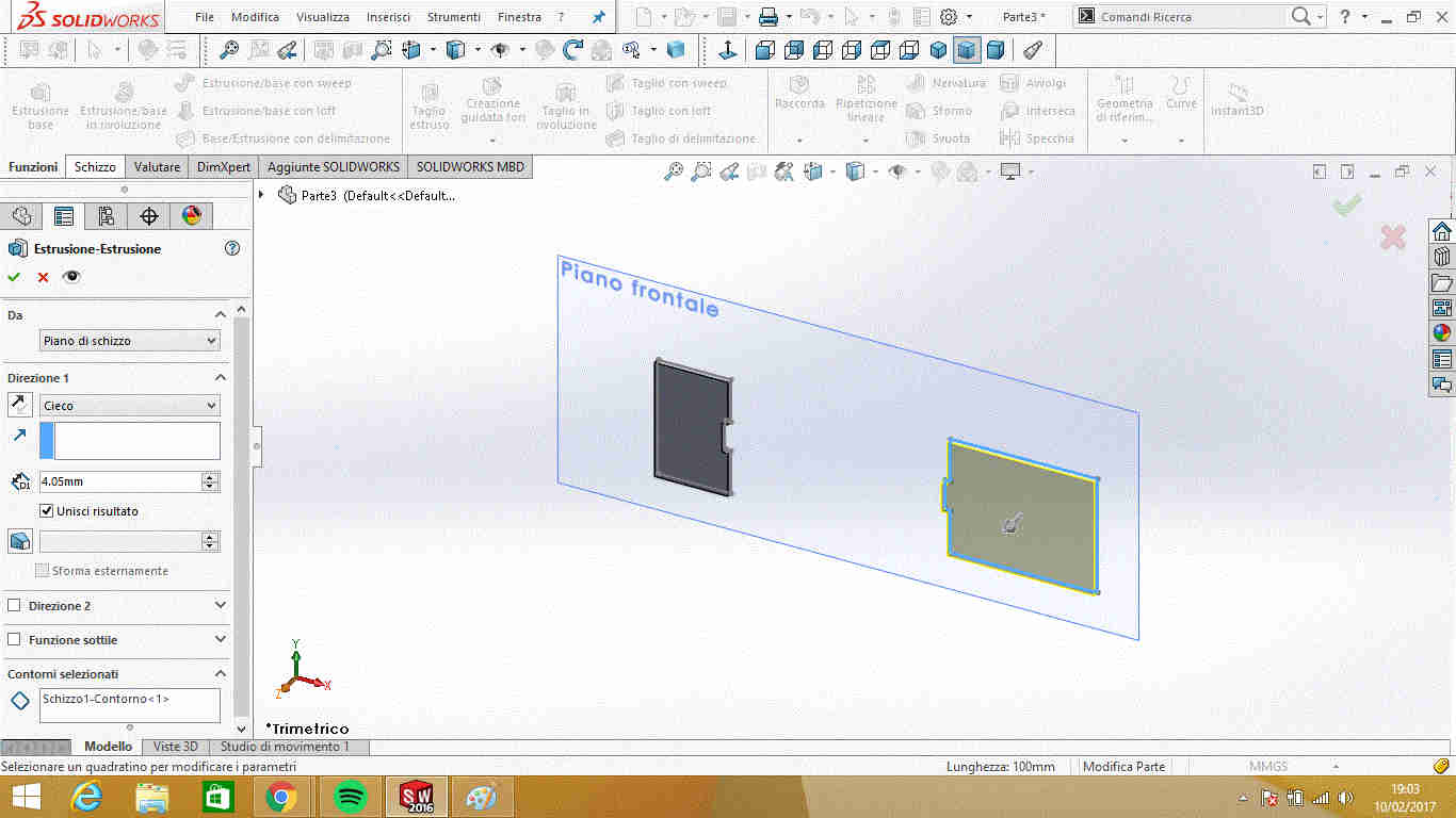
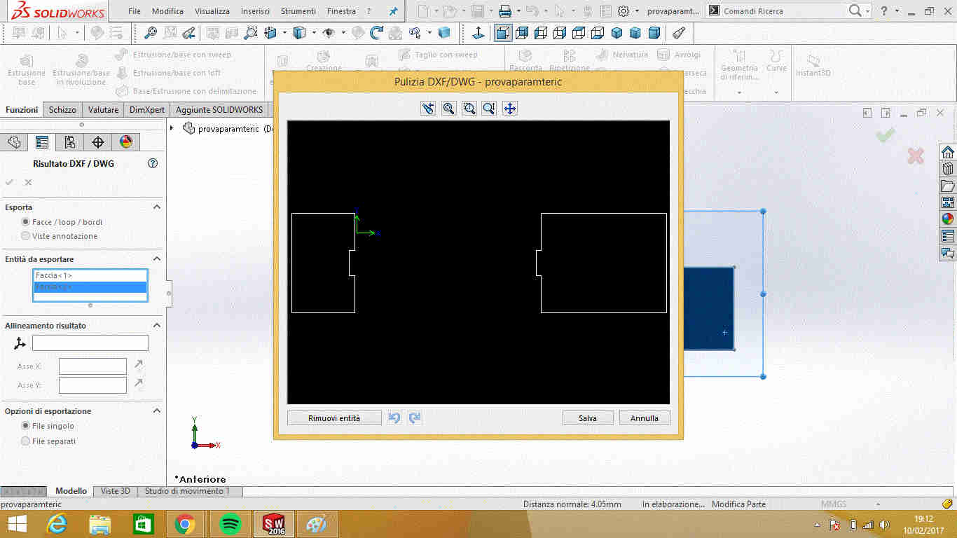
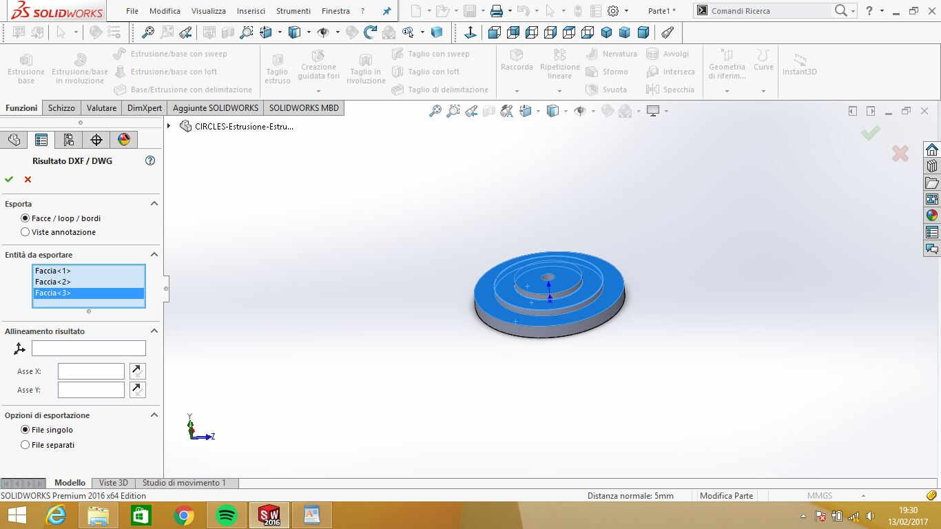
It is necessary to save drawing as a .dxf file to send it to the lasercutter and to do so you need to
extrude your sketch before (you have to select faces to export as dxf file).
First attempt I made was with 0,1mm kerf (I hadn't test prototype material real kerf).
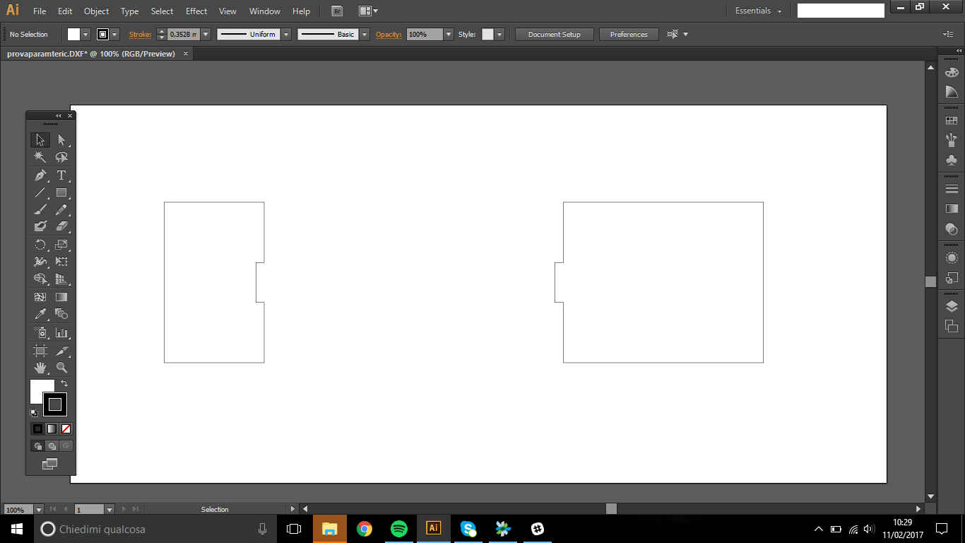
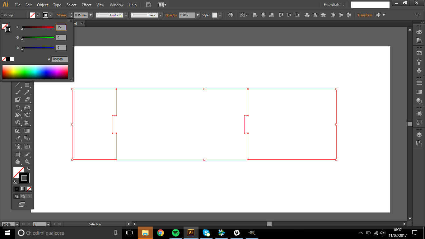
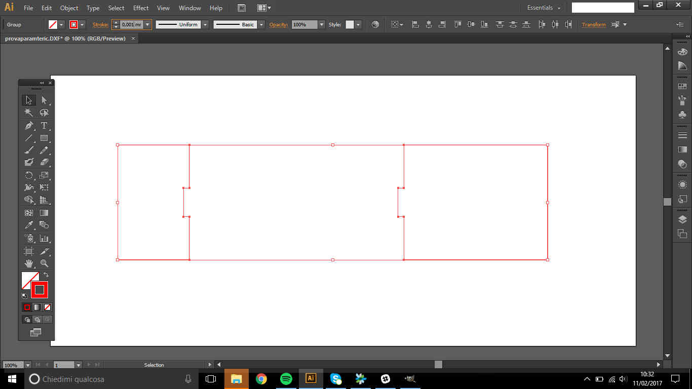
I opened .dxf file on Illustrator and I edited some file features to make it suitable for the laser cutter:
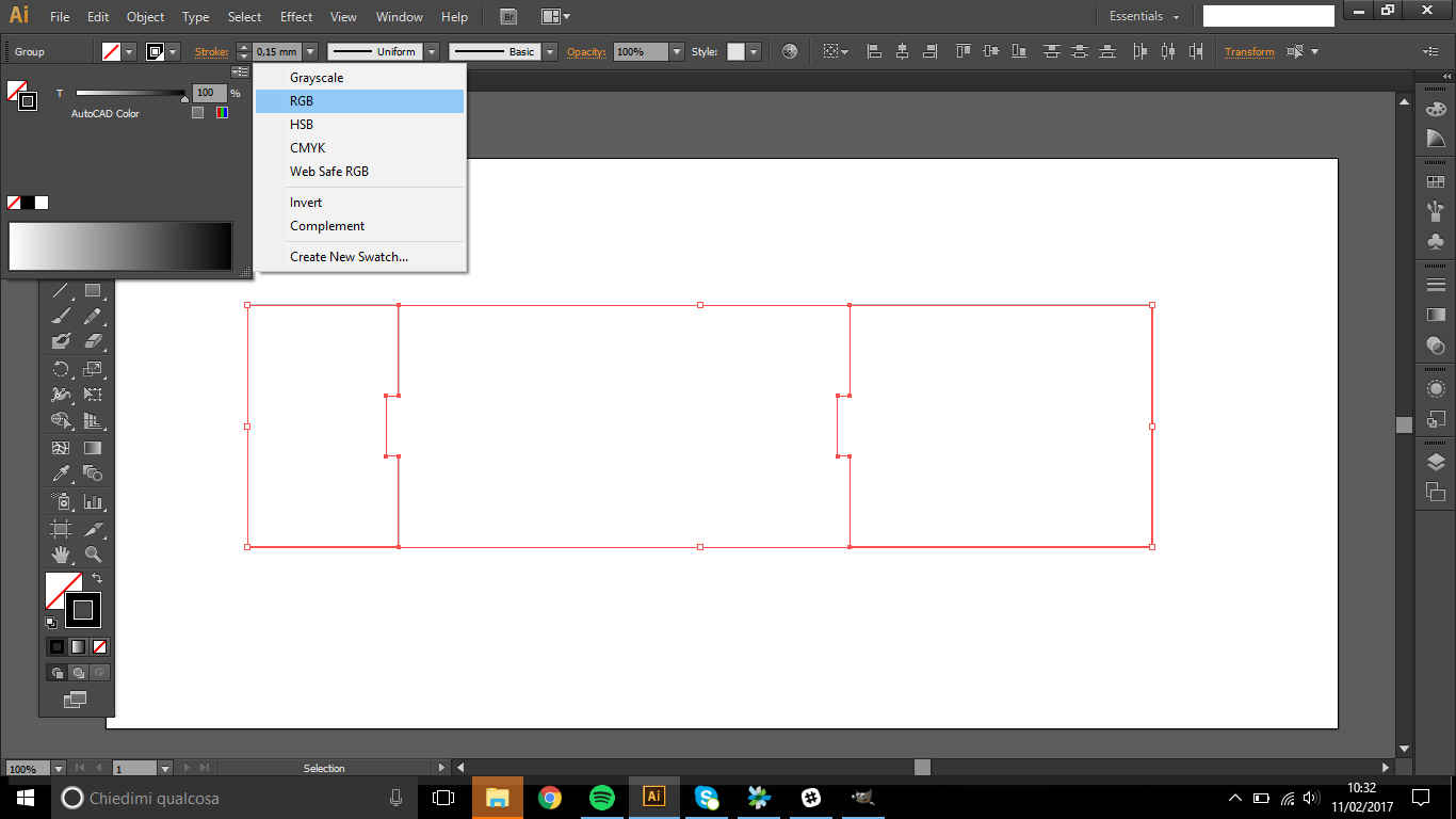
- Changed boundaries RGB and thickness (because laser cutter software recognize specific values- that can be changed anyway)
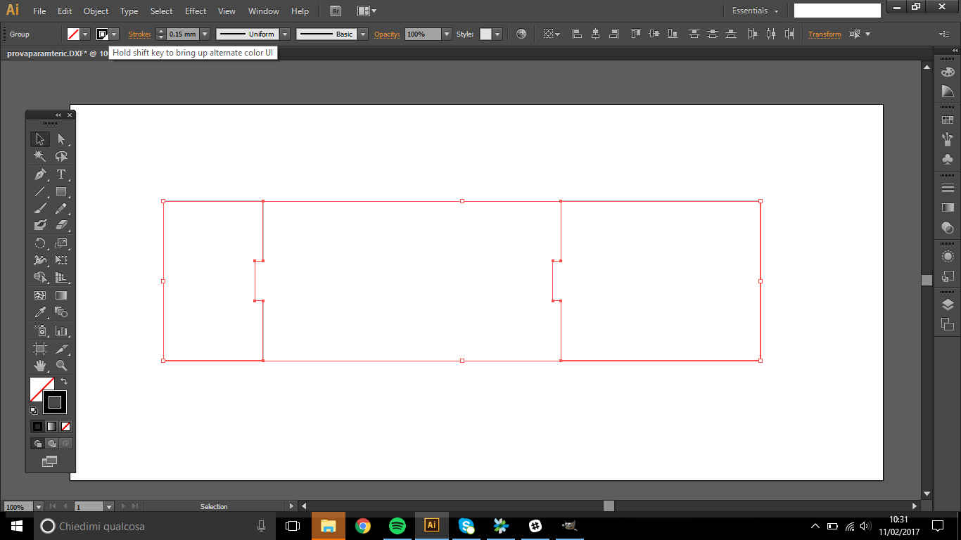
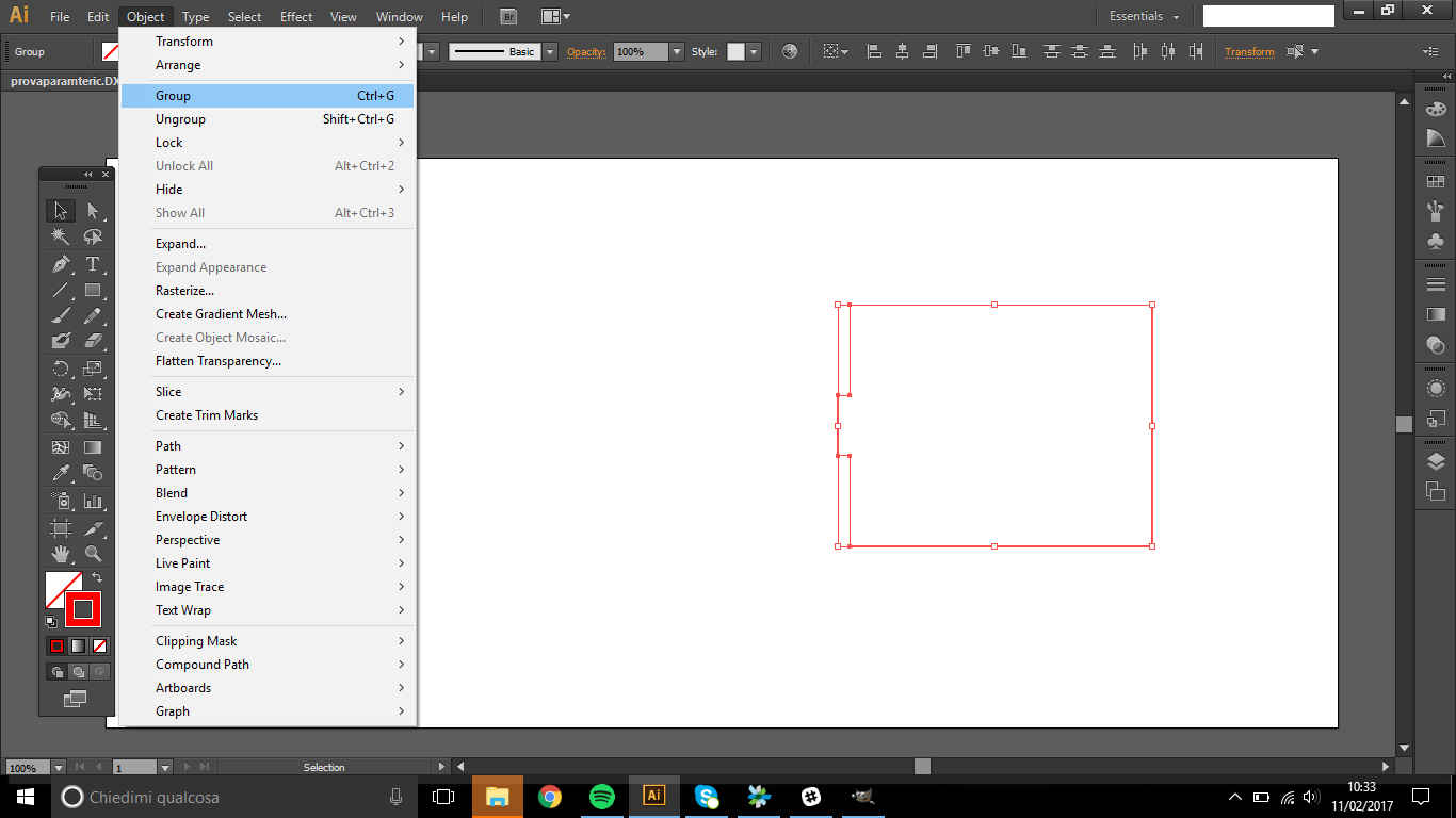
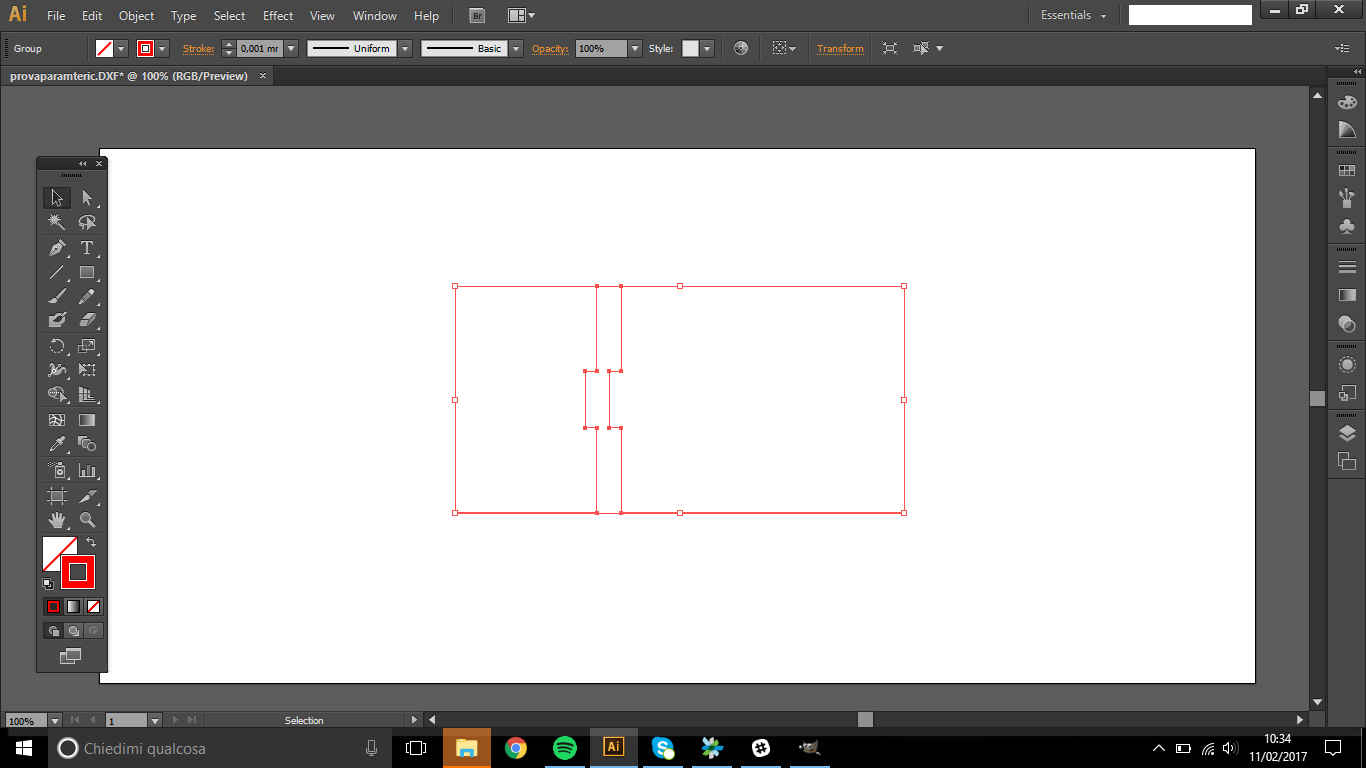
- Grouped (Select element and Ctrl+G) and moved closer:
- edit printing features:
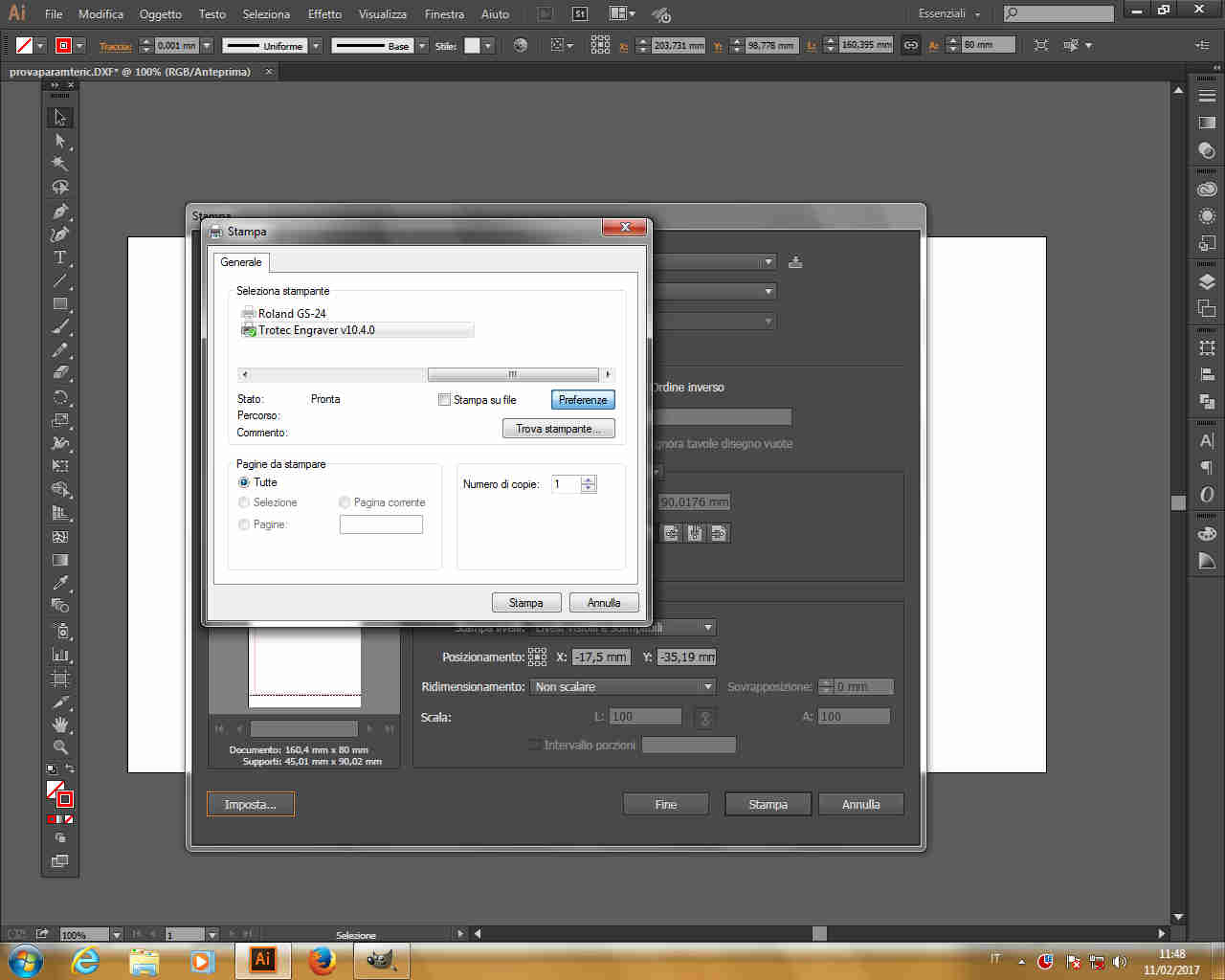
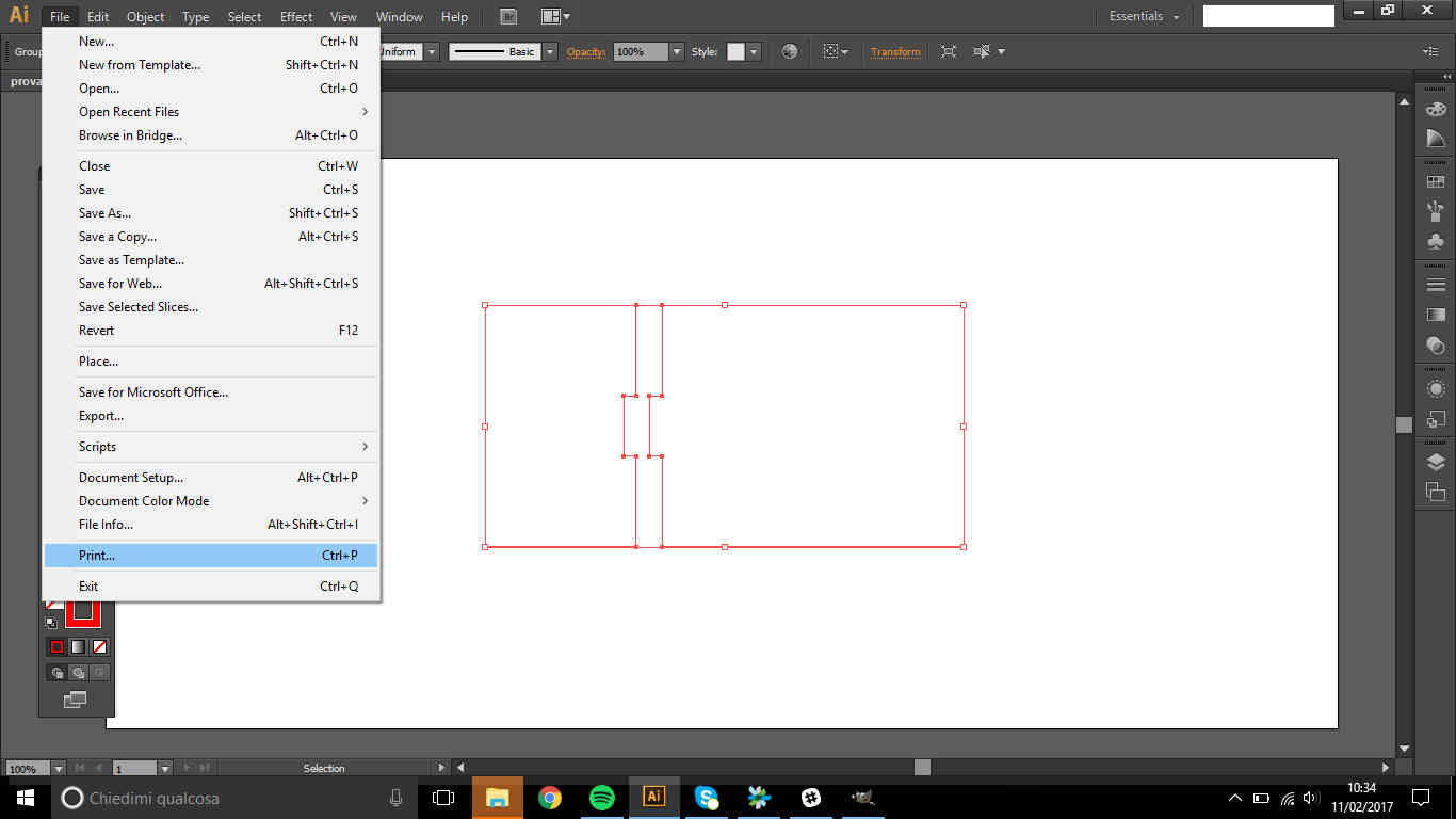 1-Select printer ( your laser cutter name in orange square):
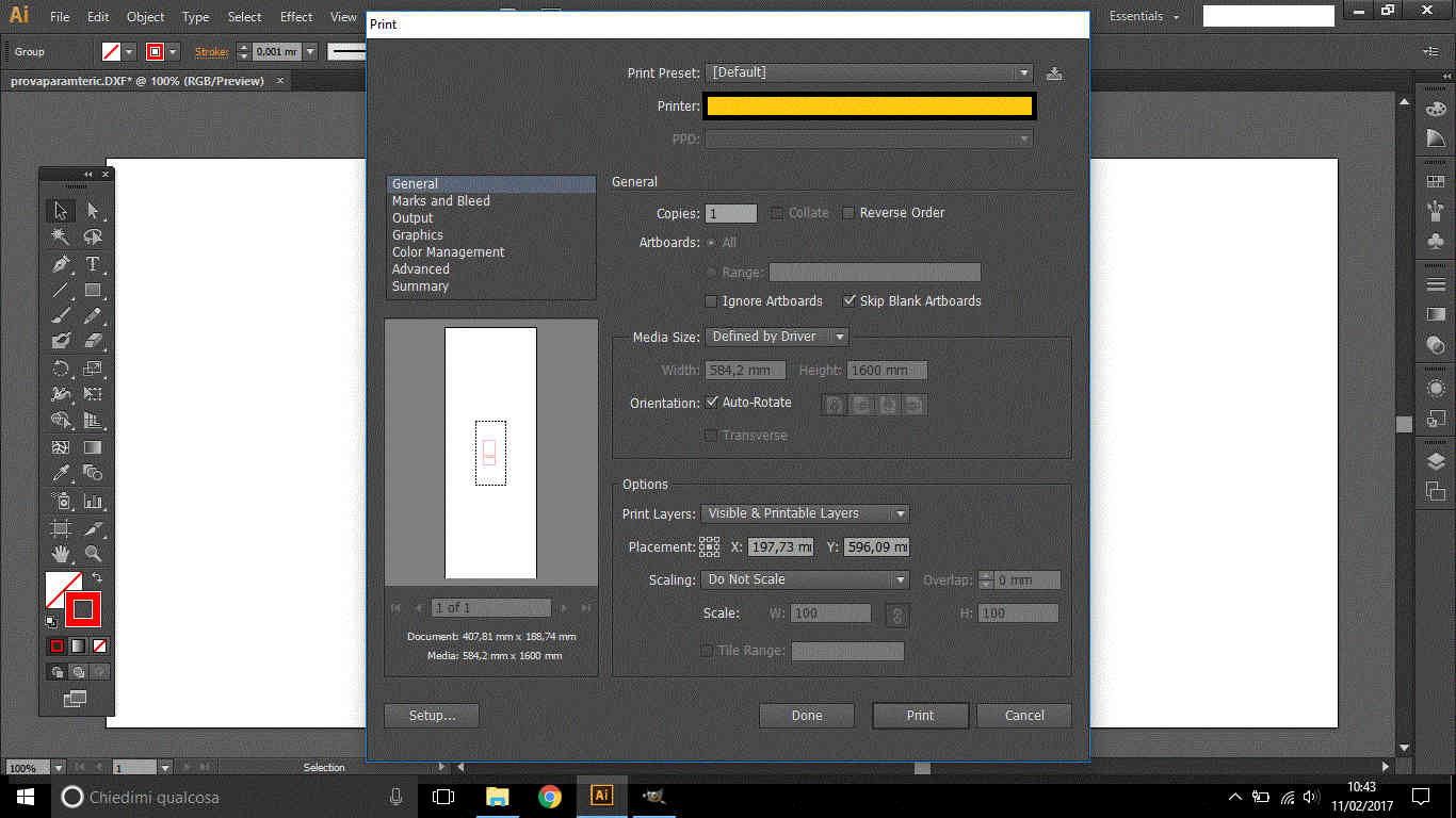 2-Tick Ignore artboard:
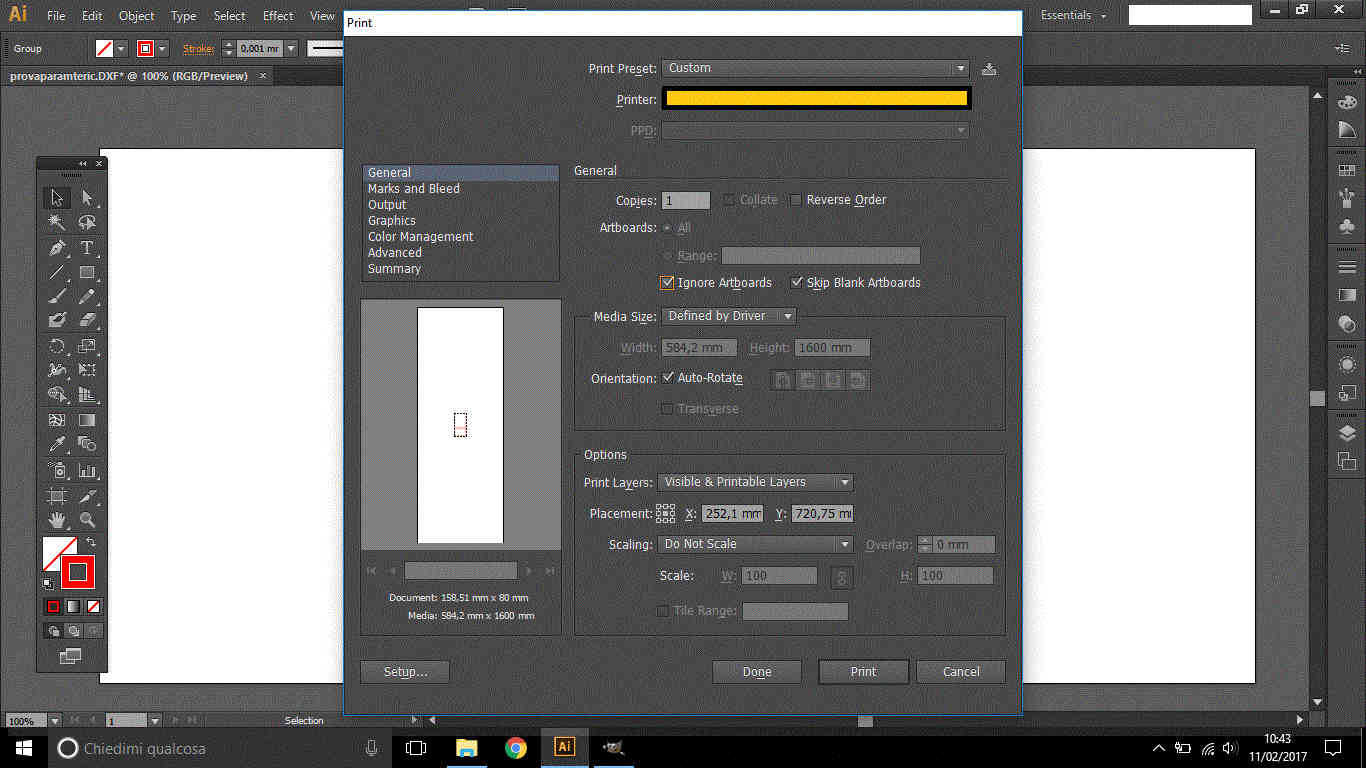 3-Untick Auto-rotate:
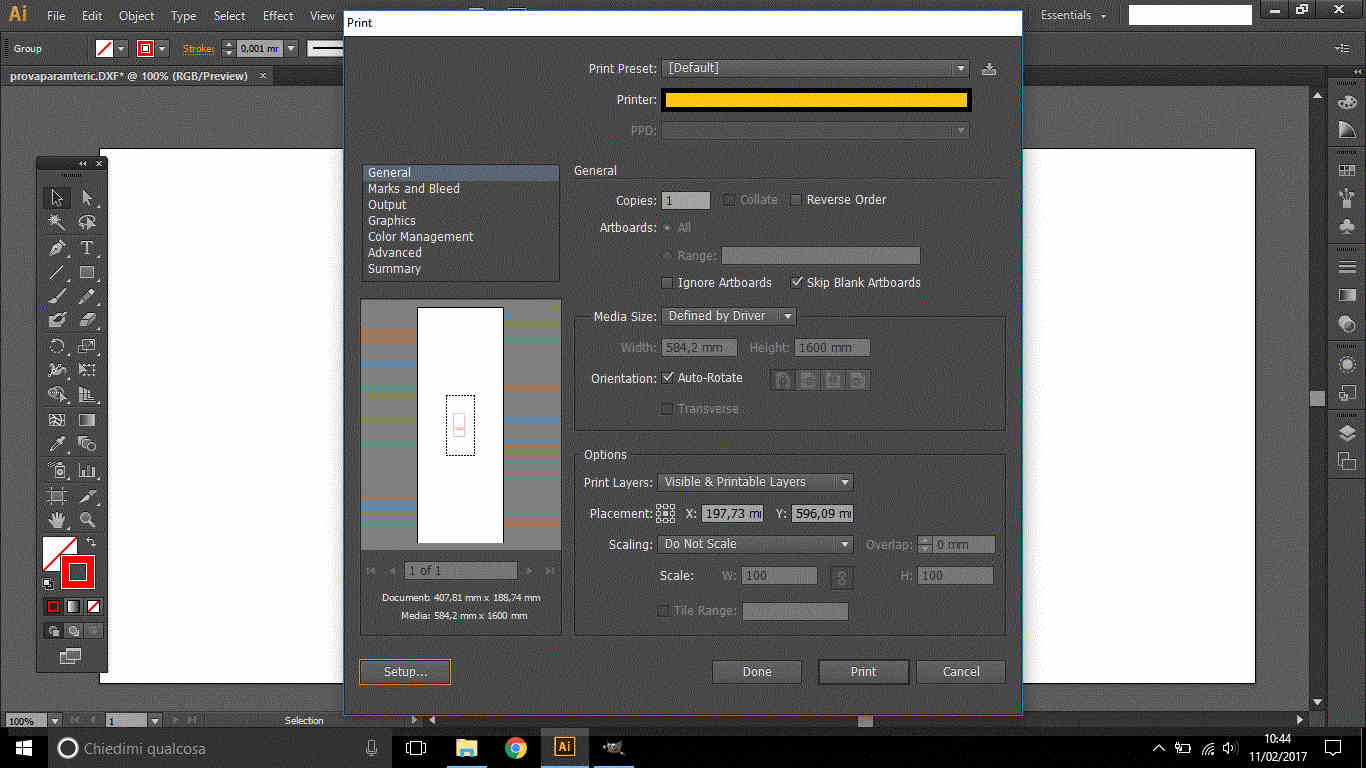
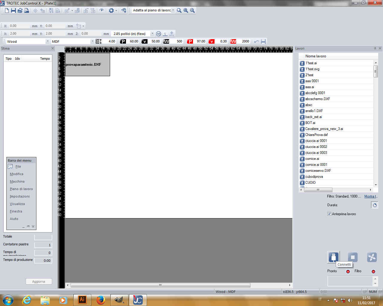
 4-Click on Setup to run laser cutter's software ( Job Control in my case):
 (sorry that on my lab notebook Job Control is set in Italian language)
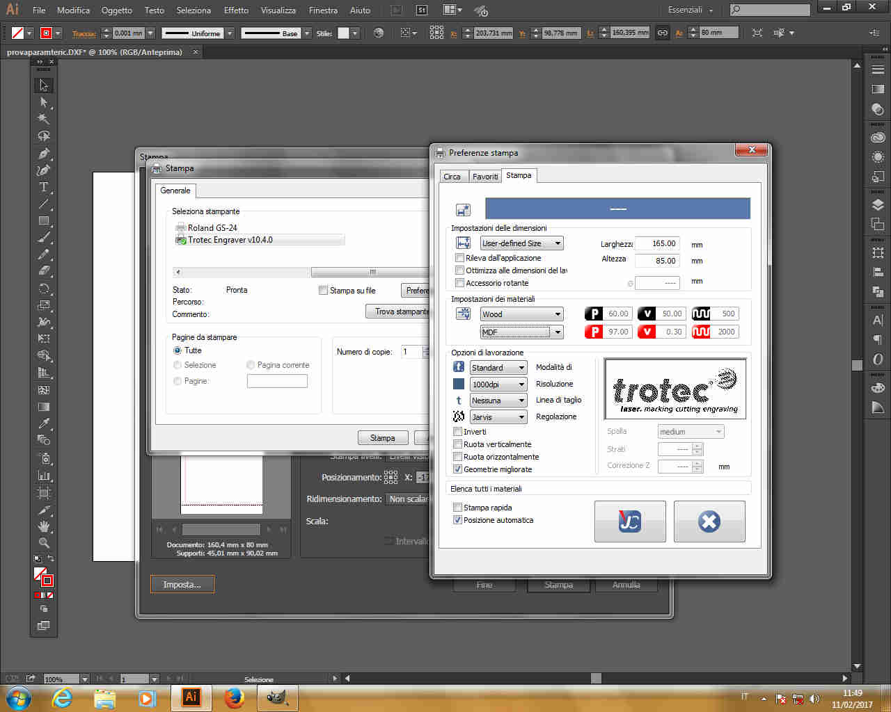
 5-Clicking on Preferences it's possible to make changes based on document dimensions (written above Setup) to workspace area.
 NB: I usually leave 5mm margin more or left.
6-Set material and click JC button (means "print")
NB: I usually leave 5mm margin more or left.
6-Set material and click JC button (means "print")
Job Control will open automatically and your work will be already on work area.
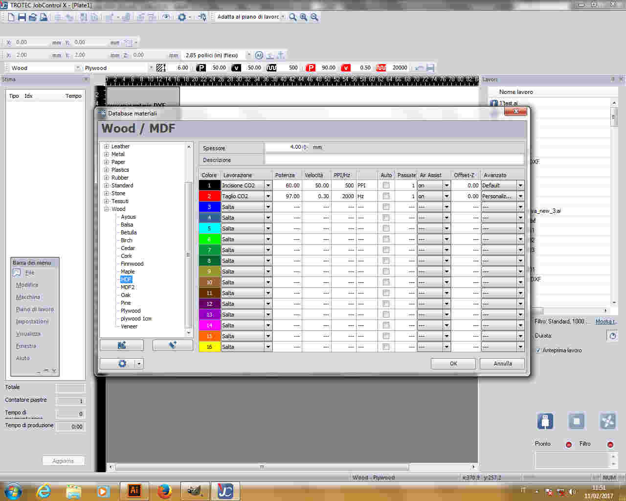
By double-clicking on free space you can edit material and set action (cutting or engraving) RGB, power, speed and ppi
(that's why we changed RGB of .dxf file on Illustrator before).
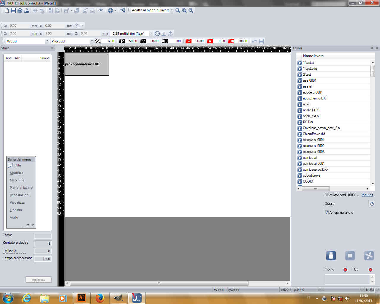
 To connect to the printer you have to press on USB sign in bottom right of the page:
 Then drag and drop your work till the laser pointer.
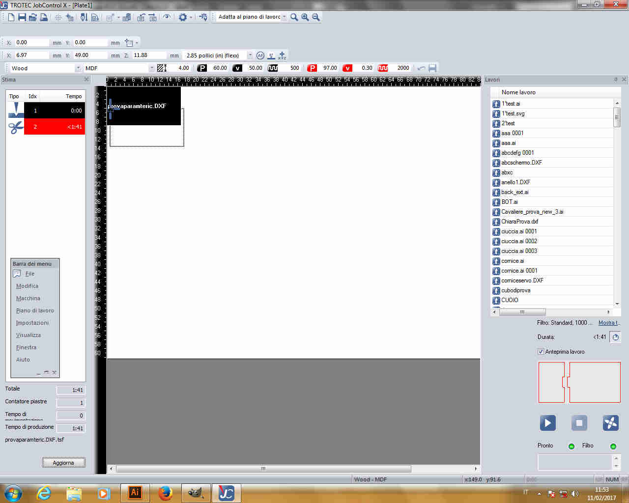 Pressing Ctrl+I you'll see your work preview. If you see like this:
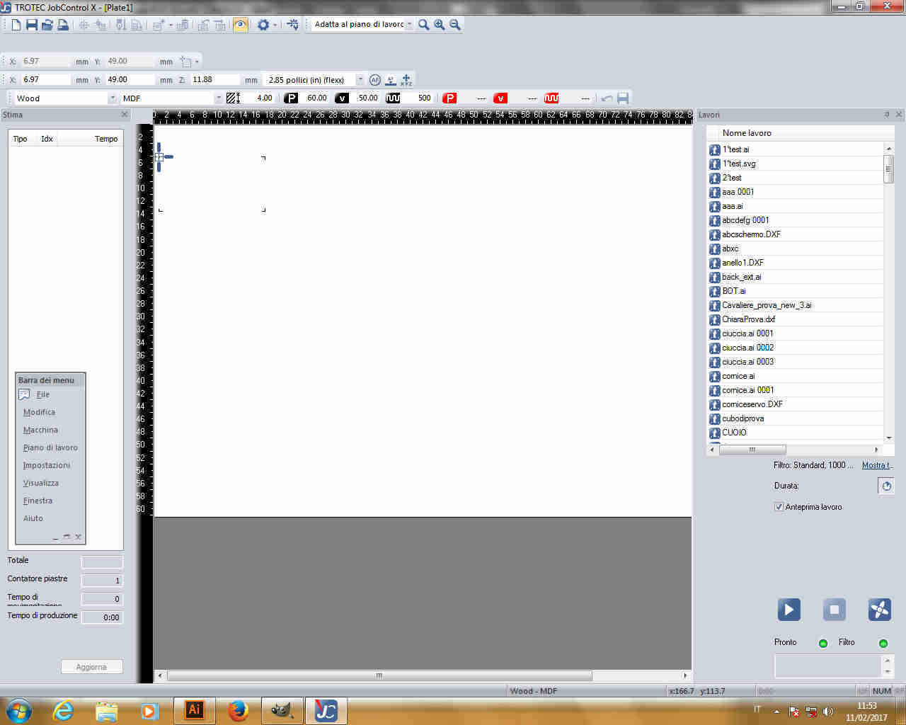 it means the color you used on Illustrator doesn't correspond to any action on Job Control, otherwise you'll see something like this:
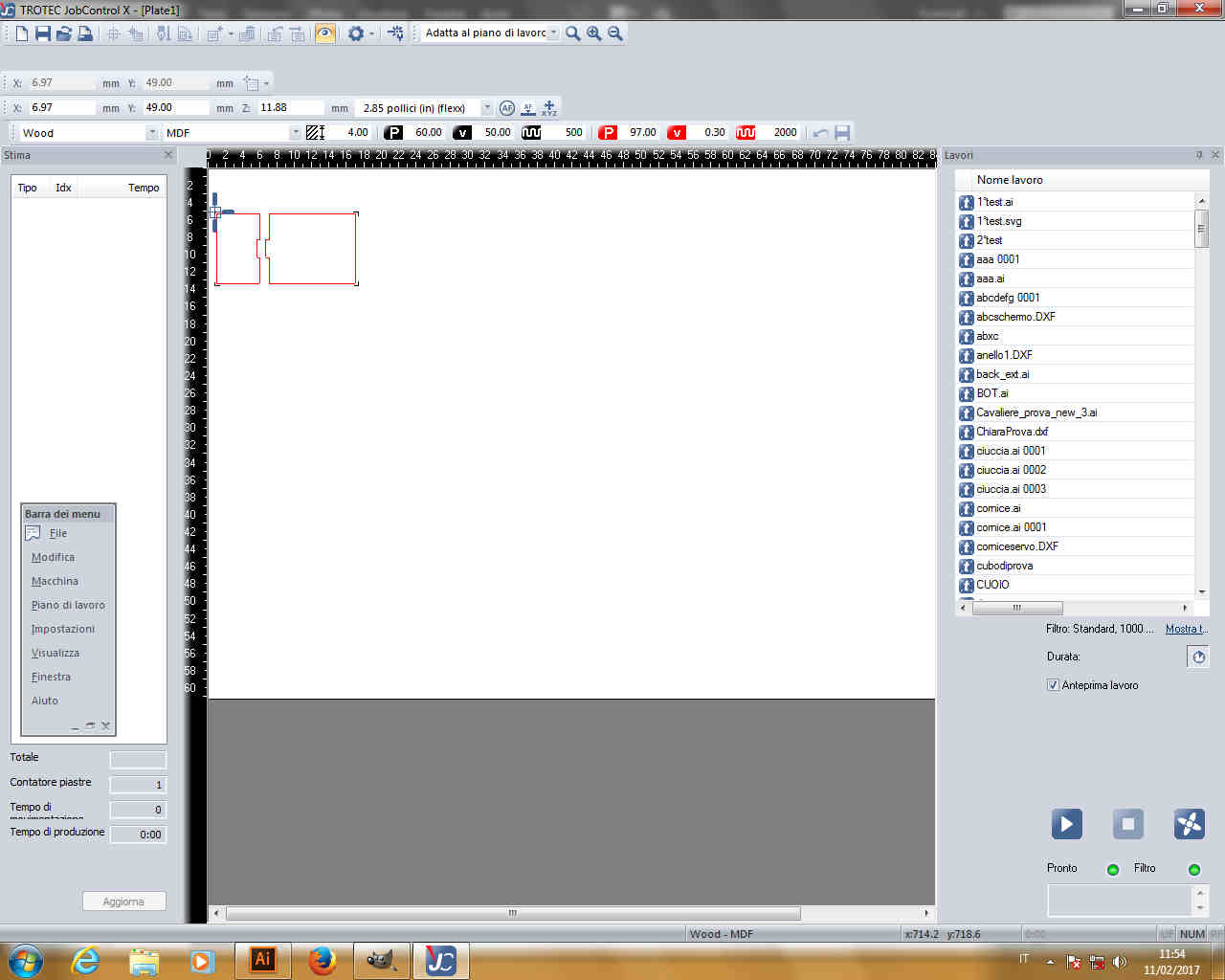 If material features are properly set, you can run your work pressing "Ready" button on bottom right.
IMPORTANT: make sure laser focalization is ok!
Brief explanation on how to set Trotec 400 Speedy flex
I think most of laser cutters require the same process to be launched.
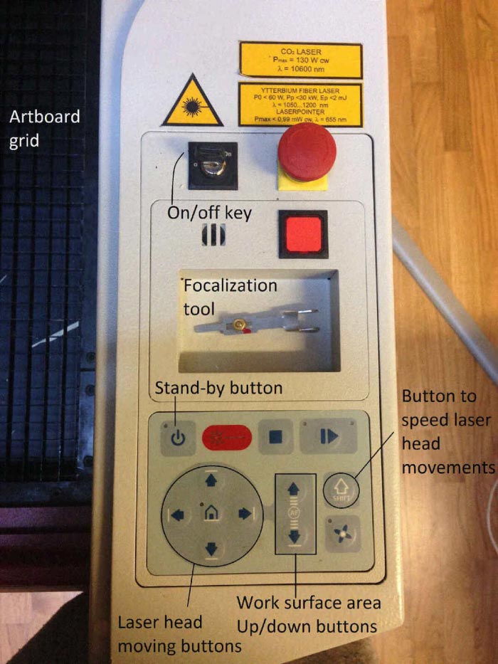 This is Speedy 400 Flex keypad.
- Switch the machine on turning on-off key clockwise beyond "I" sign;
- Wait till the work surface area goes down completely;
- Push the Up button of work surface area in the keypad till it is 5 cm distant from laser head;
- Put the focalization tool as shown below.
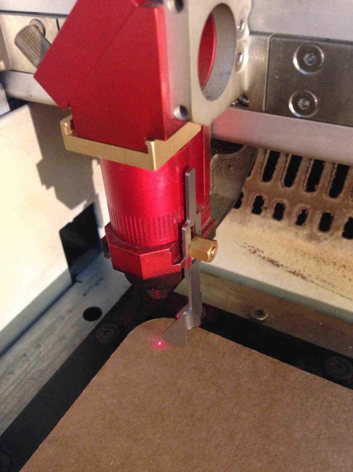
- Keep on pressing little until the tool drops of the head guide;
- The focus is set.
NB
- Be careful not to hit laser head in positioning material
- It's always better to fix material to the work area borders with masking tape (which can be easily cut by laser light)
Focus setting from Silvia Palazzi on Vimeo.
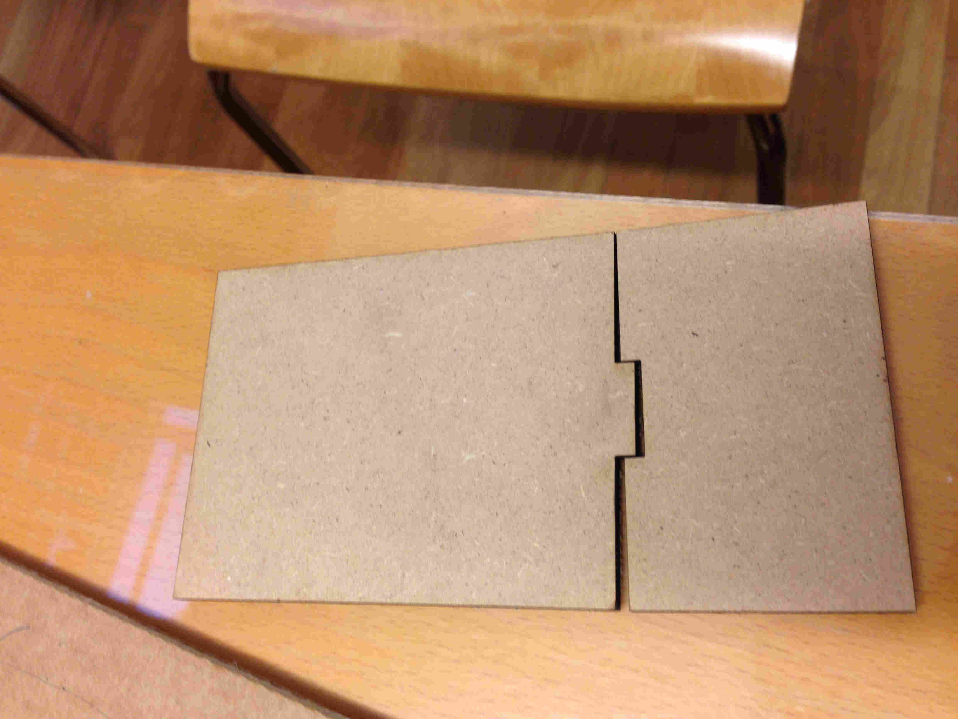
....Joint result: First attempt
Since I hadn't check real kerf of MDF (I used this material for prototyping), joint didn't work.
....Second Attempt
So I used electronic calipers to check MDF kerf: since the measurement resulted 0,1 mm bigger than file size, kerf was 0,05mm.
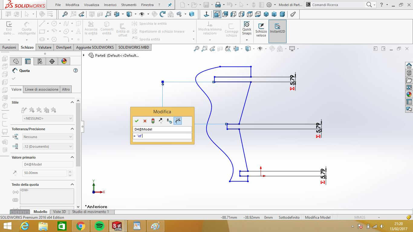
I so changed parameters value on Solidworks:
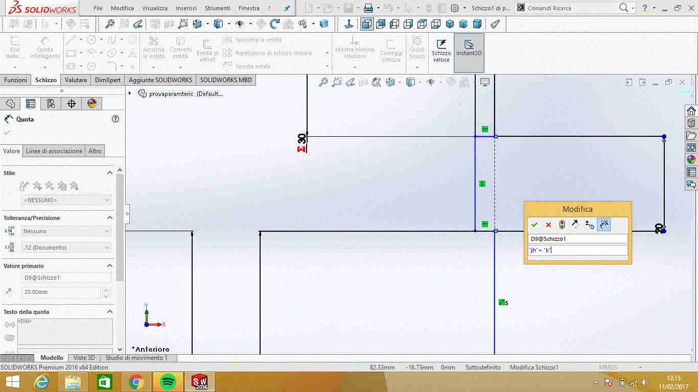 I also realised (with great help from Simone Guercio)
that in joints height kerf has to be added/subtracted two times and so I defined two new parameters:
I also realised (with great help from Simone Guercio)
that in joints height kerf has to be added/subtracted two times and so I defined two new parameters:
 I repeated the step to cut new .dxf file and the result finally matched with no play.
Parametric lamp socket: are we sure kerf really exist?
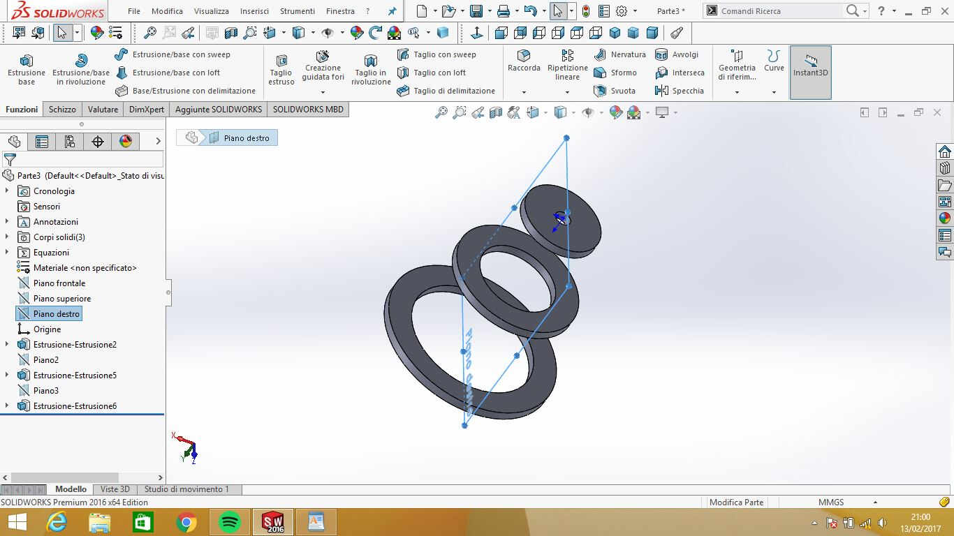
After testing joint on MDF and plywood kerf in group, I started designing my parametric modular project.
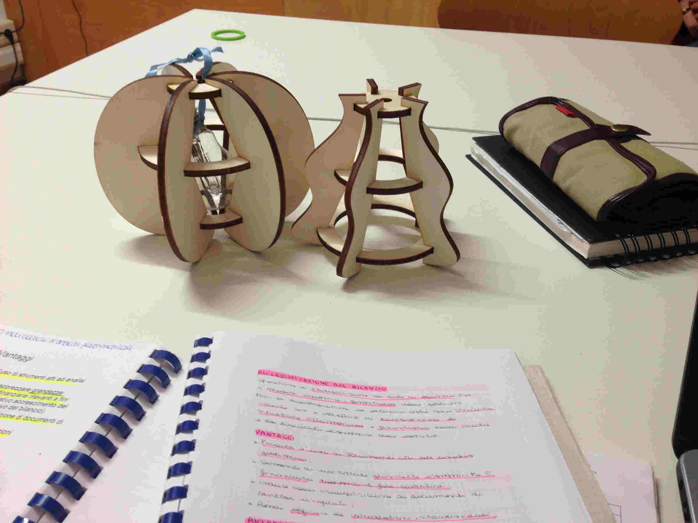
My concept was to make a lamp socket that could change shape thanks to internal structure (made of concentric
disks that could be combined vertically in multiple ways) and outer different coverings.
Instead of writing my parameters on Solidworks 2016 I wrote a .txt file with variables
and relative values and then imported it on Equations folder in FeatureManager.
I admit some parameters were added while sketching cause you better understand how to relate dimensions
just when your sketch gets sharp.
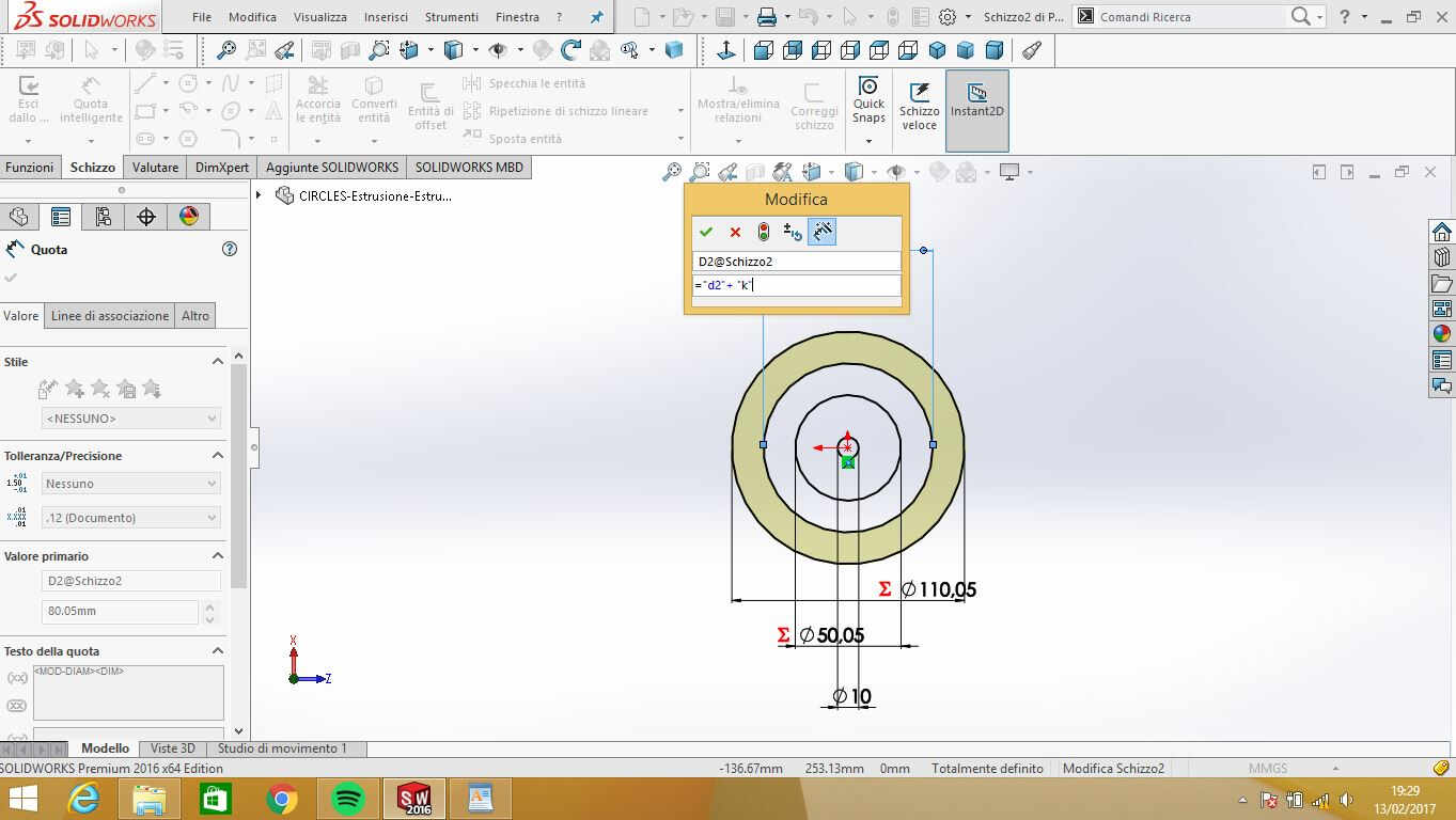
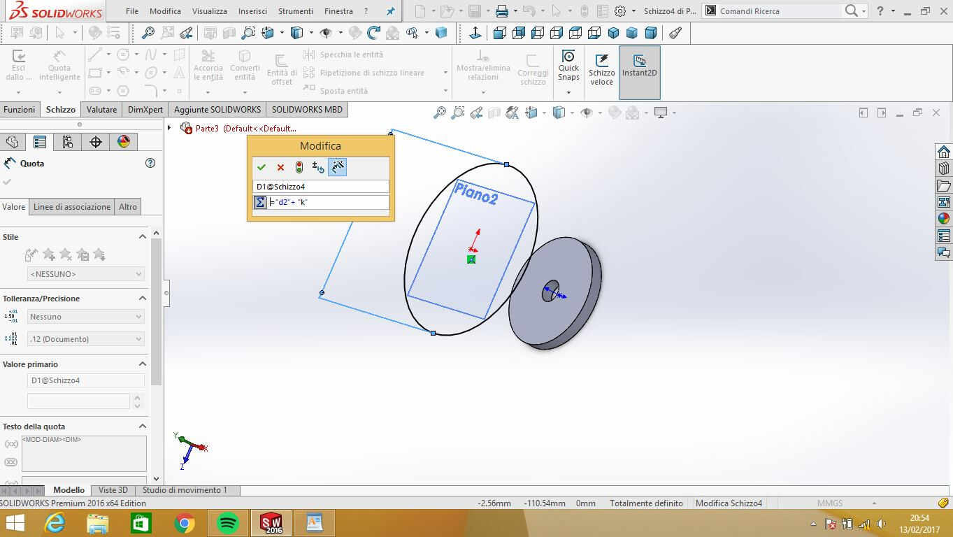
For example, when I first draw my lamp socket, I used (circles width)+kerf as parameter but then
I couldn't move easily among covering sketch definition (cause I needed diameters value to create joints),
so I assigned "d", "d2" and "d3" different values to which I after added kerf.
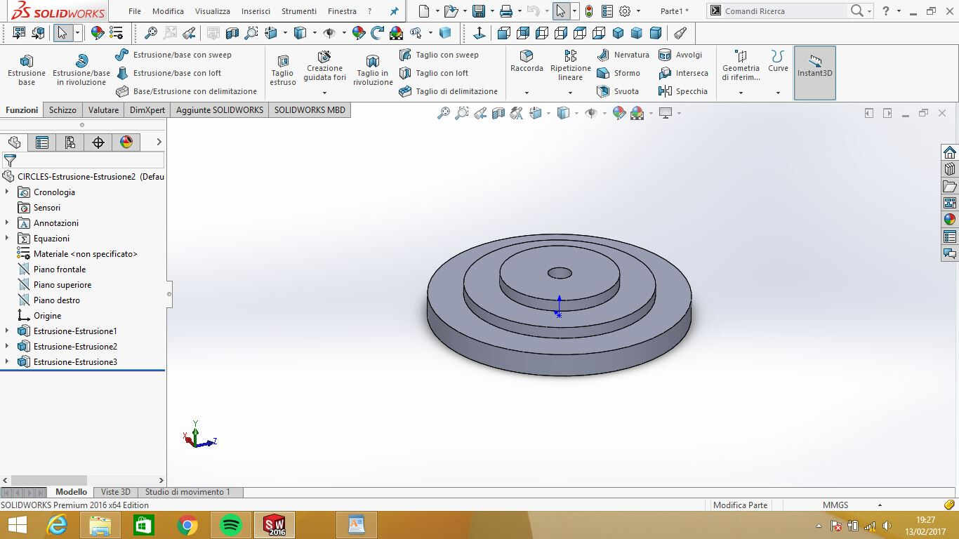
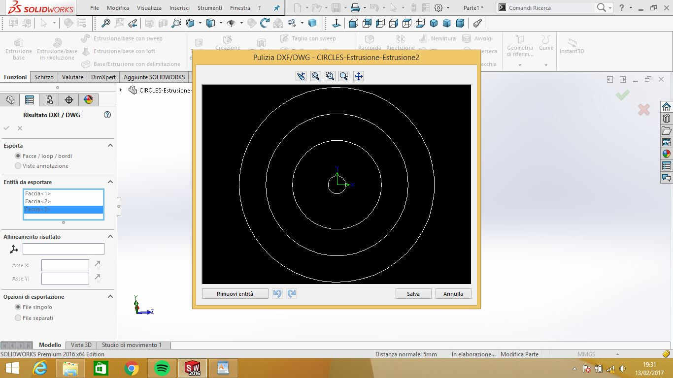
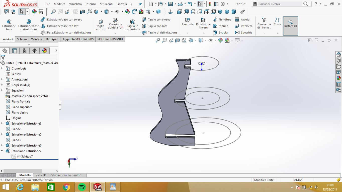
 To export .dxf file to be sent to the laser cutter, I had to extrude each circle of different height
otherwise it would have been just one solid body with one face (actually their real thickness correspond to plywood one).
To export .dxf file to be sent to the laser cutter, I had to extrude each circle of different height
otherwise it would have been just one solid body with one face (actually their real thickness correspond to plywood one).
External covering design took me more time due to these problems:
- I couldn't imagine a nice shape to give them(and you see that still I haven't found one);
- I had difficulties in replicating circles dimension while spacing them vertically;
- I wanted to be see immediately if the circles I was repeating really corresponded to previous ones.
After several attempts I found a way:
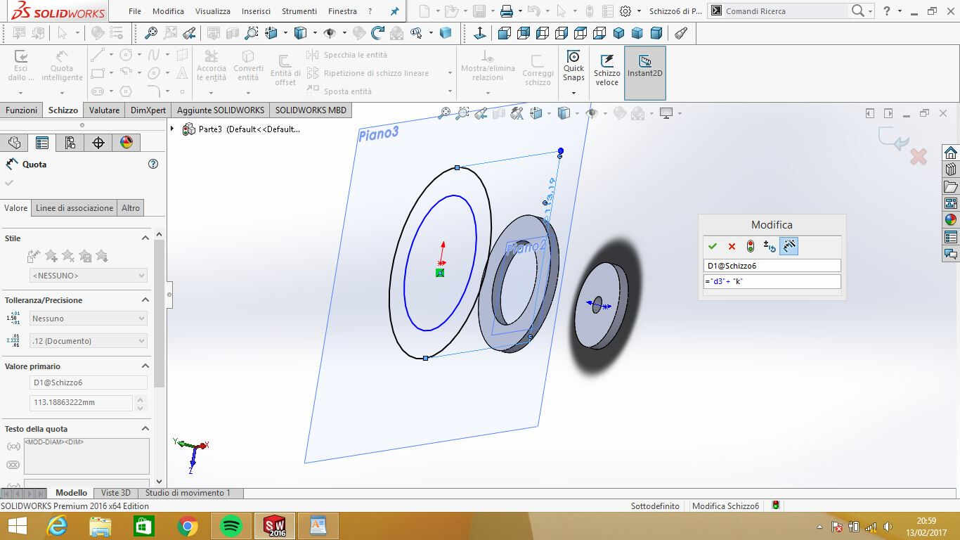
I made a new part sketch with vertically spaced parametric
extruded circles (using Reference Geometry-->Plane function):
 ...and I had this result:
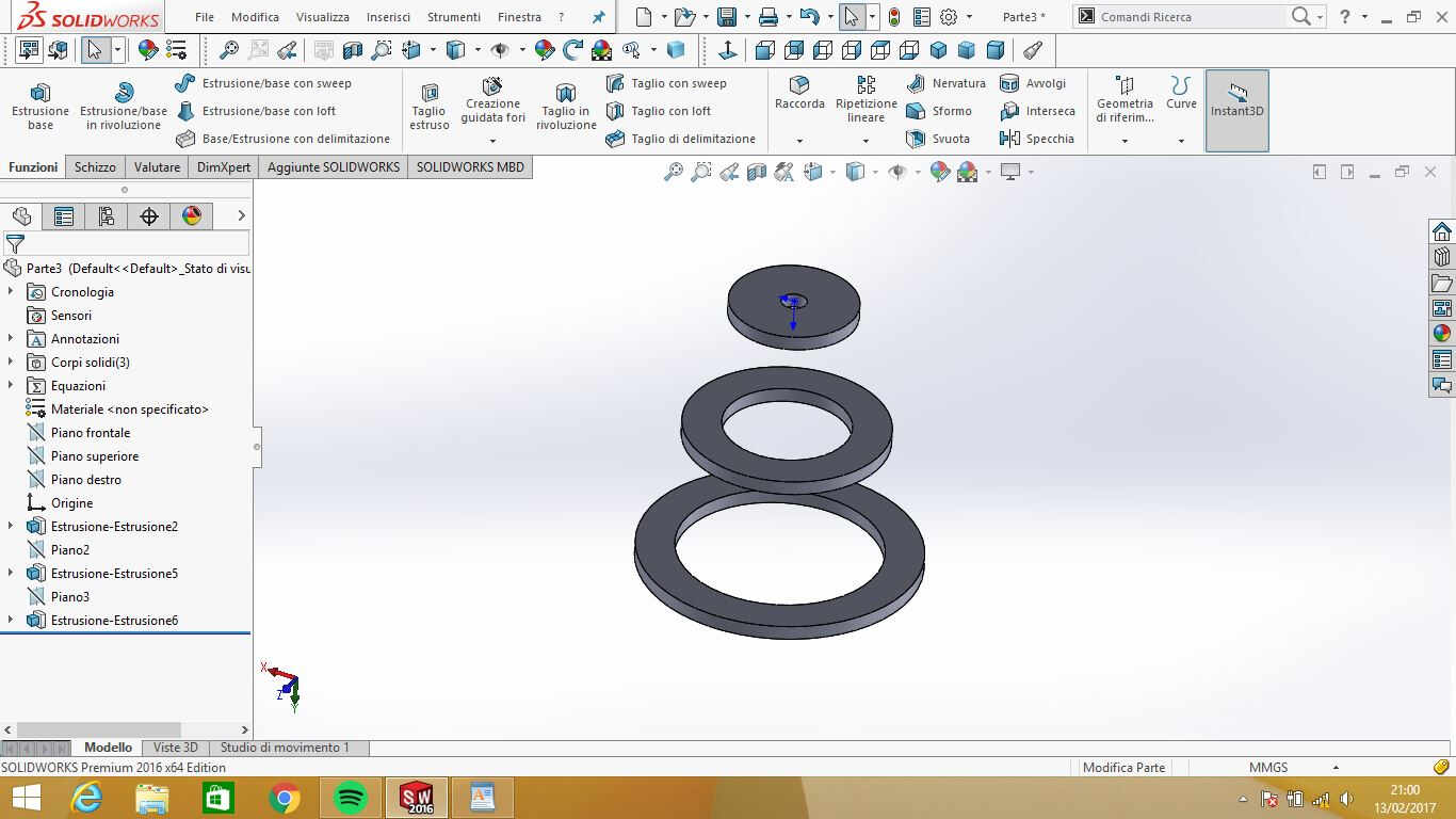 NB: extrusion height is equal to material thickness.
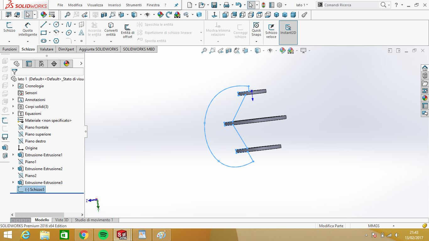
I then chose the plane that split in half the three solid bodies and opened a new sketch on it:
NB: extrusion height is equal to material thickness.
I then chose the plane that split in half the three solid bodies and opened a new sketch on it:
 NB: to do that is important to put the circle center on origin.
I draw a free curve without parameters making sure that lines of future joint were corresponding.
 I couldn't manage to make it parametric only by hiding circles extrusions and give a quote to sides so I extruded the new sketch and exported it as a .dxf file.
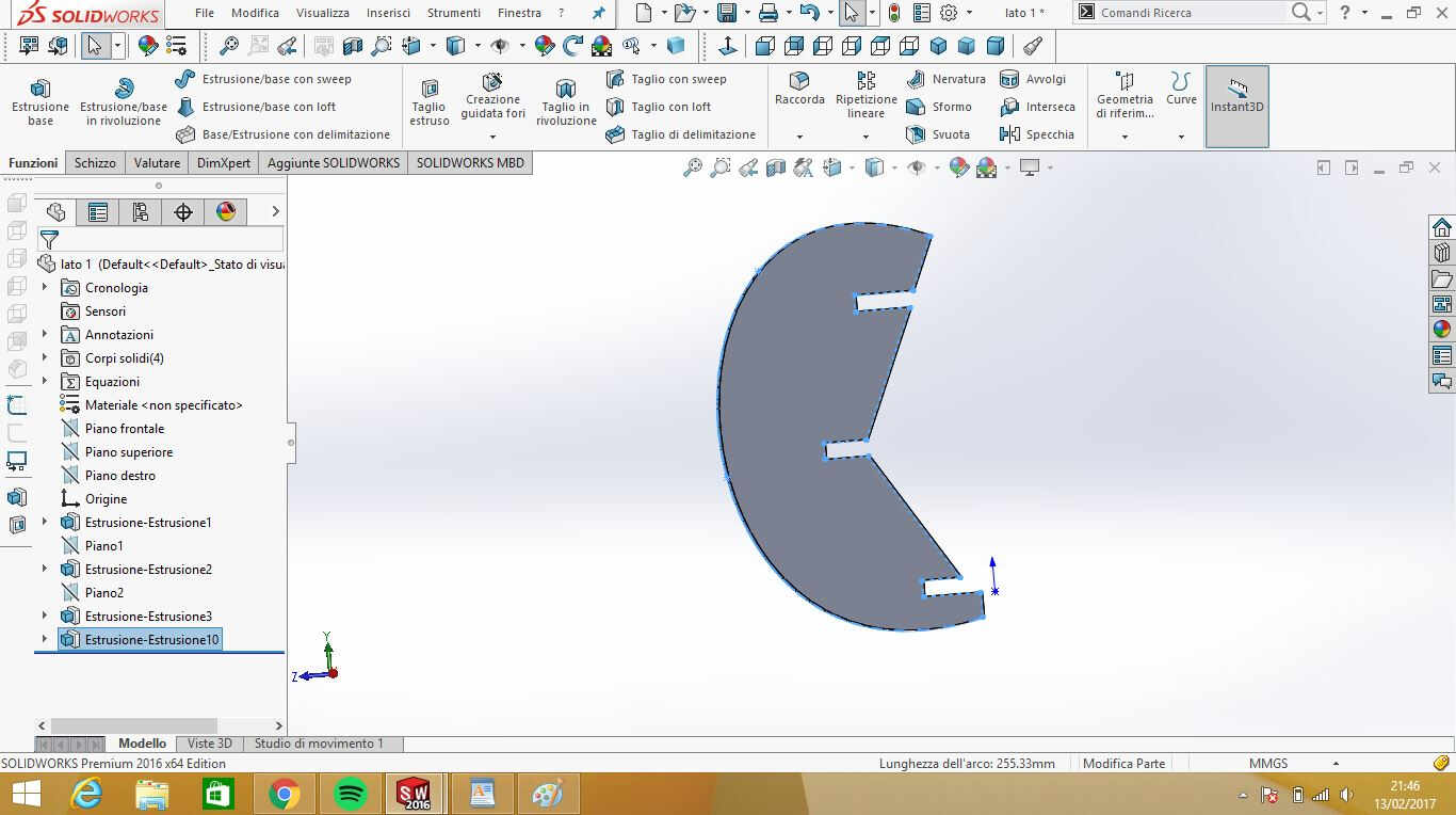 Now I could open it in a new part ( File-->Open... and choose .dxf where format is asked) and add parameters:
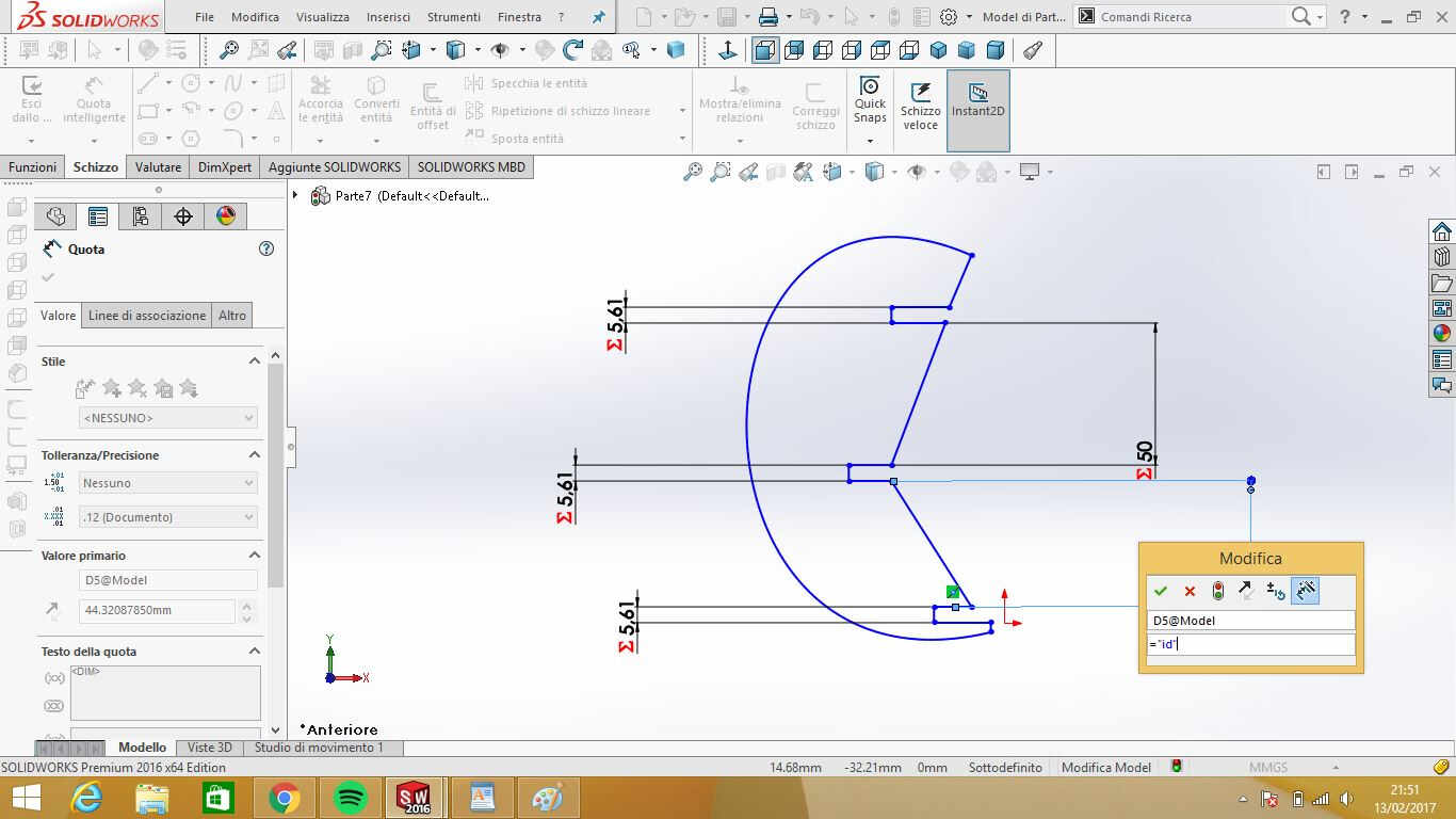 Once variables were added I extruded it again to have .dxf file to be cut.
I followed the same procedure in sketching the second shape (that suited different circles order):
As you can see in the pictures above, I didn't use material thickness as variable for joint of
female component but I subtracted double of kerf value. If you're asking yourself why,
I will try to give you an explanation but during this week so many theories arose among my fablab walls
that I come to the conclusion that, due to the fact that everyone of us managed to get to a result with
his/her own opinion about how kerf should be used, due also to all those irritably different kerf values
we found, to lack of calipers precision and to my past experiences with laser cutting,
KERF IS JUST DISCRETIONALY RANDOM VARIABLE.
So basically, we may say that
it doesn't exist. But let's say I'm wrong with this last opinion and assume kerf has a defined, unique
value for all plywood panel we used (even if humidity made them boat-shaped and impossible to be cut with
same settings along all width and lenght).
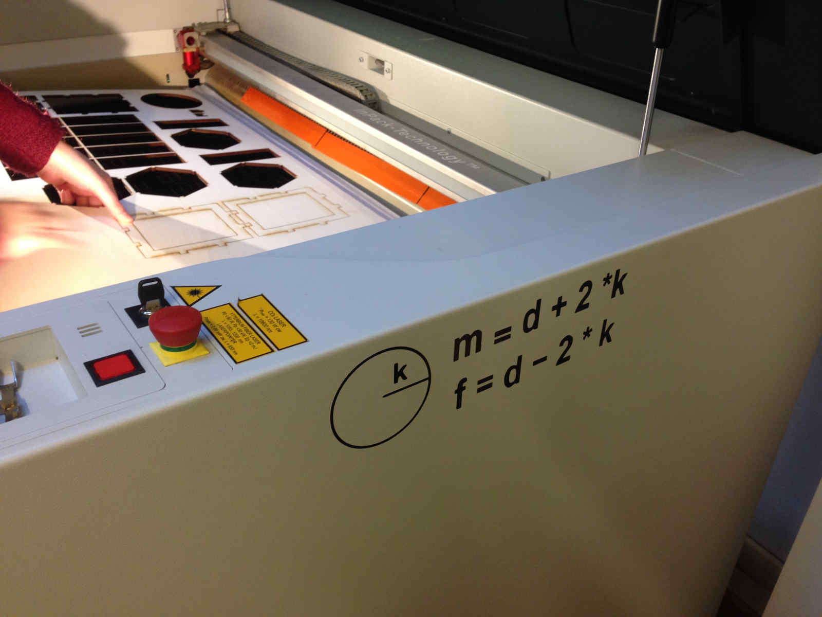
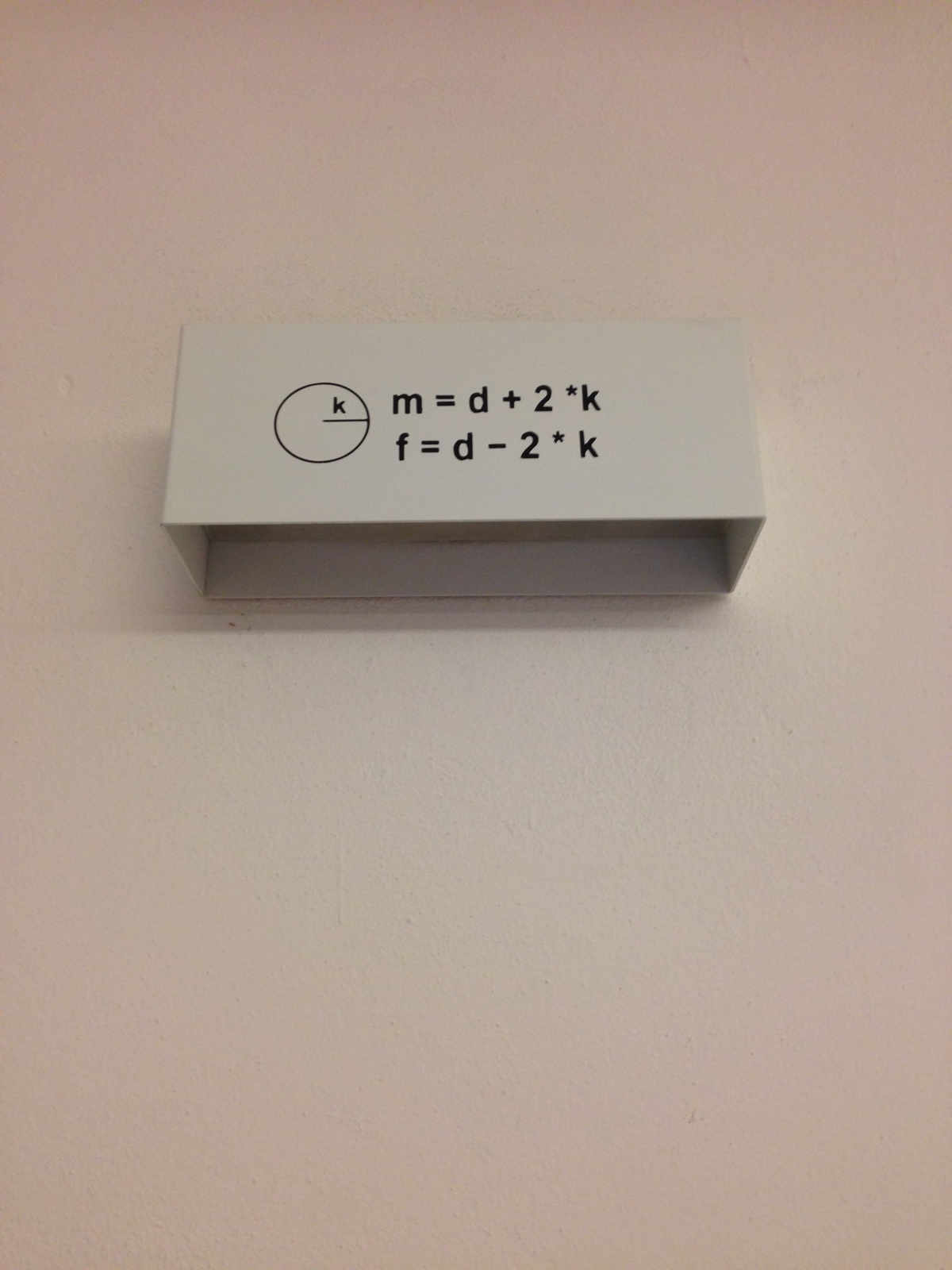
...But what does kerf really represents? As our instructor explained us, it corresponds
to laser light beam radius. So, each time we cut something, 2*kerf value material is burnt
and taken away from cut pieces. Therefore we have to consider that in joint sketches.
The rule I come out with was that in drawing male components I had to add twice kerf to
desired length, while I have to take the same quantity away to female components dimensions.
Since I easily made mistakes in calculating this relation every time, I helped myself like this:
 We found best cutting settings to be 40% speed and 80W power with 0.045 mm kerf during our test.
So I used this kerf value in Solidworks equations. Anyway, once I sent my .dxf file to laser cutter
(as explained above) I found put that coverings (female components in my case) were too tiny to fit with circles.
We found best cutting settings to be 40% speed and 80W power with 0.045 mm kerf during our test.
So I used this kerf value in Solidworks equations. Anyway, once I sent my .dxf file to laser cutter
(as explained above) I found put that coverings (female components in my case) were too tiny to fit with circles.
I immediately understood there was something around kerf and in fact, in the end anyone of us found
different kerf value for his/her panel with same speed and power. That's the biggest point I have to
solve about this week but, since deadline was approaching, I empirically changed values of interest on
Illustrator to find the exact dimensions for my joint (and I also changed a covering shape to look nicer)
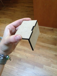
because I wanted to have a prototype of my project idea:
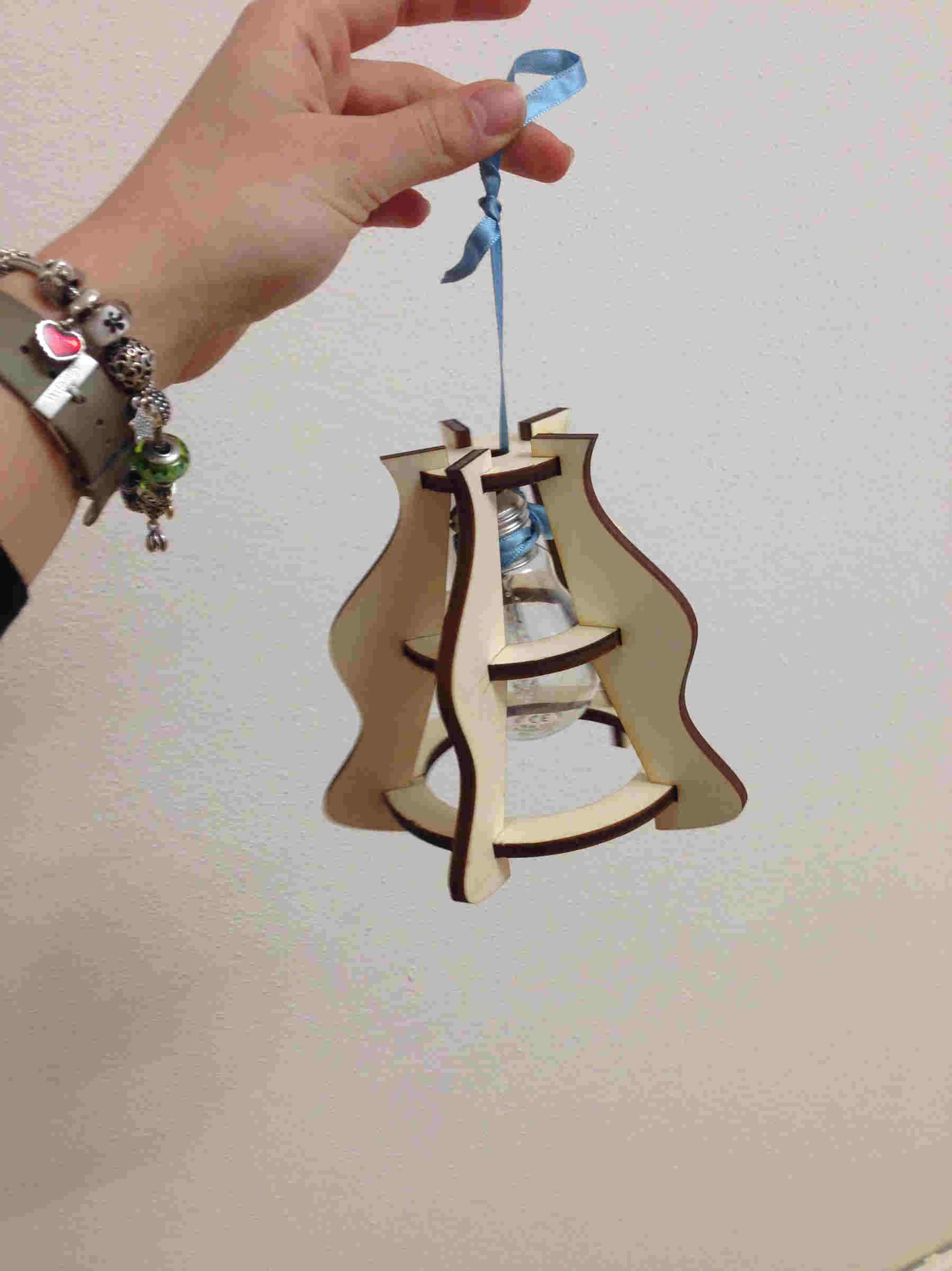
.jpg)
Conclusions
In conclusion, what I intend to do to sort out this week assignment in the next future is to:
- find a better method to calculate kerf, with the least uncertainty of result;
- re-test conformity between sketch perfect joint and laser-cut one;
- improve my lamp socket design with more circles and to set parameters also in external curve of covering shapes
Download
You can find my: