What we had to do this week was to create an ISP to be used to program all
the boards we will develop during next months.
We could choose among several already-made examples listed at the end of weekly
schedule page, then we just had to use provided files to replicate one and, only
after checking board worked properly, program it.
Ali's FabOptimus: getting files to mill PCB
The board I wanted to make was
Ali's FabISP because of those tons of complete documentation and tutorials his page provided me of.
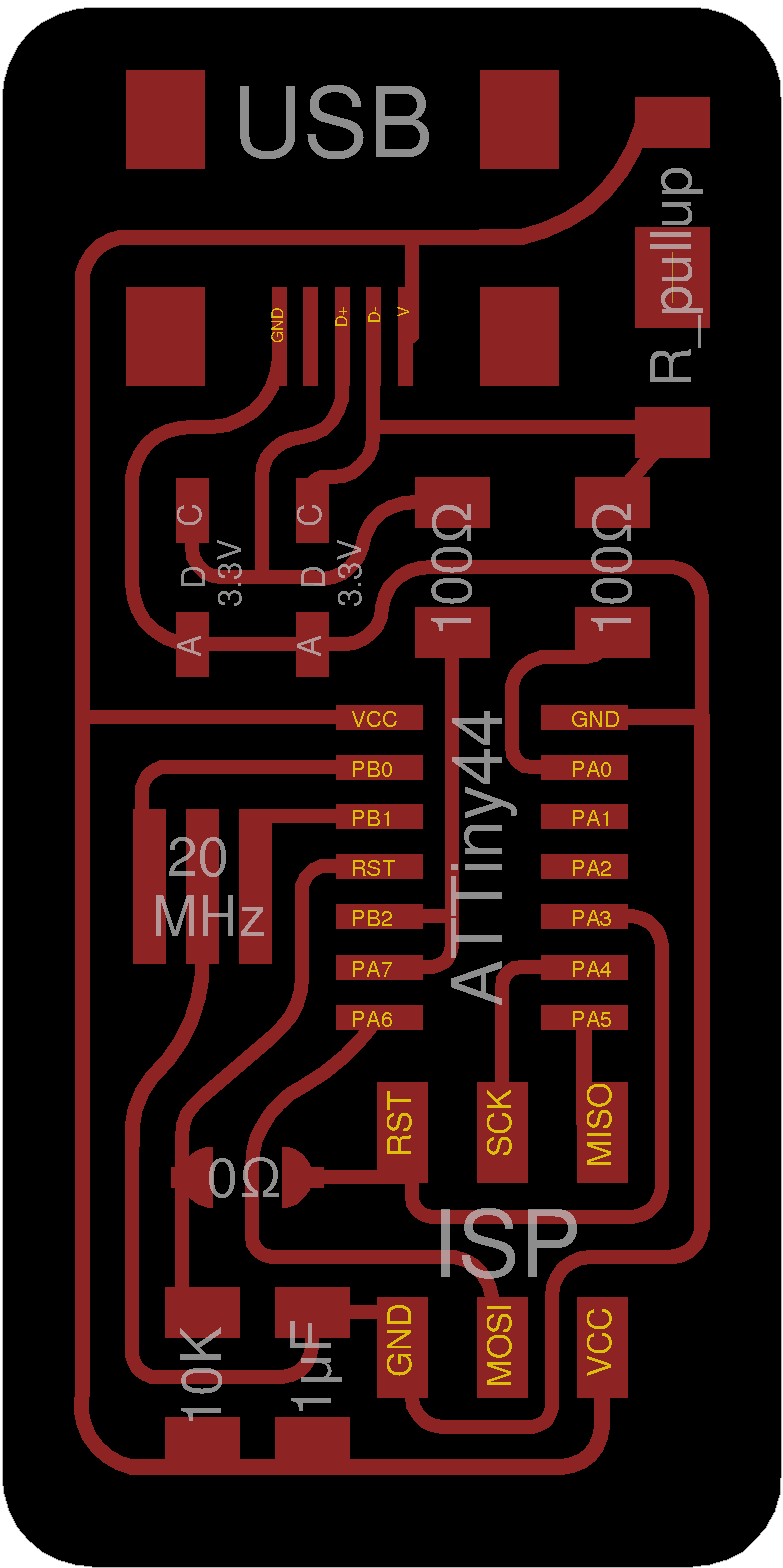
Basically, what I did was to download .png files of the ISP so as to use them
in fabmodules and mill the PCB with my FabLab's
monoFab SRM-20.
Below the files (board ouline and traces) I looked for:
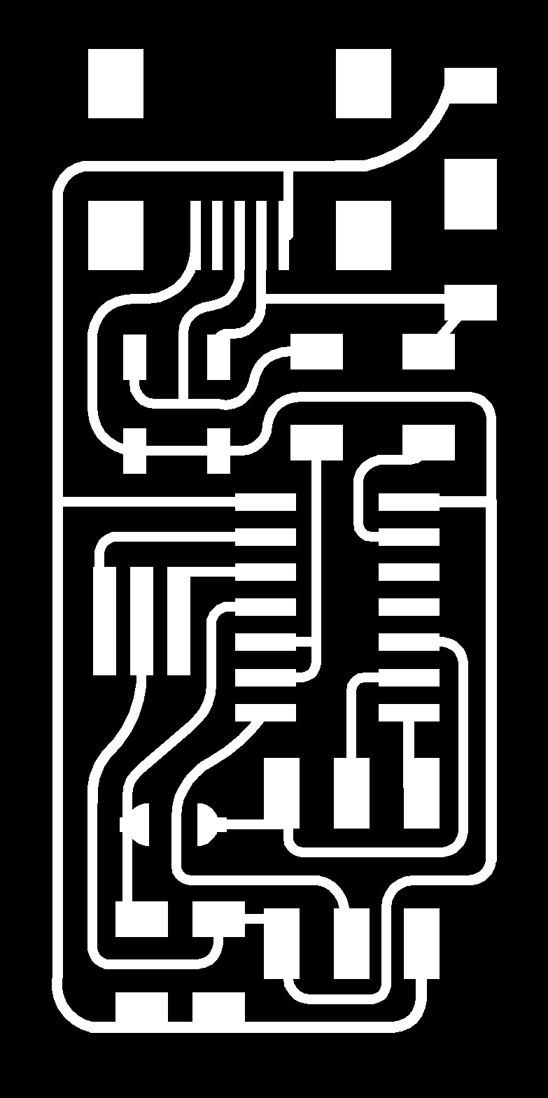

NB: remember that monoFab SRM-20 engraves what in black and leaves what in white, so reverse image color if needed.
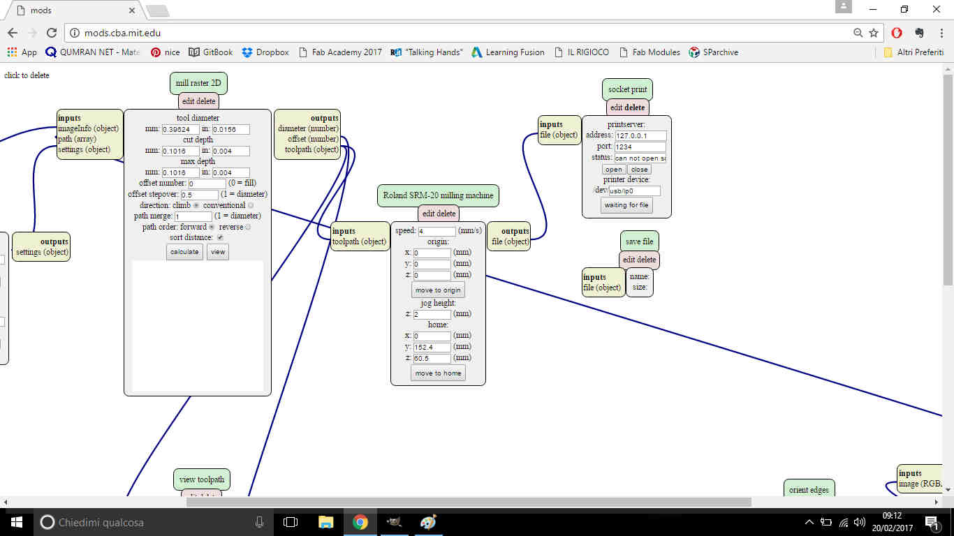
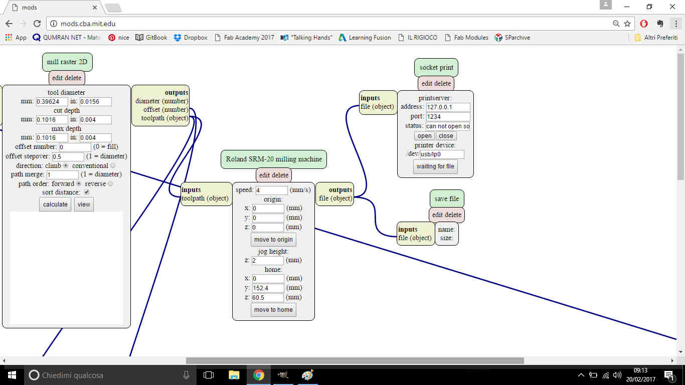
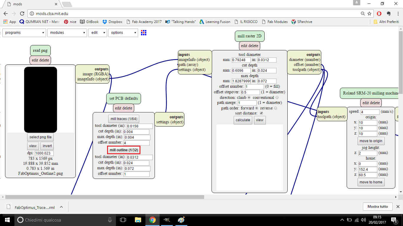
I then opened new fabmodules and told
them what I wanted to do going through Program-->Open server program--> Machines->Roland->mill->SRM-20
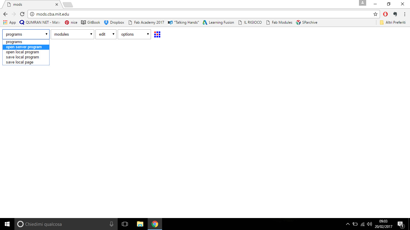
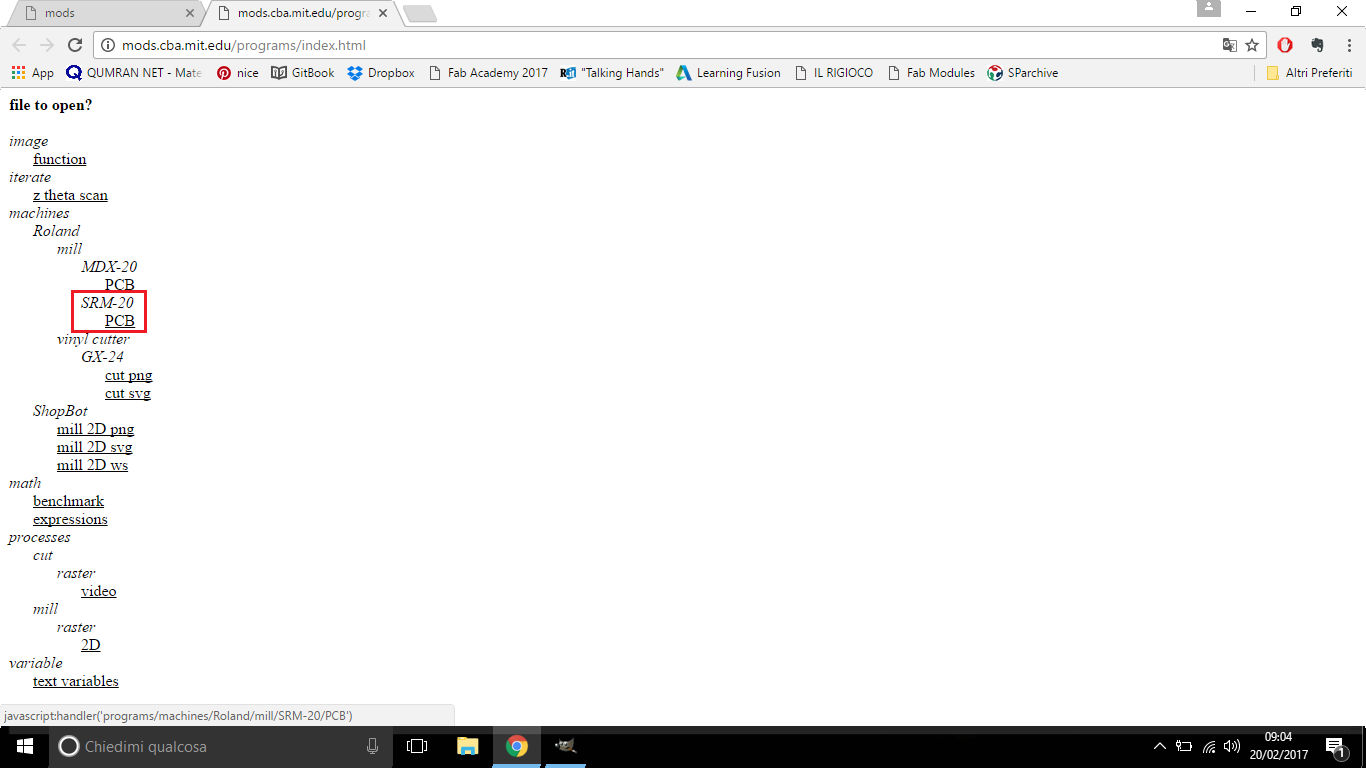
...and program settings windows appeared:
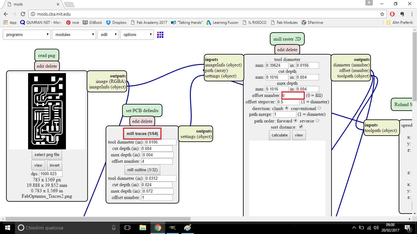
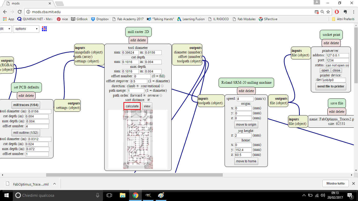
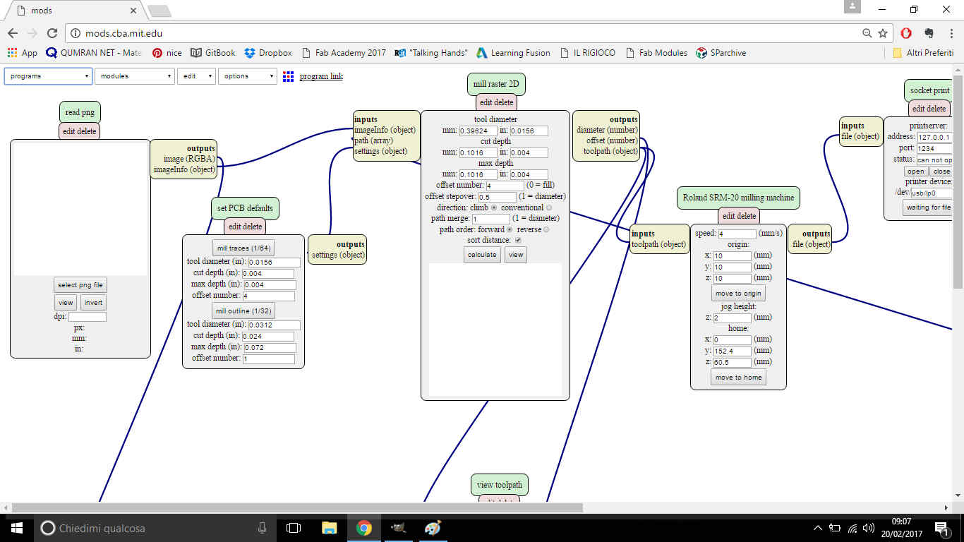 So I loaded traces .png file and changed some settings:
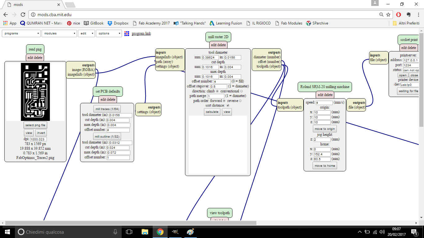
- Choose mill traces (1/64) in set PCB defaults panel;
- Set 0 value in offset number voice inside mill raster 2D panel;
- Set 0 value in origin X, Y, Z voice inside Roland SRM-20 milling machine panel;
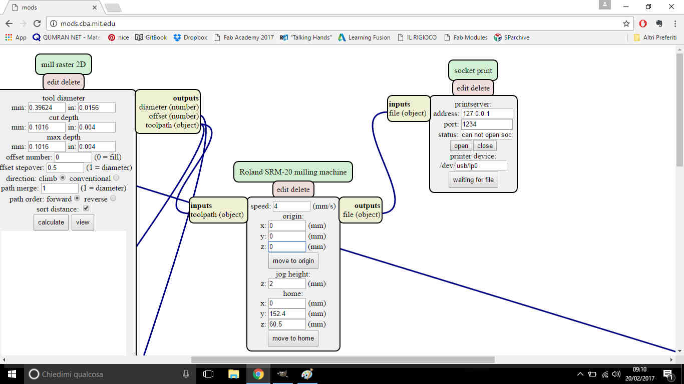
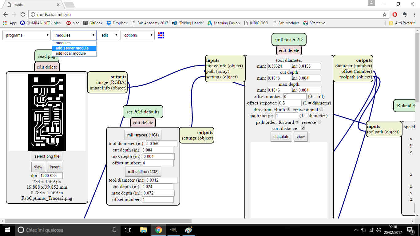
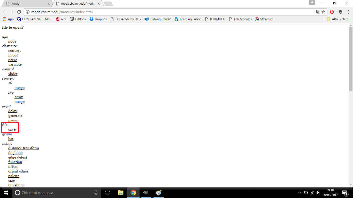
- Added Save module to workspace going through Module-->Add server module-->file->save and linked it in the right position;
After these steps, if you click on Calculate in mill raster 2D
panel, it should automatically show machine-suitable output and download it as a .rml file.
For what regards outline .png, all the steps above are the same except for set PCB defaults values:
in fact you have to choose 1/32 of inch tip and you can leave 1 as offset number value:
Thanks to Nicola Giannelli for fabmodules procedures and value setting support.
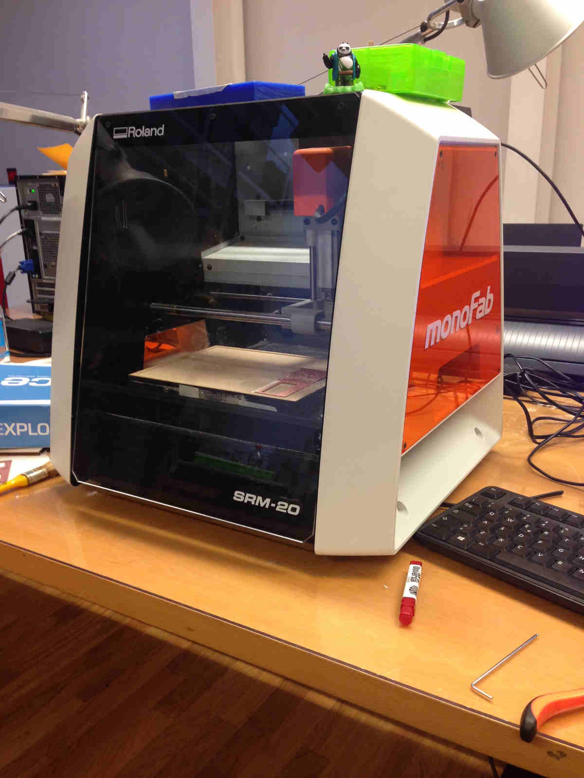
Milling with Roland's monoFab SRM-20
At this point you should have two .rml files: one for traces and one for outline milling.
This is my lab's Roland SRM-20:
Before sending them to the machine, it's important to set properly milling area. Make sure you have:
- FR-4 sheet;
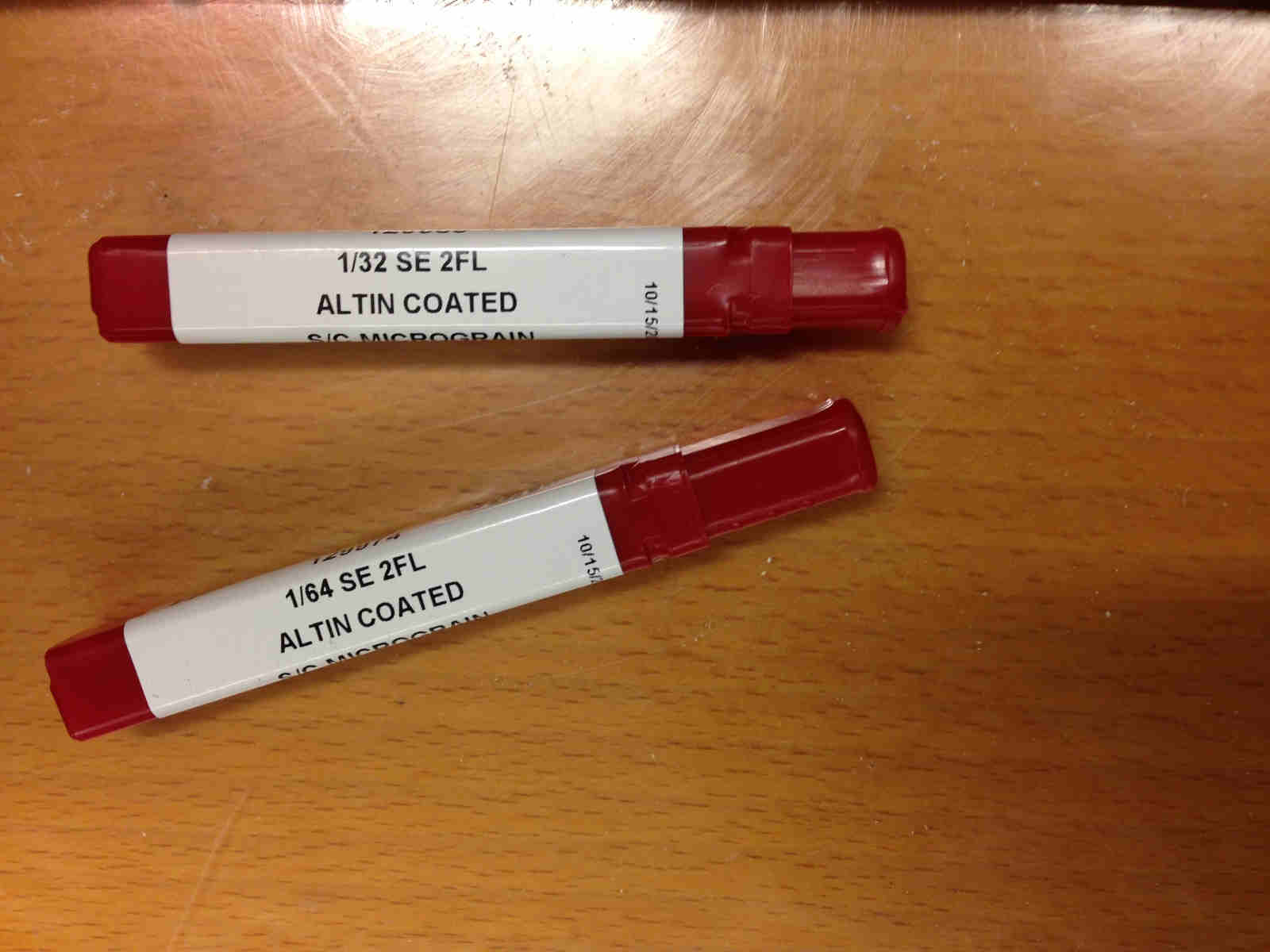
- 1/64 of inch tip (for traces engraving);
- 1/32 of inch tip (for edge cutting);
- double-sided tape
Tips:
 Put double-sided tape in copper sheet rear and stick it firmly to work plate.
Then set 1/64 tip - first you engrave traces outer space, then you cut PCB edges. To do that you need
a specific key to unscrew tip header and remove previously set tip -if there's one-, put the one you need inside
and screw clockwise to block it.
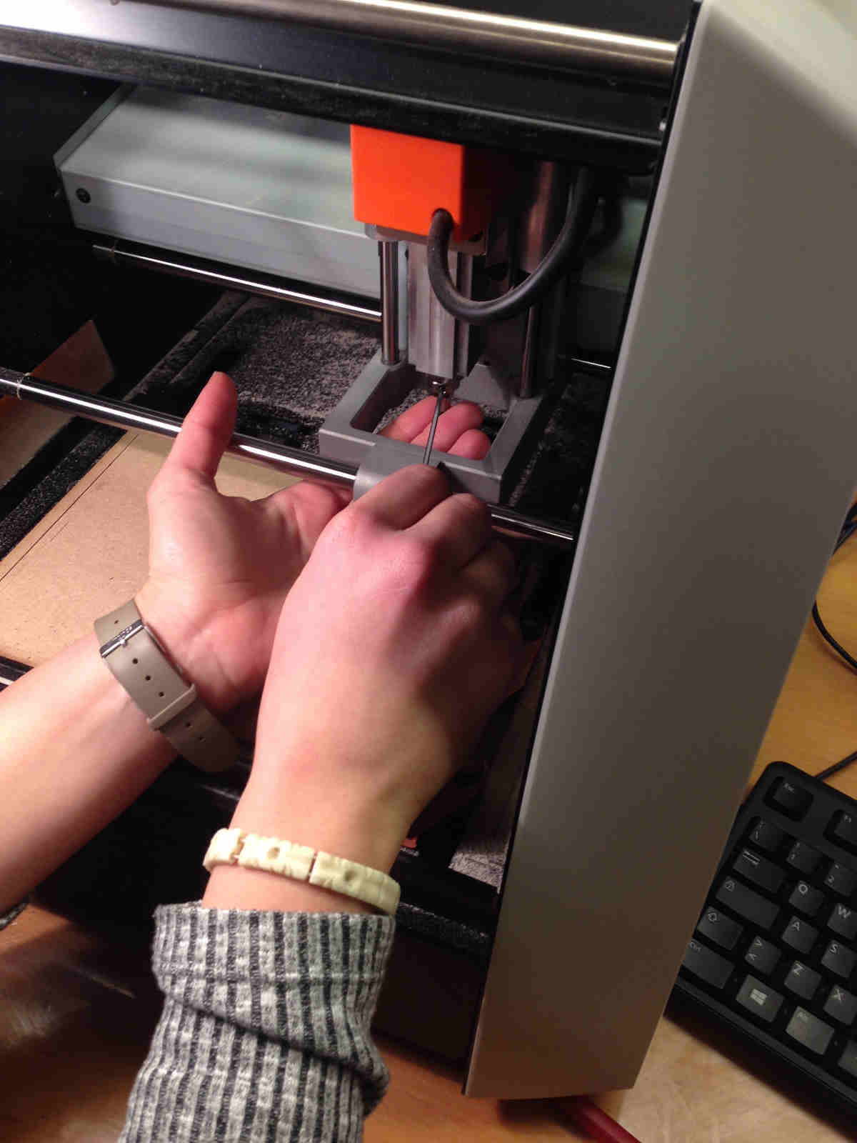
NB: always put your fingers under the tip when you unscrew so as not to let it fall ruinously.
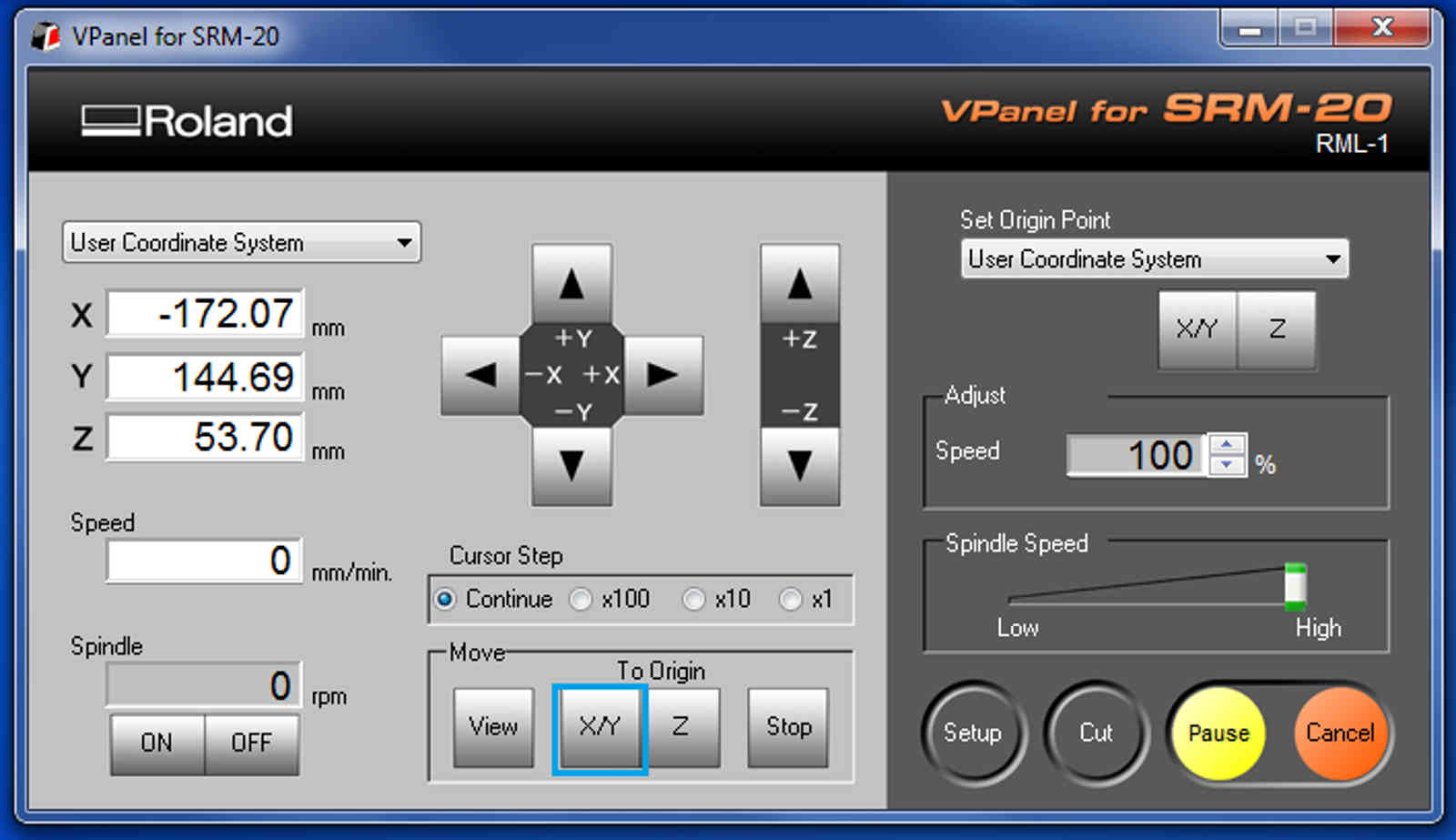
Now, you can open monoFab's software:VPanel for SRM-20.
First step is to set the origin: its position should be in the bottom left of your workspace.
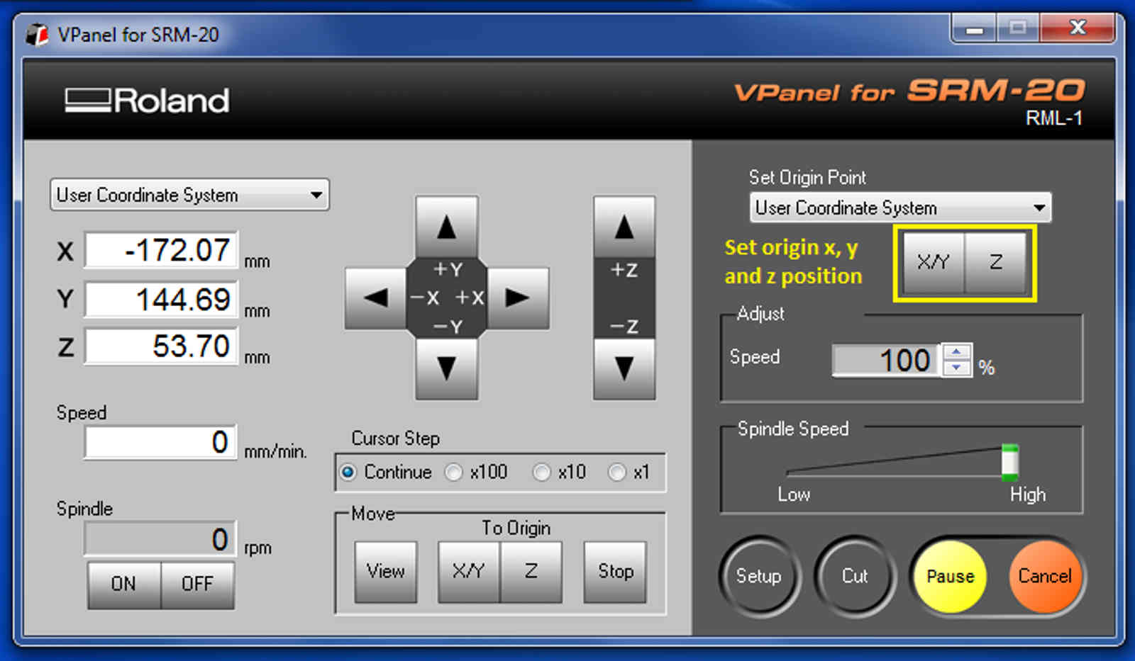
To set X,Y and Z you have to use these buttons:
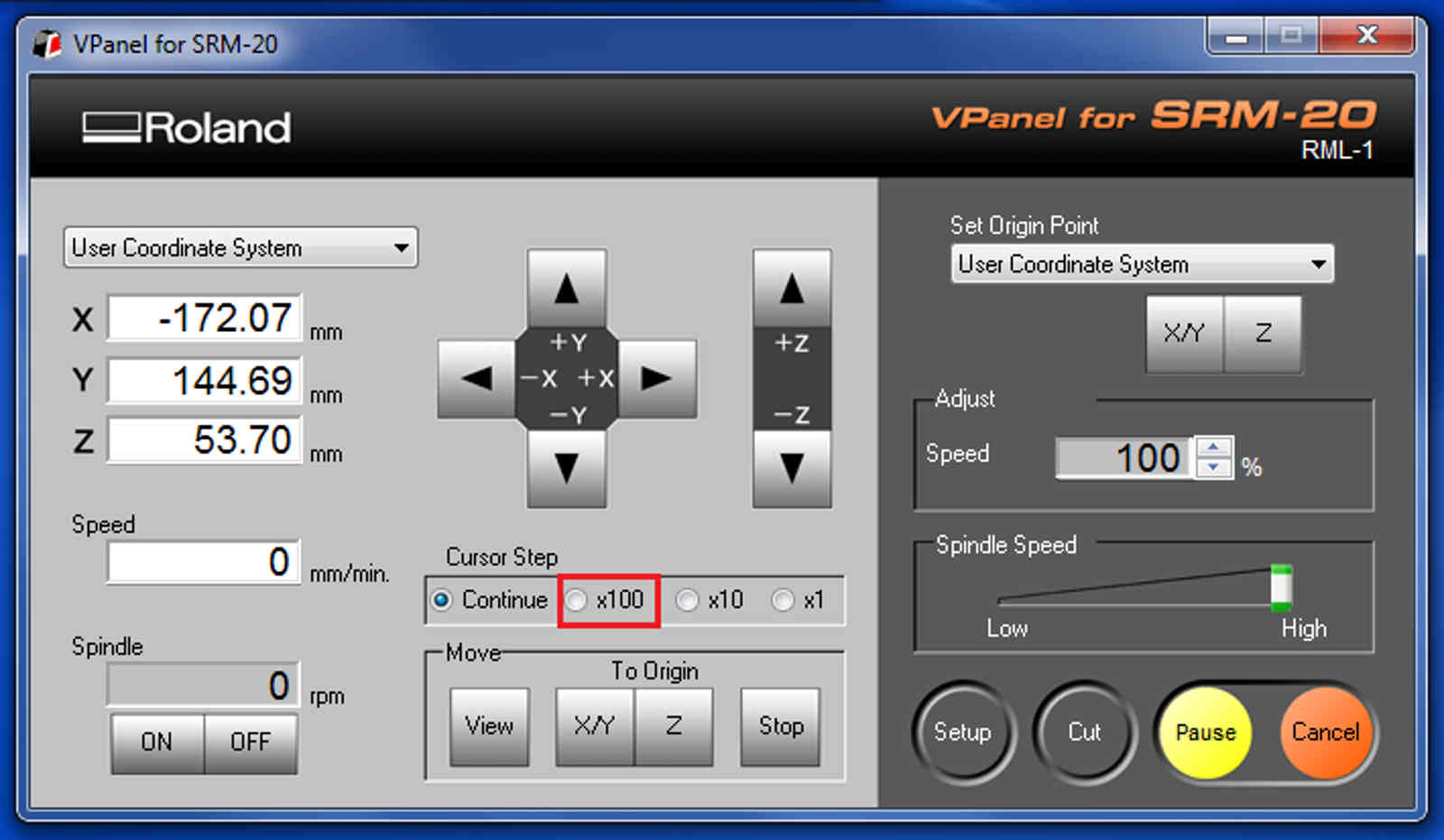
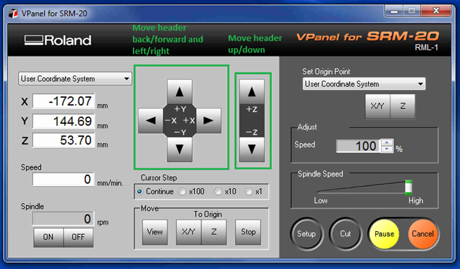 IMPORTANT: setting Z position is what you have to pay more attention to! The far end of the tip
is really tiny and delicate so it can easily broke. Therefore it's recommended to change header speed from
Continue to 100x
IMPORTANT: setting Z position is what you have to pay more attention to! The far end of the tip
is really tiny and delicate so it can easily broke. Therefore it's recommended to change header speed from
Continue to 100x
 To avoid damages, you should:
- lower header until 3-4 mm between header and copper are left;
- unscrew the tip till it gently touches the plate;
- screw clockwise while holding it with your fingers.
NB: hold firmly the tip so as not to let it be pulled by header while screwing.
Once you positioned X,Y and Z as you want, tell the machine that point is the origin:
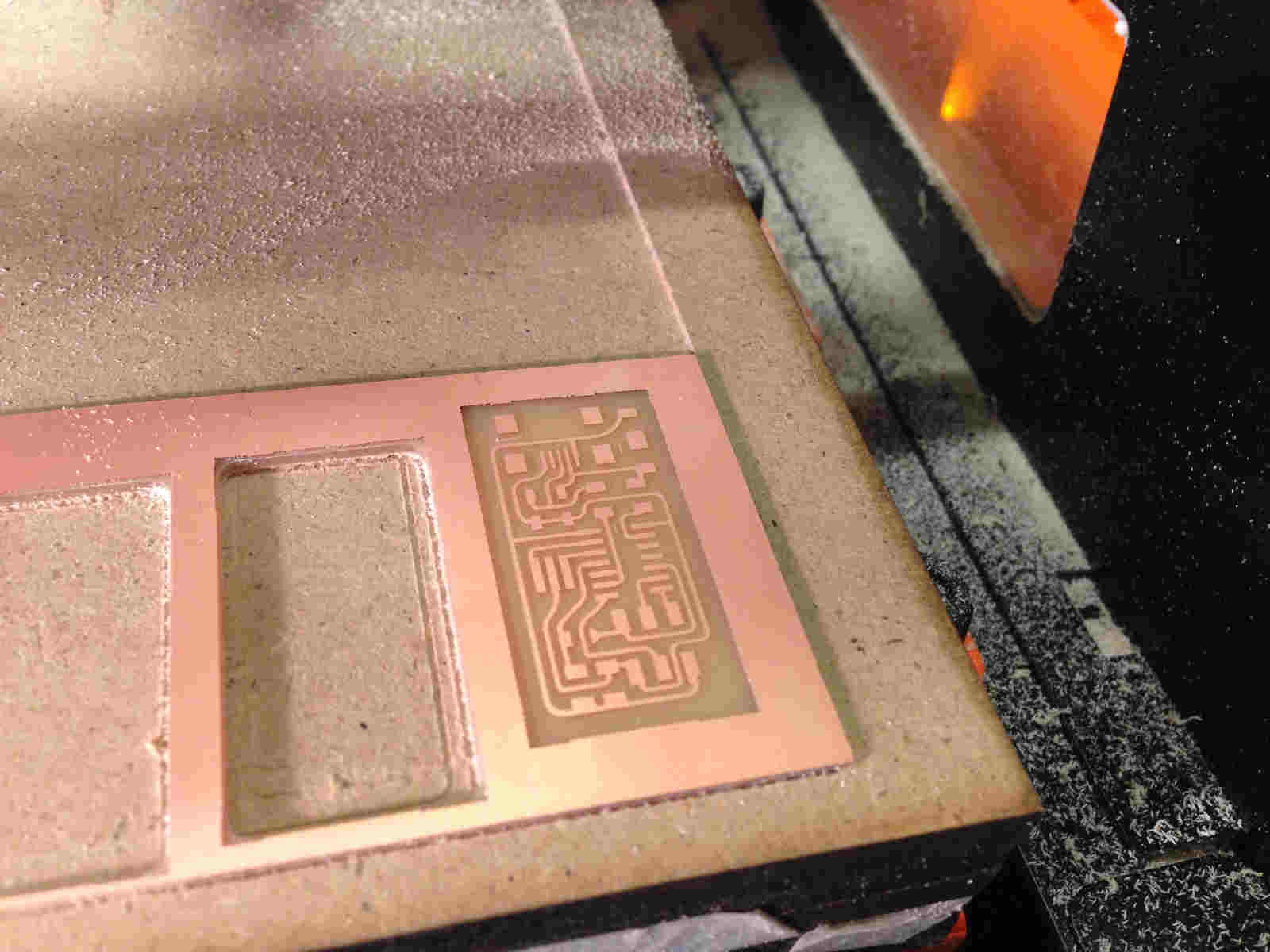
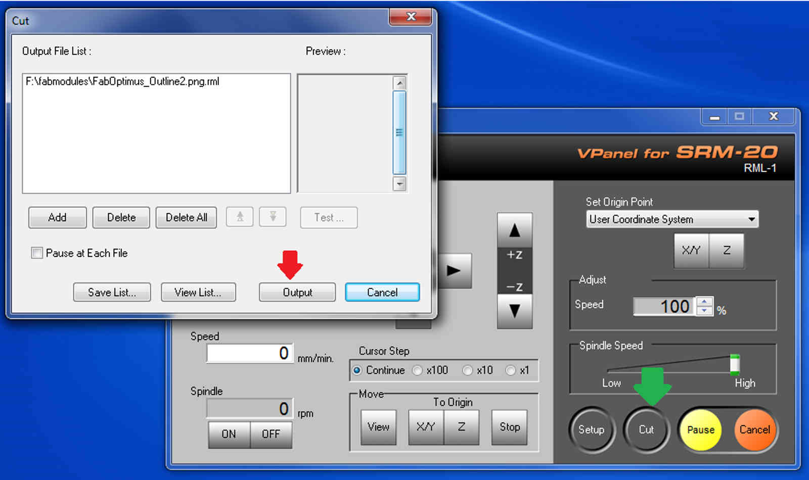
Now it's time to mill traces: click on Cut button and add traces .rml file, then just run your work.
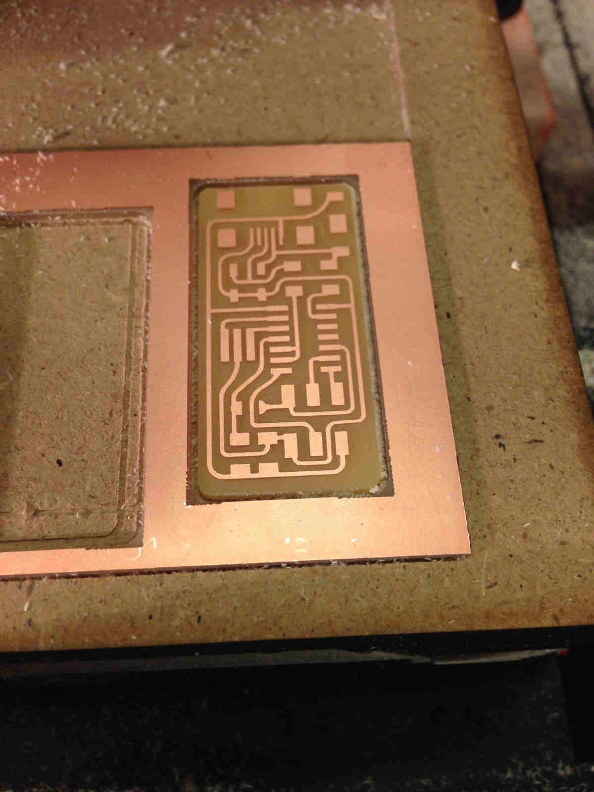
NB: first you engrave traces then you cut the outline!
The result should look like this:
 You now have to cut PCB edges. To do that you have to to change tip from 1/64 to 1/32
(follow steps above to set new Z to origin).
You now have to cut PCB edges. To do that you have to to change tip from 1/64 to 1/32
(follow steps above to set new Z to origin).
NB: origin's X and Y HAVE TO be the same as before, so just move the header
to position using button below and then set the new Z.
 Run outline cutting pressing Cut button, deleting previous works and adding outline .rml file:
Final result should be like this:
 IMPORTANT: before soldering, wash PCB with water and soap and dry it.
I know it can seem a dangerous action but I found out there's no damage, rather it helps to remove that grease that coul oxidize your board.
IMPORTANT: before soldering, wash PCB with water and soap and dry it.
I know it can seem a dangerous action but I found out there's no damage, rather it helps to remove that grease that coul oxidize your board.
Soldering: a tricky way to face with "big hands" problem
I've always know my hands to be a little over common dimensions but I've always seen that as
an advantage in slapping people. Thus, for the first time in my life I felt them like an hindrance:
electonic components dimensions are in (2-4)mm range!
Anyway, I had to find a way to fill my PCB with proper elements and I wrote my BOM (bill of material) looking on
FabOptimus documentation.
.jpg)
I then set my working area making sure I had:
- double-side tape to stick PCB to the table;
- soldering iron;
- solder;
- lamp with magnifying glass;
- pincers;
- desoldering wire
Spares of soldering wire home-made reel:
.jpg)
I decided to start from inner components and I always had schematic image at my fingertips to check
where I had to put what. But actually I think soldering best method doesn't exist, everyone
has his/her preferences in workflow setting.
TO NOTICE:
- soldering iron works at 340°C, so if you go too close with your face (because you're blind like me) you might get burnt - don't judge me please;
- pay attention not to keep soldering iron tip too longer into damp sponge cause it could melt and stick to soldering tip;
- when resistors try to rear up like a wild horse, they actually are saying you should have fixed other component far end before;
- ISP is an easy but bulky component so it's best to solder it at the end;
- even if soldering looks smooth and shiny, it's always better to double check that they work properly with multimeter.
- while soldering, maybe it will help you to keep board image on your notebook in front of your working area (below, mine)
- 1- some pin squared areas aren't fully covered by solder;
- 2- some solder shapes are too spheric;
- 3- some components aren't properly aligned with traces;
- 1- I didn't put enough solder on squared areas;
- 2- I didn't heat up traces properly before adding solder ( perfect shape shoul be like a wave from component to trace);
- 3- I didn't find an adequate compromise with the fact that I had just two hands to keep soldering iron, solder and pincers.
.jpg)
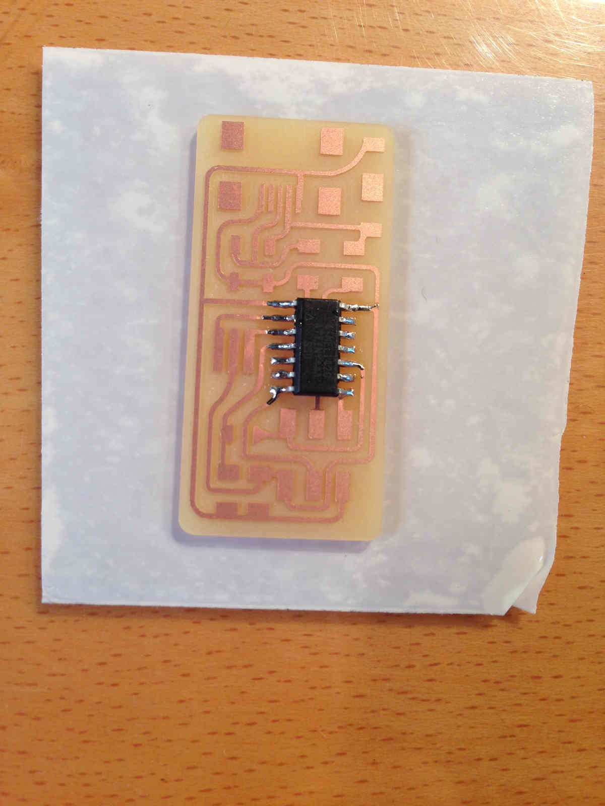
.....tadaaaaaaaaaaaaaaaaaaaaaaaaaaaaan! :)
That's my first result!
.jpg)
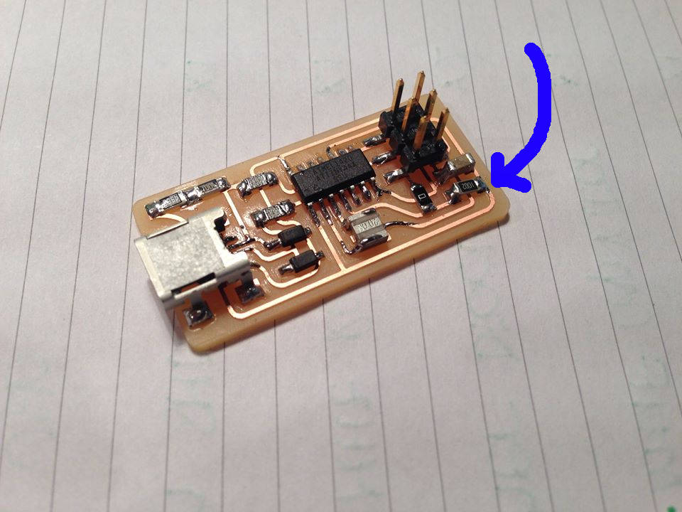 NB: please notice my skittish resistor.
Those of you that are more skilled in soldering can see that my ISP presents some ERRORS:
What should I blame that to?
ISP programming
Actually programming the ISP was to me the easiest part ( also because
Simone Guercio)
followed me step by step explaining what I was telling to the terminal while writing commands listed in
this tutorial.
I suggest you to take time and read the guide because it clearly explain what to do.
I will summarize the process brommercial programmer but in steps below you can find
how to make it known to your computer editing downloaded file.
ATTENTION: ISP and programmer have to be linked ad shown above, to say it easily,
when you link them with SPI cable their mini-usb port have to be in the same direction.
Steps to follow:
- 1-Get AVR programming software(AVRDUDE1) needed packages.
Commands:
sudo apt-get install flex byacc bison gcc libusb-dev avrdude
sudo apt-get install gcc-avr
sudo apt-get install avr-libc
sudo apt-get install libc6-dev
during steps above you may be asked to install also additional packages, answer yes every time.
- 2-Download the firmware from the Fab Academy Electronics Production page.
Commands:
cd ~/Desktop
wget http://academy.cba.mit.edu/classes/embedded_programming/firmware.zip
unzip firmware.zip
- 3-Edit Makefile2 if you're not using ATAVRISP2 programmer.
Commands:
nano Makefile
A text editor window will open containing the Makefile. Go to the line that says:
#AVRDUDE = avrdude -c usbtiny -p $(DEVICE) # edit this line for your programmer

AVRDUDE = avrdude -c avrisp2 -P usb -p $(DEVICE) # edit this line for your programmer
Then, if using the USBtiny programmer or another FabISP- Remove the "#" in front of the line with "usbtiny" in it;
- Add a "#" to beginning the line with the "avrisp2" in it to comment it out;
- save the Makefile
- 4-Program your ISP.
Commands:
Open firmware folder if you're not already inside:cd Desktop/firmware
Then type
make clean3
answer should be:
yourComputer@name~/Desktop/firmware$ make clean

rm -f main.hex main.lst main.obj main.cof main.list main.map main.eep.hex

main.elf *.o usbdrv/*.o main.s usbdrv/oddebug.s usbdrv/usbdrv.s
type
make hex4
answer should be:
yourComputer@name:~/Desktop/firmware$ make hex

avr-gcc -Wall -Os -DF_CPU=20000000	 -Iusbdrv -I. -DDEBUG_LEVEL=0

-mmcu=attiny44 -c usbdrv/usbdrv.c -o usbdrv/usbdrv.o

avr-gcc -Wall -Os -DF_CPU=20000000	 -Iusbdrv -I. -DDEBUG_LEVEL=0

-mmcu=attiny44 -x assembler-with-cpp -c usbdrv/usbdrvasm.S -o usbdrv/usbdrvasm.o

avr-gcc -Wall -Os -DF_CPU=20000000	 -Iusbdrv -I. -DDEBUG_LEVEL=0

-mmcu=attiny44 -c usbdrv/oddebug.c -o usbdrv/oddebug.o

avr-gcc -Wall -Os -DF_CPU=20000000	 -Iusbdrv -I. -DDEBUG_LEVEL=0

-mmcu=attiny44 -c main.c -o main.o

avr-gcc -Wall -Os -DF_CPU=20000000	 -Iusbdrv -I. -DDEBUG_LEVEL=0

-mmcu=attiny44 -o main.elf usbdrv/usbdrv.o usbdrv/usbdrvasm.o usbdrv/oddebug.o

main.o

rm -f main.hex main.eep.hex

avr-objcopy -j .text -j .data -O ihex main.elf main.hex

avr-size main.hex

   text	   data	    bss	    dec	    hex	filename

      0	   2020	      0	   2020	    7e4	main.h
type
make fuse5
If the answer ends with
avrdude: safemode: Fuses OK


avrdude done.  Thank you.
your ISP has been programmed successfully.
What was done in this step was just to switch from AVRISP2 to USBTINY -that inclues any on FabISP- programmer.
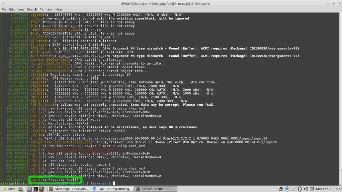
Programming should has work but to double check your ISP works properly, you have to connect it directly
via USB to your pc and type lsusb to verify your computer correctly sees it:
to definitely feel like Ben Stiller in Zoolander you have to check shell answers you with something like
Bus 002 Device 004: ID 1781:0c9f Multiple Vendors.
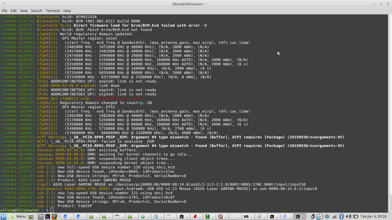
If you're trustless (like me) type dmesg and finally feel proud if you see your ISP among devices listed.
 After you hymn of joy, go back to soldering station and remove 0 ohm jumper to prevent your ISP from being programmed again.
NOTES
1:AVRDUDE is the most popular software uploader to send code to flash programmer.
It works with a quite large variety of programmer. If you want to make sure you installed it, tipe avrdude
in shell and if it shows all the command-line flags and arguemnt you're allowed to use, you did it,
otherwise check if the problem come from missing installation or computer's inability to find its
correct path -that's usual problem for Windows OS rather than Mac or Linux OS-.
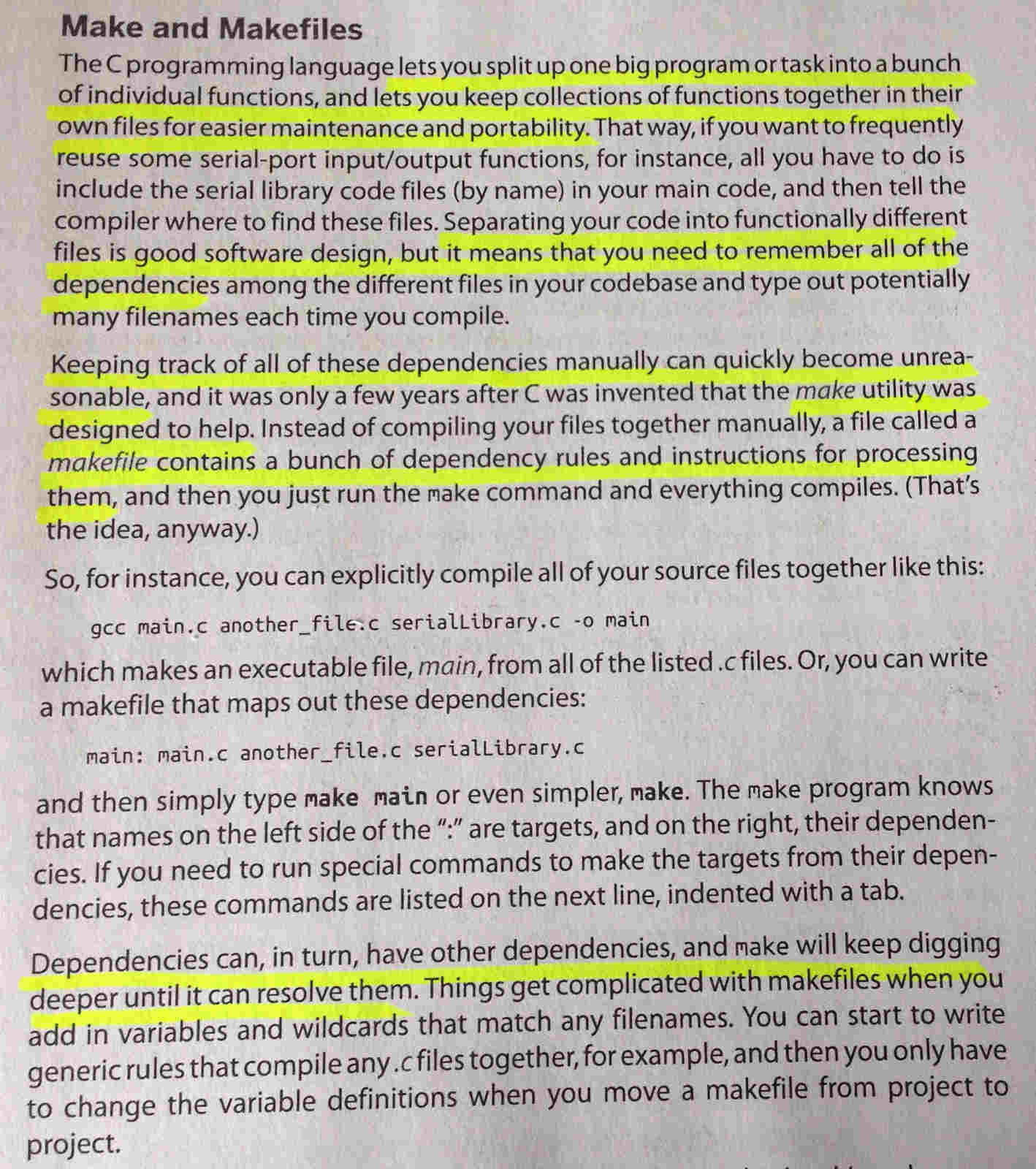
2: Makefile is an utility used in C programming that help keeping track of
dependencies while splitting a program into individual functions. Its convenience stays in that you can run several .c
files together only by typing make command and also that (if needed) you can edit just part (lines) of it
to run different programs instead of compiling a new one. Here
a simple tutorial on make command.
Below an explanation from ""Make:AVR Programming"" by Elliot Williams (Chapter 2, page 19):
3:
make clean command: to be discovered 4:
make hex command: to be discovered 5: fuses: I may say fuses relates to microcontroller's clock speed, but, since my idea of the topic has to get clearer and complete, I just report definitions I found till now ( in "Make:AVR Programming" by Elliot Williams - Chapter 9, page 189 and 191):
CODE EXPLANATION
See week 8.
Conclusions
I admit I was quite lucky to have a working programmer at my first attempt, but
the part I liked was that I had to rely just on my manual abilities to get to result.
I found soldering quite relaxing but at the same
time somehow challenging. I would have liked to do more, but I think I'll have several
opportunities to develop my soldering skills in next future.
Thus, on one side I'm not that satisfied
because I just did what tutorials said me to do without diving deeply in my actions' meaning. Therefore, owing to my lack
of google-fu I've started to read Make: AVR Programming by Elliot Williams to move my step forward in microcontroller
programming; first topics I would like to understand are commands I used to program my ISP.
Moreover, I want to fix some solderings on my ISP and test it again, if it still works properly I'm going
to brush some nail polish over my board so as to protect it.
Download
.rml files here
Update 6th June 2017
I realized I didn't prove my FabISP could program other boards itself. During past weeks I designed and developed many PCB and in order to aknowledge my FabISP functioning,
I tried to program another board.
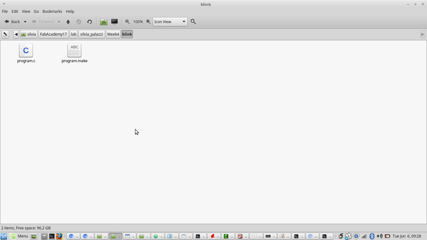
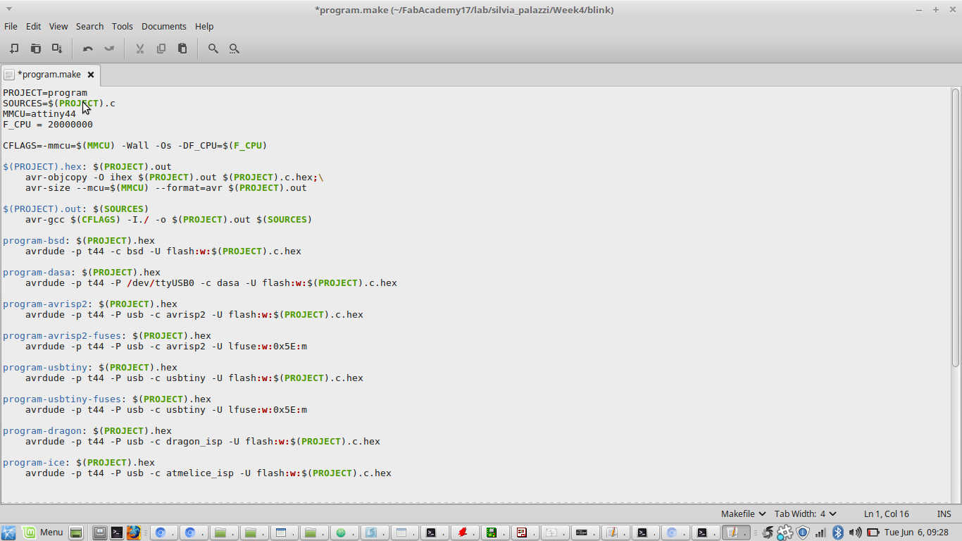
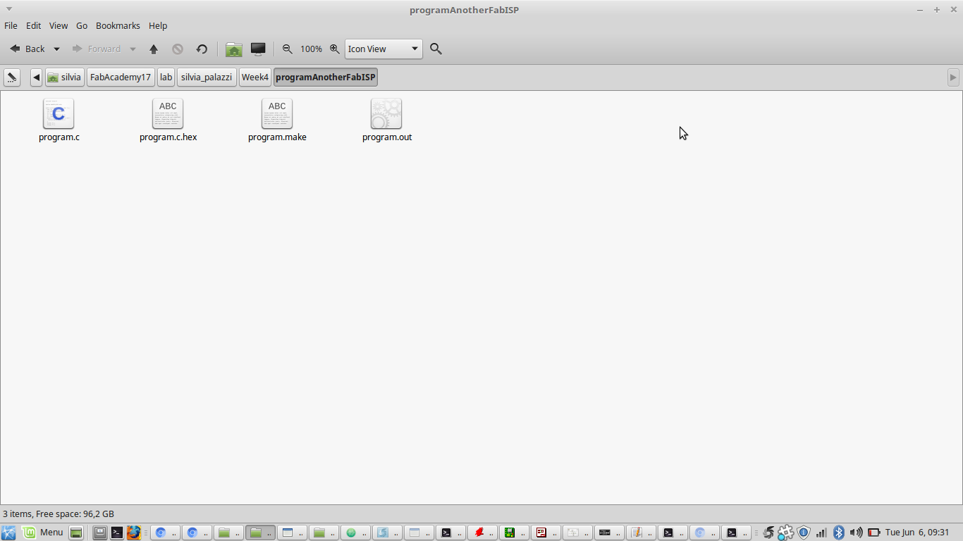
To do that, I created a folder with a make file and a C code (see week8 for more):
dmseg command:
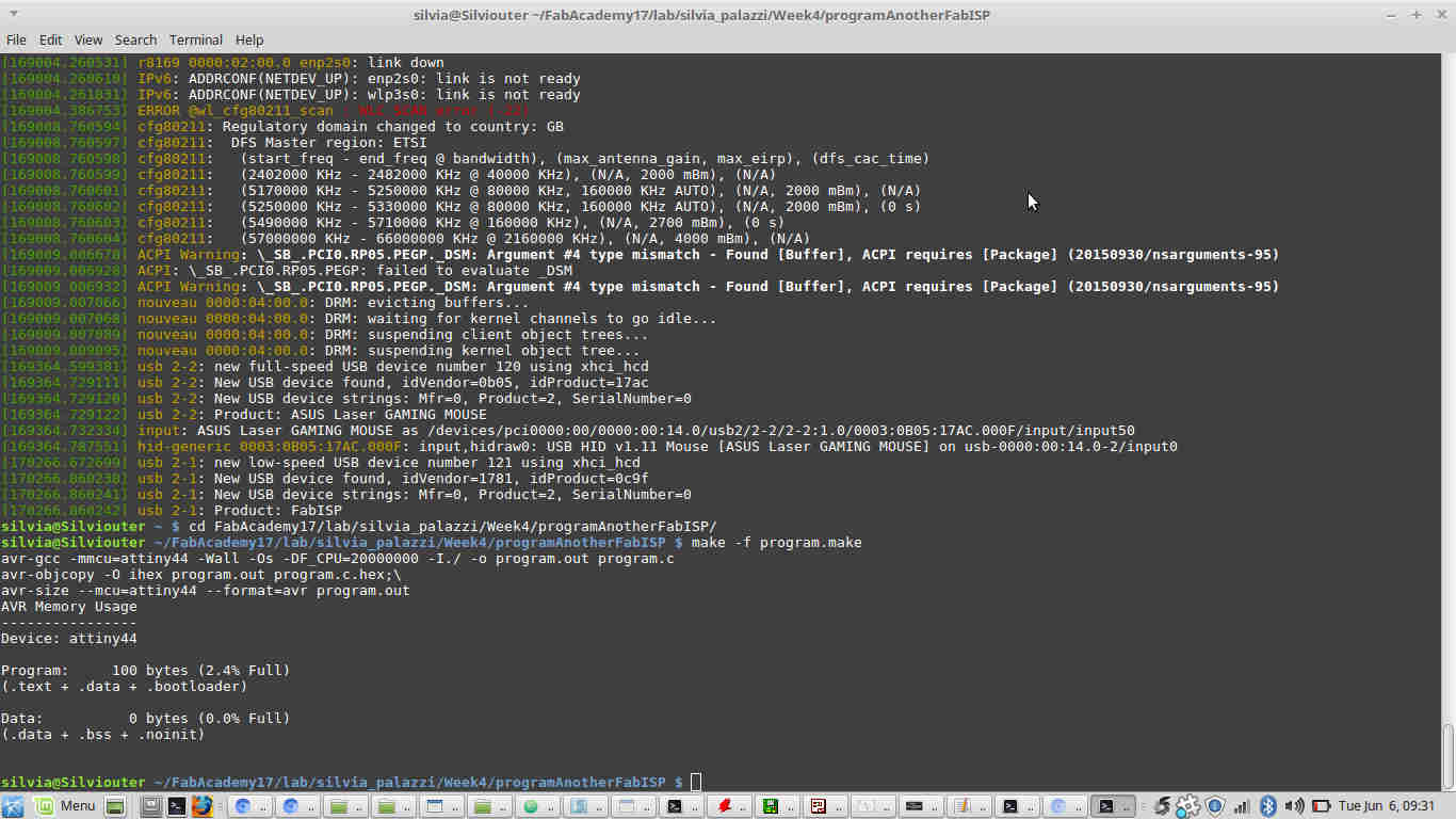
I so moved into the code folder and ran
make -f makefilename.make to create .hex and .out files:
make -f makefilename.make program-usbtiny I got this error:
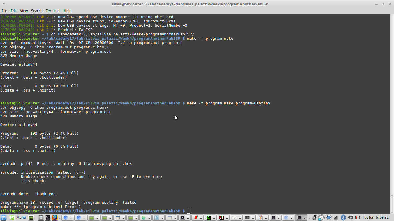
make -f makefilename.make program-usbtiny
command, once the board was rightly connected to the FabISP. Everything went fine this time: