Faults Confession
Ok, even before Fab Academy 2017 started, I knew this week arrival would have been like a Damocles' sword pending on
my head...And finally it fell on me.
I had never even tried to face with C, C++, Javascript, Python or other potential languages.
No occasion?? Mmmmmh
No helpful people to teach you? Mmmmmmh
...That's it...
I know a notebook didn't ever killev anyone, I know an #include had never swallowed up anybody, but I know I could die trying to crash my computer with my head and got trapped inside it after three-hour-debugging attemps after an #include mistake.
I tried to escape the schedule as long as I could (ERROR) just after little reading of-LPTHW: Learn Python the Hard Way
- it was not the author's fault (the book was really thorough as a starting point in getting to know coding world).
I tried to fill up
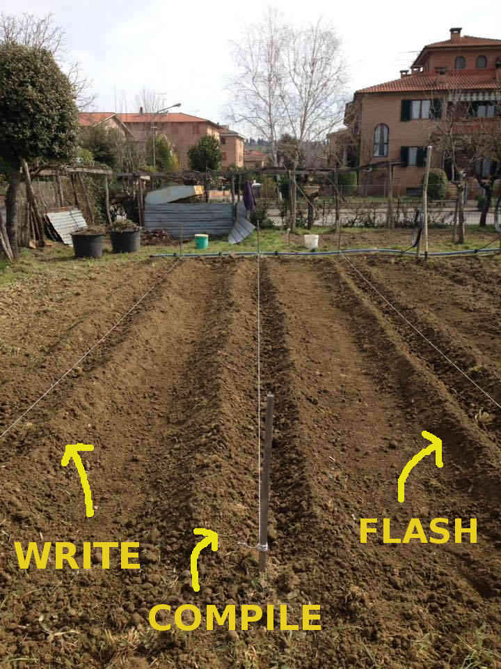
my time in any way....an example? Planting potatoes ;)

I can say I was Wasting Time the Hard Way...
 Do you know an harder way than hoeing the ground?!
....Anyway everything reminded my my duty:
Do you know an harder way than hoeing the ground?!
....Anyway everything reminded my my duty:
 -We will talk more about this toolchain later on-.
So, boots off and glasses on....SECOND ROUND!! DRIN DRIN DRIIIIN!
When it first get to non-educational programming in your life
I really lacked basics of microcontrollers and coding rules so I needed to study hard. I supplied myself with:
- Make:AVR Programming by Elliot WIlliams;
- LCTHW: Learn Code the Hard Way;
- LPTHW: Learn Python the Hard Way;
...for general knowledge
And with Attiny44 datasheet for specific info.
Now.....Let's start!
Make:AVR Programming..A theory full diving
Once I listened to my guardian angel, I opened Elliot Williams' tome
(451 pages) that I used almost like a dictionary so far and started reading Chapter 1, a complete (but not tedious)
exploration of AVR microcontrollers variety, structure and function.
I'll quickly list what I learnt:
- An AVR microcontroller is a very small computer with three types of memory:
- Flash memory: this is the non-volatile memory where your coding gets stored and that doesn't disappear when power goes off;
- RAM memory: volatile memory for temporary variables storage;
- EEPROM memory: slow-to-write-to and configuration settings memory that reamins after power goes off.
- The 8-bit CPU works is an electronic circuitry that conducts predefined logical and mathematical operations;
- To have a sense of time, microcontrollers are provided with internal clock which runs at different megaherz for different microcontrollers (CPU, RAM, ADC, Flash, EEPROM, I/O subsystem clock are divided down from internal clock)
- Pins have names and specific functions and they are organized into PORTS (something like 8-pins banks) that you can write to/read from;
- Ports are accessible via I/O registers;
- Programs are runned by reading pins values (1 high or 0 low);
- Internal ADCs and DCAs are necessary to link the microcontroller to other components that don't speak the same "language";
- Other important tools are interrupts tool and internal timers/counters
At the end of the chapter there's a nice overview of AVR microcontroller family:
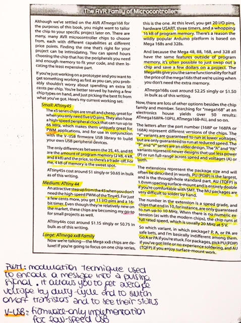
It looked simple, but just because I was fed with hardware definition. When I moved up to Chapter 2 things
got harder: it was programming time.
Toolchain definition clarified programming process a bit:
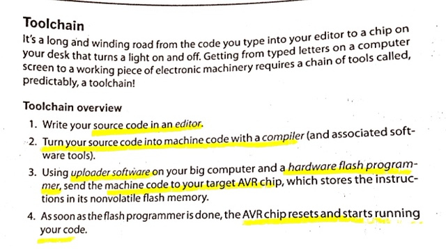 and also related info about software suggested narrowed the too large tool variety in this obscure new field.
Also, I learnt how pins configuration via registers worked.
HARDWARE REGISTERS
Almost all of AVR pins are configurable as input or output pins, that basically means they can behave like voltage sensing components or like transistor switches, connected to the VCC or GND voltage levels. Registers are easy-access (flash) memory locations (8 bit in case of Attiny44) that trace and report pin status. A register for all pins? No, each port has three registers:
- DDRx (data direction register- port x): this register check and decide if pin are set as inputo or output - by default, pin are set at 0 which defines input status;
- PORTx(port x data register): when DDRx is set to 1 (output), with PORTx register can set logic high or low (VCC or GND) for the pins considered, whereas if DDR set a pin like an input, with PORTx register you can activate internal pull-up that makes the input pin have fix values (=1), otherwise it would be really sensitive to oscillations and changes
- PINx(port x input pin address): they are where you read input pin values from (but you can also write in them)
Now, to understand how to use registers, let's just take the case in which you assign a value to a variable in your code:
What it happens at chip stage is that the compiler takes a free RAM slot, calls it "a" and set its value to 7. When you change variable's value, adding 1 to it i.e.,
it takes the value out from the slot, add 1 to it and puts it back.
For register it's almost the same process -taking "slots" as 8 pins banks- but, in addition to storing a value,
you also flip the switches that are linked to each of the 8 memory cells. So, each pin DDR memory locations are physically wired to two switches: when a 1
is stored in that pin, output switch is closed and input one is opened (OUTPUT STATUS), when a 0 is set, output switch is open
anad input one is closed (INPUT STATUS).
In conclusion, since default status for pins is input mode, to configure output pins you have to:
- Write in DDR those relevant pins for output mode;
- Give them a value (high or low) with PORT register.
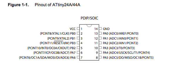
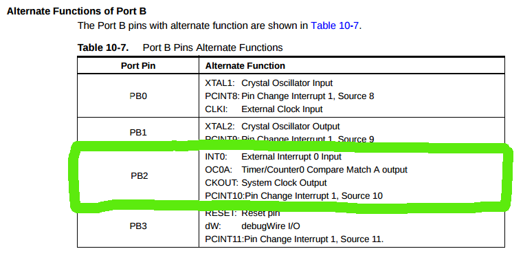
To practically see register and pins organization, on Attiny44 datasheet (page 67),
I found the image below and I clearly understood what I read before, since I had feedback in Attiny physical features:
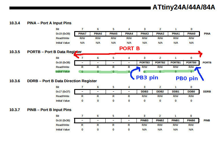
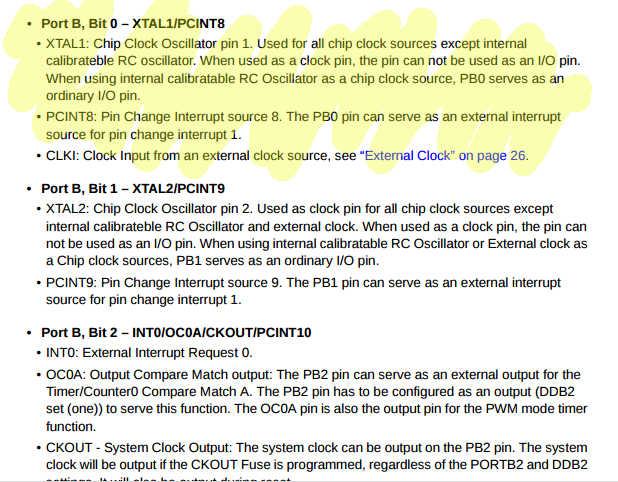
 And of each pin (PB0 i.e.) you can check function on datasheet:
For what regards writing a code I imagined I had misty belief about how-to simply because I missed general rules
but I had no idea about what compiling and flashing could mean.
I learnt that:
- COMPILING is turning a human-readable C code into machine language (10101011100011010010....);
- FLASHING means moving the code from computer to microcontroller.
COMPILING
To compile your code you need avr-gcc, AVR specific version of GCC compiler and a makefile,
a file that contains definition of various .c files dependencies and general info for the compiler.
I already faced with that file in
week6, but I gained greater
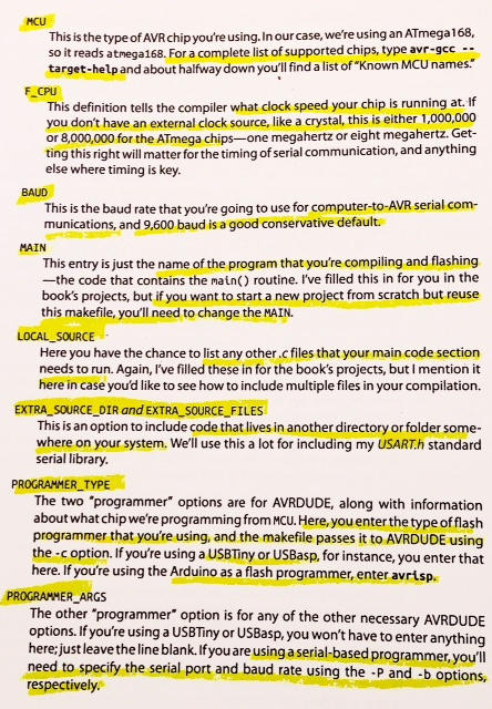
knowledge about configuration parameters with page 39 (Make:AVR Programming by Elliot Williams) explanation about
Blinking LEDs project makefile.
 Avr-lbc is the function library you can use in developing C file - you can
downlod it here.
Avr-lbc is the function library you can use in developing C file - you can
downlod it here.
Now you may be wondering about how to run this file: you simply type make in shell from your project folder and read
error description you receive back (because sure you do).
This command creates an .hex file from makefile which later has to be flashed with a programmer and AVRDUDE to the microcontroller.
FLASHING
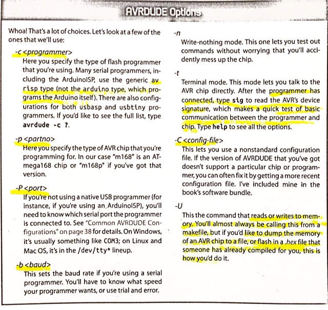
AVR-what??AVRDUDE is a programming software to talk
to and upload code onto your Atmel AVR microcontroller (you can find libraries and documentation
here). It supports more than 70 programmers and 100 chip types.
Nice...and what can I tell my Atmel microcontroller? You may narrate many fairy tales, but to surely have an answer it's best
to follow this guide:
 NB: remember to type
 sudo avrdude, because you're not allowed to do all operations if you're not super-user.
On page 36 and 37 (Make:AVR Programming by Elliot Williams) you also find nice debugging cases list.
Once you set values correctly in makefile and moved to project directory from shell, you're ready to load your code onto the microcontroller
with make flash command - this command runs .hex file created with make.
NB: if debugging takes a worring time, check AVRDUDE is correctly installed.
SERIAL COMMUNICATION
This all is so beautiful! But how do my notebook and my Attiny44 talk to each other? Well, as far as I understood it's
all about serial communication -explained in this nice article.
I was achieving practical knowledge about how to run .c files and makefiles but I missed the most important part: how can I write
a C file?
So I moved to C file structure.
What a simple C file looks like
I had started reading Learn Python the Hard Way and it gave me sense of code content since it clearly approaches to different
variables and function separately with loads of examples but I didn't wanted to be confused with definitions becuase I knew for C things
could be slightly different.
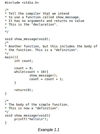
I so skipped to Chapter 4 of Learn Code the Hard Way to make myself an idea about
what C writing looked like and I found a nice example:
 I also found a specific tutorial about how to write a blinking led C file and a
complete book about C features that explained exhaustively the example below:
I also found a specific tutorial about how to write a blinking led C file and a
complete book about C features that explained exhaustively the example below:
 Briefly:
- #: this symbol introduces preprocessor1 directives
- < stdio.h > is an important library to be included when it comes to I/O pins manipulation
- main: this this where AVR starts executing code
- while: it indicates a cycle that repeatedly goes on as far as certain conditions are respected - to understand if conditions are respected or not, 0 value indicates false and 1 indicates true
- return (0): this instruction is required by OS to know whether they ran code correctly or not
- void: it has different roles if standing above or below code body.
- above: it declares function that will be used in the code and simply describes the type of the function and any arguments that it might take
- below: in this case void is used to make a declaration with the body of the function given too - in the example, the function show_message doesn't return a value so void is used
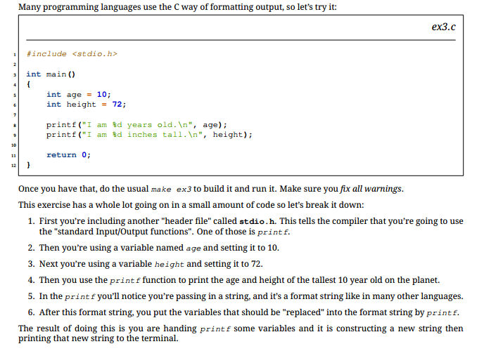
- printf: this function gives you back formatted text - read here.
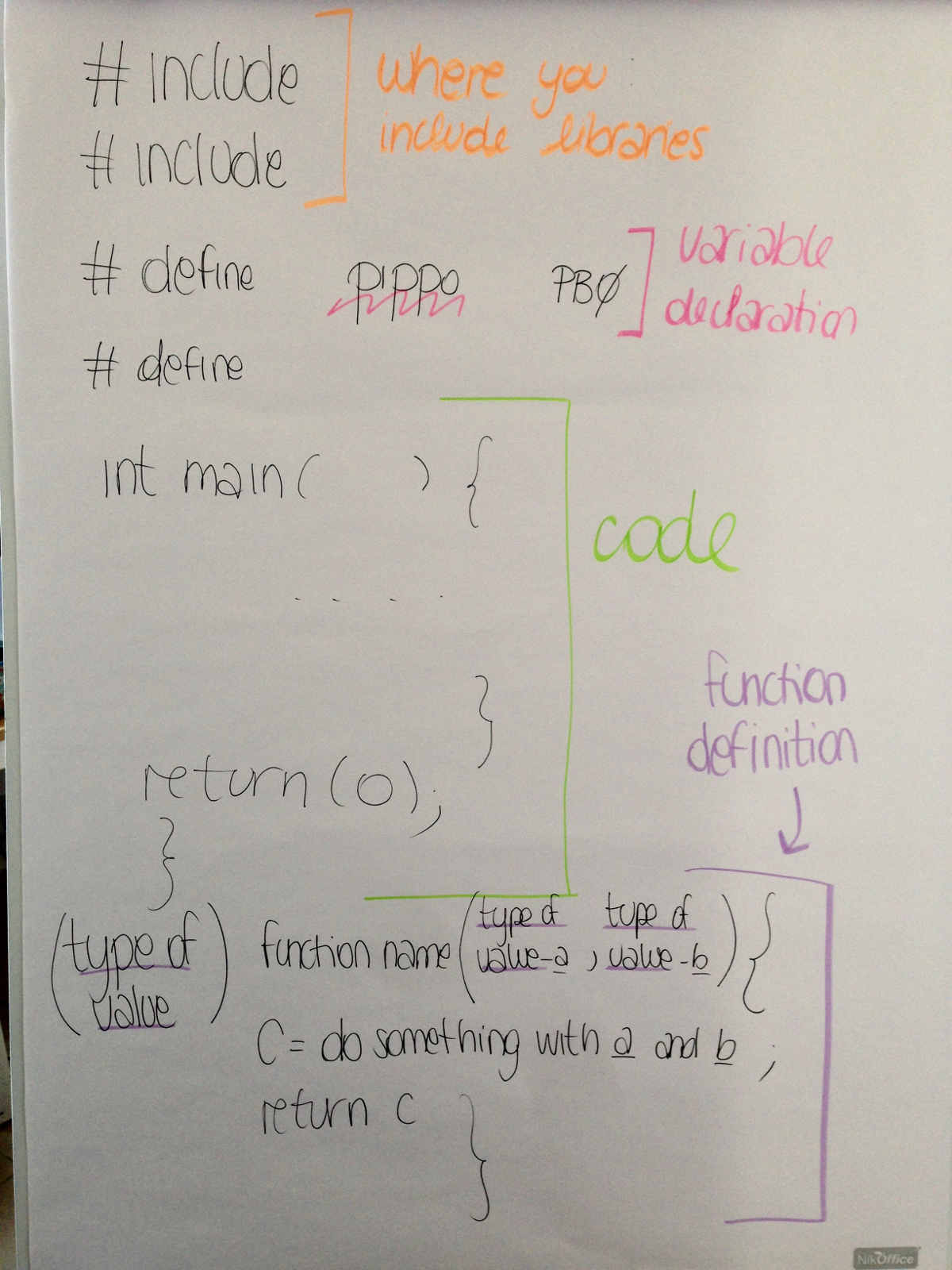
Referring to Make:AVR Programming scheme, a basic C code looks like that:
[preamble&includes]

      [function declarations - not always necessary]

           int main(void){

                [chip initialization]

        [event loop]

        while(1){

        [do this forever]
}

        return(0);

      }
To do some exercise, I found a nice blinking code on
Flavio Lampus' documentation:
 It was easy to identify main parts of C file (preamble, declarations, main) but in going further I had difficulties with
logical operators and value definition functions in main part.
It was easy to identify main parts of C file (preamble, declarations, main) but in going further I had difficulties with
logical operators and value definition functions in main part.
...Me when looking at someone else's code:

MATHEMATICAL AND LOGICAL OPERATORS
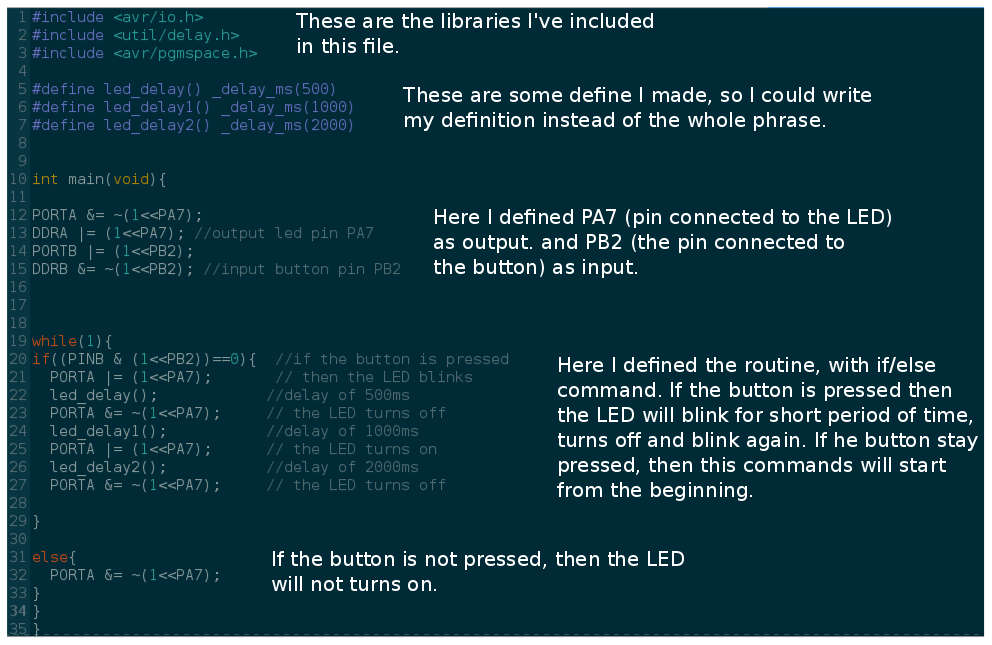
I found on the internet this tutorial that really helped me a lot.
Starting from the image above, if condition can be interpreted in these steps:
PINB is the register that gives you back PORTB values;
PB2 is the the third position (from right end) in PORTB "memory slot"( that corresponds to PB2 pin, where button is wired)
brackets define operations order, so you have to start from inner ones.
1. Initial value of PINB is 0 in all cells: 00000000
2. (1 << PB2 ) set 1 in third position (from right end) of PORTB that now looks like 00000100
3. the & operator compares two 8-cells rows and gives back 1 just if in both rows it finds 1 in the same position, so the condition declared requires PINB and "new" PORTB have no 1 in same position.
line 12-23-27
1.PORTA is defined with a negation and an "and" operations starting from initial value 00000000
2.from 00000000 with (1 << PA7) function a 1 is put in seventh position (from right end): 01000000
3.with ~ you gain the opposite sequence of PORTA with PA7 as 1 : ~(01000000)= 1011111
4.& operator compares PORTA with the negation above giving one just if both sequences have 1 in same position:
(00000000)-(01000000)=(00000000)
Reading ATTiny44 datasheet
Once I made myself an idea about programming world, facing with technical stuff looked much easier.
Even just from the very
beginning I found lots of interesting info:
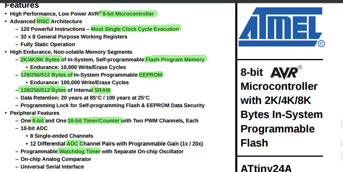
- 8-bit microcontroller: all the memory slots are 8-bit long
- RISC: this type of architecture gave faster running but littler instruction range (120 max)
- Single Clock Cycle execution: faster running means that almost all actions are as long as clock cycle (clock is something like an impulse sent millions time per second so as to give microcontroller a sense of time); knowing instructions running time allows to know program total lasting time
- Flash, EEPROM and RAM: memory types explained above - flash memory space is given by microcontroller name: ATTiny24, ATTiny44, ATTiny84
- 8-bit and 16-bit timers: beside beating time, they can also produce signals and control some sensors
- ADC are important for analogic signal analysis
- Watchdog timer: this important feature helps in too long or incorrect instrutions handling and forces microcontroller reset if an instruction performance is running out of time; it has an internal oscillator that can works at different frequencies from clock ones
- debugWIRE: it allows to show all contents of microcontroller memory and to develop programs step by step so as to help debug;
- SPI port: it permits to load program on microcontroller using an ISP programmer;
- interrupts: microcontroller subsystem which can give control values to pins (external interrupt) and generate signals to control output devices (internal interrupt);
- stand-by and low power mode: when some internal peripherals are not in use they can just switched off or they can be activated just for little time when needed;
- Brown-out: it switches off the microcontroller when input voltage is too low for working well;
- on-chip temperature sensor: this device turns off microcontroller when internal temperature gets too high (+85°C);
- internal oscillator: internal clock (1 to 8 Mhz)function can however be replaced with a more precise external resonator's one (20 Mhz in case of helloboard)
- 14-pin PDIP: microcontroller pin number and package (SMD);
- Speed Grade: voltage determines working speed and has a minimum required to reach high Mhz levels (example: to go up to 10 Mhz, 5.5V are needed)
- Low-power: this types of applications requires low voltage and so you can't work at more than 10 Mhz (example:at 1Mhz current measures 300 µA and 1.8 V)
How are all these functions linked together? To see logical connections among them, you have too look at this picture:
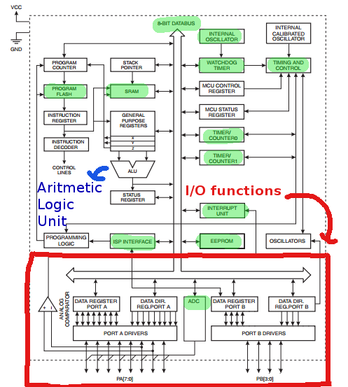 ALU: it is where mathematical operations are done.
My first C code: blinking LED
Now that I understood almost all programming instructions talk to I/O registers, I could better understand also Flavio's code.
Taking inspiration from it, I tried to write it step by step again and to make necessary-to-my-board-design changes. From page 2 of
datasheet I tried to figure out to which
pins I linked the LED and the button to.
 In my case, connections looked like this:
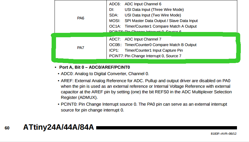
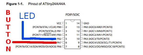 To understand their function I looked up in the datasheet again:
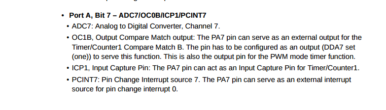
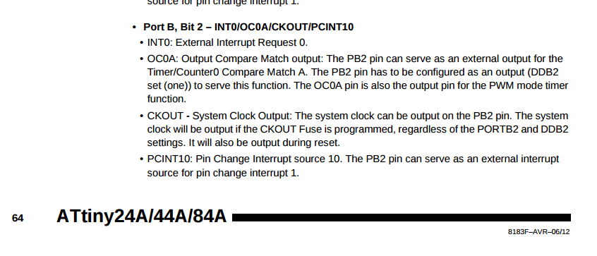 To me, PA7 would be an input and PB2 an output just like in the example code seen before.
Anyway I didn't want to copy it barely and so I downloaded GEDIT
to try editing this
blinking LED code, taken from Make:AVR Programming .
First of all I remembered myself that all the examples on that book are for ATmega128 and not for my ATTiny44, so I had
to focus on my microcontroller features in re-writing.
I then tried to understand it:
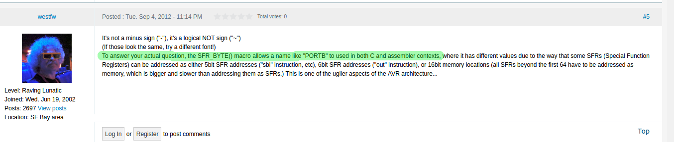
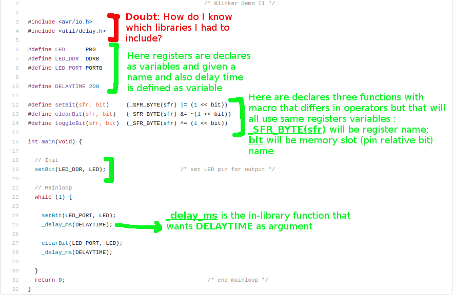 I found answers about _SFR_BYTE on a forum that said it is a conventional macro both for C and assembler languages.
 NB:
NB:
- sfr stays for "Special Function Register";
- setBit, clearBit and toggleBit are already-defined function and their #define is a declaration, not a definition! I made a scheme to clarify the difference:
LIBRARIES: what and where the evil are you??
To solve my doubt I tried with no results in looking on the internet but maybe I just didn't know what to type for my research. So I asked
my mate Pietro Rustici who (with patience and aware of my little knowledge about the topic) explained me
that on my computer somehow I already had loads of standard libraries and that if I needed external ones I had to download them
and edit the makefile. He also showed me some of these famous libraries and described their main functions from this list.
So, in the end, I understood I already had all means I needed on my notebook and I just had to undestand which functions I
did need for blinking an LED using a button.
To answer to WHICH LIBRARY HAVE I TO INCLUDE you have to think about WHAT YOU WANT TO DO.
Example: I would like to make a led blink by pressing on a switch.
Keywords:
1- LED: if I want it to blink I had to tell it somehow, so the LED will be an output and I need a function to alternate turned-off and turned-on modes.
This "alternation" in real world is a delay, so I'll need a function whose name is somehow related to delay word;
2-SWITCH: I would like it to be my previous somehow, its status should be what does activate LED blinking, so it has to be an input.
Therefore, I just need to read its status by means of PINx registers and I don't need any specific library except for one that allows me to
access I/O functionality of my microcontroller (which is < avr/io.h >).
I then went through this list I looked for libraries I needed and I found
< avr/io.h > and < util/delay.h >.
That list shows all the libraries you already have on your pc once you install gcc-avr as I did in
week 4.
Back to the example I tried to understand, I appreciated the use of functions but I postponed my practice in that only after succeeding in basic bitwise-operation-defined C writing.
MY FIRST BLINK CODE: from Gedit to terminal
I found in my mate Simone Guercio 's blink code a good starting point.
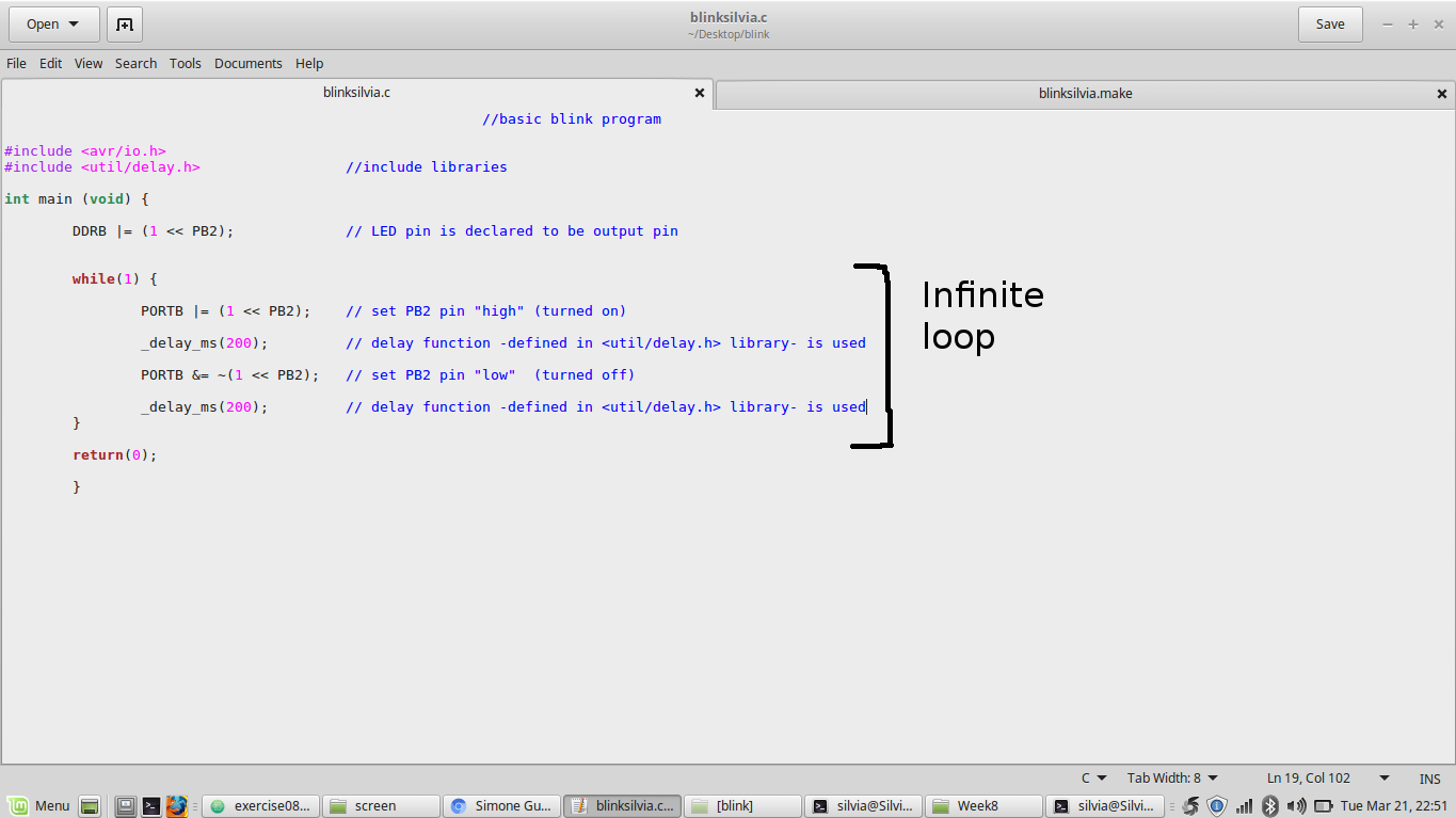
I preferred to use bitwise operations to set output pin and pin value. I so opened GEDIT and wrote my code step by step:
 NB:
NB:
- while (1): this cycle tells to repeat its internal instructions forever;
- delay value depends on clock (it has to be more than a single clock cycle)
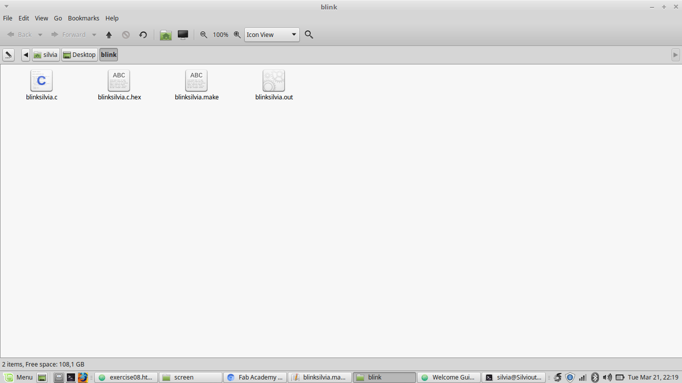
Feeling quite satisfied I saved .c file as blinksilvia.c in blink folder and I quickly moved to makefile. I didn't write it on my own but I symply edited Neil's hello.ftdi.44.echo.c.make
like this:
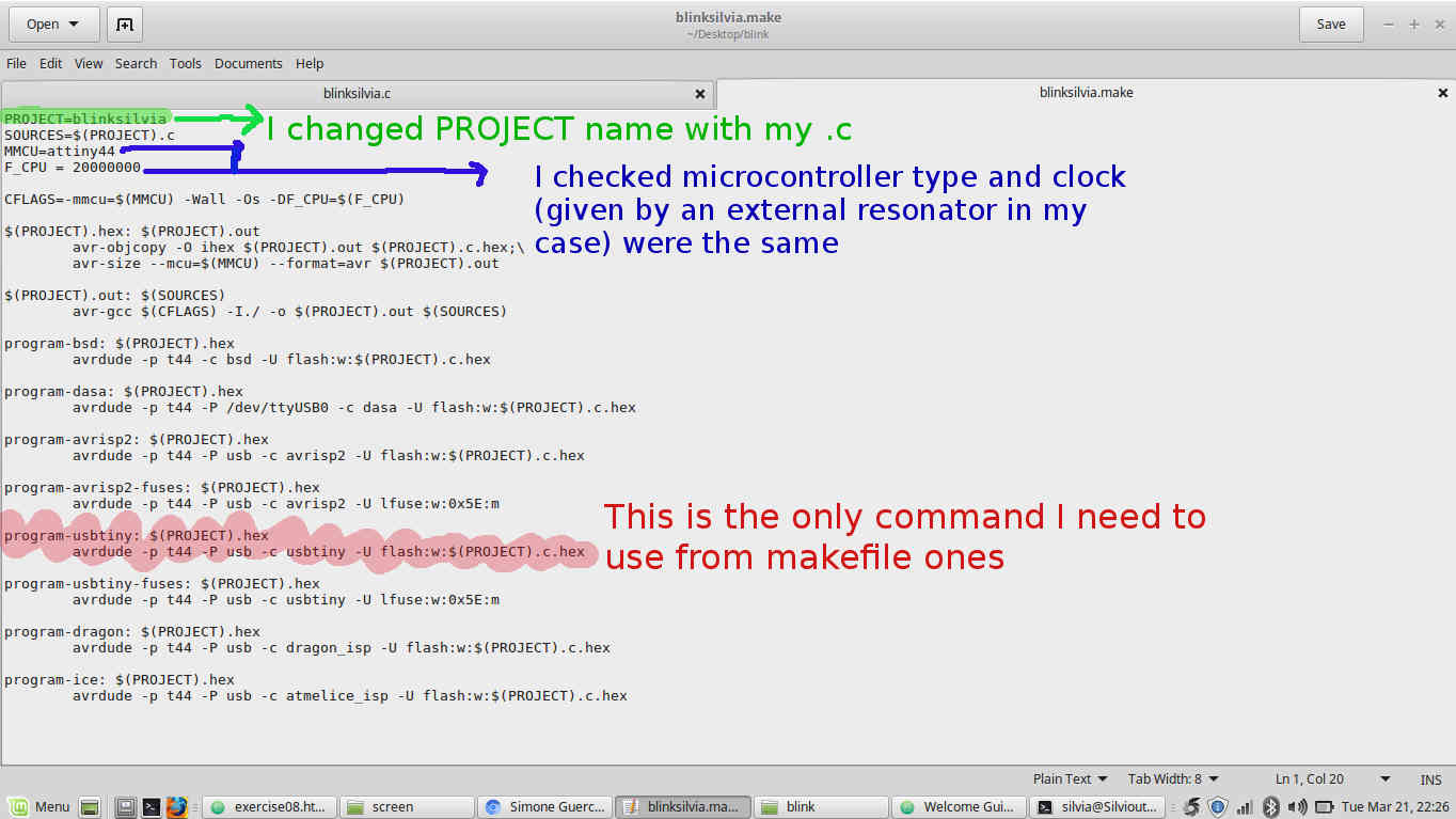 NB: this time I don't have to run
 make -f blinksilvia.make program-usbtiny-fuses because I already did that in week 6.
I then saved it in blinksilvia.c's same folder.
I then opened terminal and tried to connect my FabISP via cable but I had problem at first cause my computer couldn't recognize it ( I checked with lsusb and dmesg commands).
I imagined this problem could come from the cable itself and so I changed it. moved into blink folder with cd command.
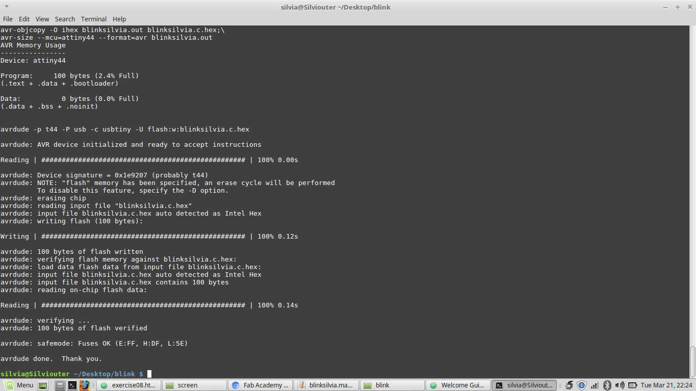
Then I ran make -f blinksilvia.make command so as to create .hex and .out files.
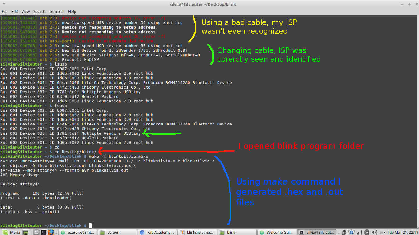
 Finally, I loaded my program on ATTiny 44 with
 make -f blinksilvia.make program-usbtiny command and....
LED blink from Silvia Palazzi on Vimeo
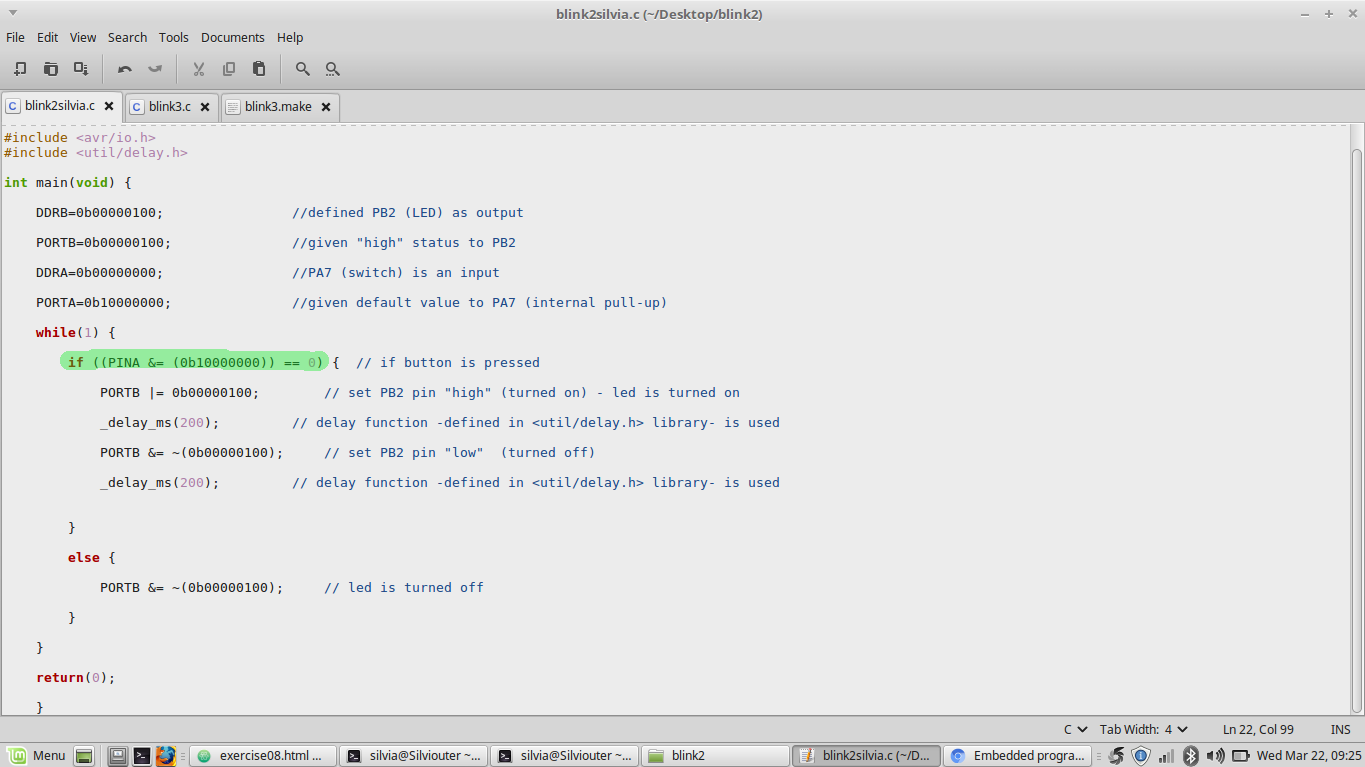
GIVING A SENSE TO MY HELLO BOARD'S SWITCH
Now I really wanted to give the switch a meaning to stay there as well and so I started thinking how cloud I edit my code:
- LED still remained an output --> I would still have to work with PORTB register;
- Switch pin (PA7) was now an input --> I would have had to check its status with PINA;
- since the switch was an input I had to set an initial value in its pin position (1) with PORTA register and so when I pressed it -condition that started while loop for LED- status would have changed into 0;
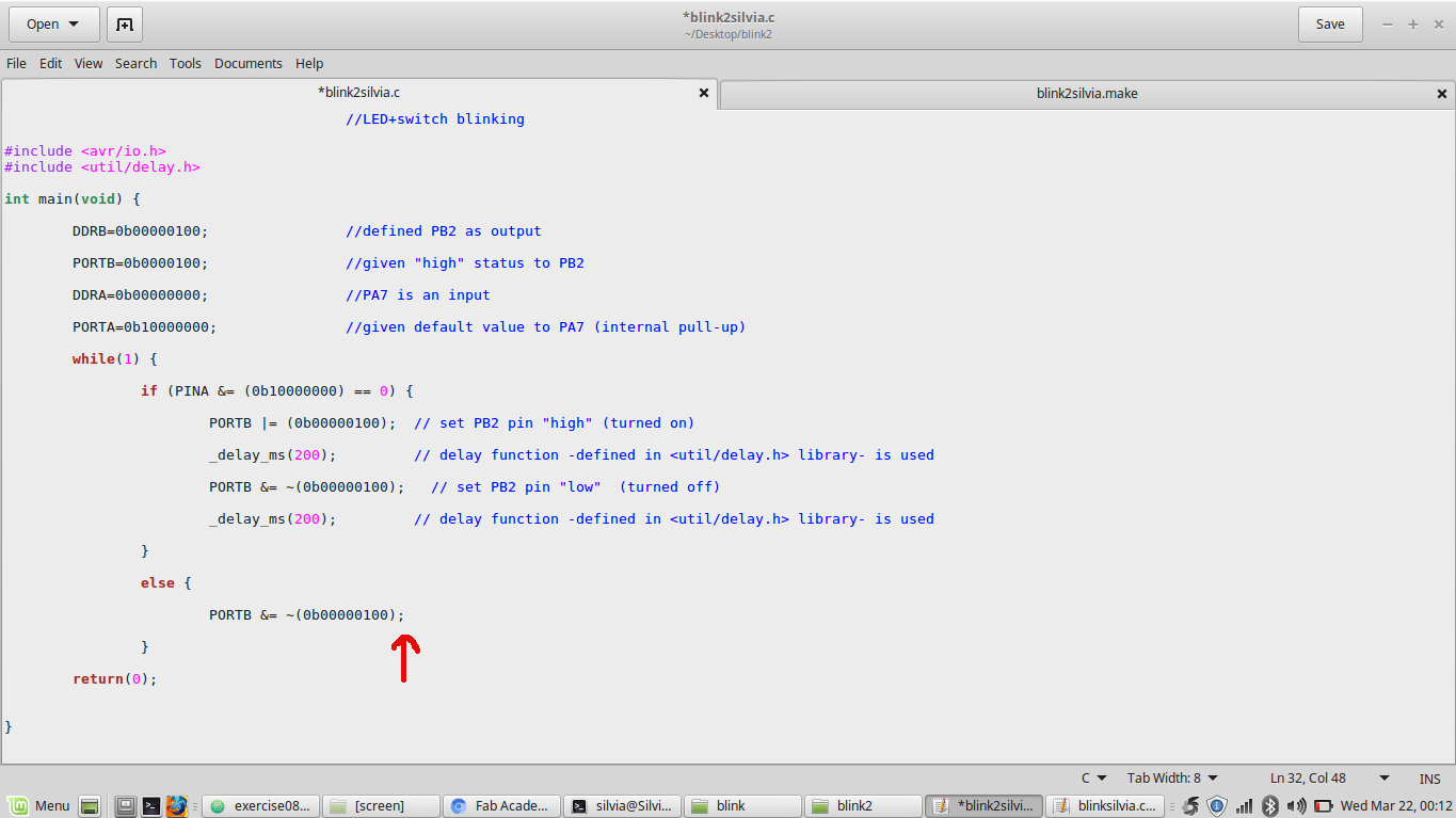
I then started typing on my own, having Luca Giacolini's example
within reach. I didn't want to use bit rolling convention this time so I ended up with a code that looked like this:
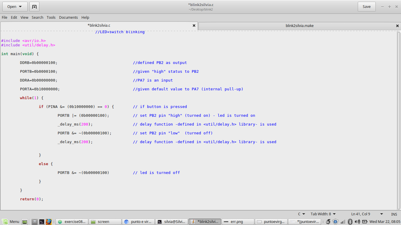 NB: DON'T COPY this code because it contains mistakes I'm going to fix below.
I was not that sure if I used bitwise operations right (can they go together with the convention I used like this?) but I tried as well to edit the makefile as before
(changing PROJECT name with my current .c file name) and repeating shell commands:
cd your/project/folder/path
Here I immediately received and error message that said:
make -f yourprojectmakefile.make 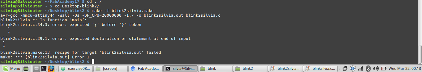 I understood I missed a semicolon:
 Trying back, I still had an error message:
 But I soon understood I missed a parenthesis:
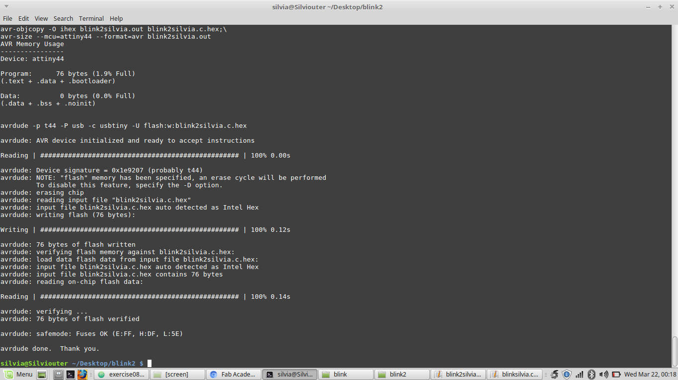
 So, re-typing
 make -f blink2silvia.make command successfully ran and so a .hex file and .out file were cretaed in my folder.
Then I tried to go on with make -f yourprojectmakefile.make program-usbtiny but I again had an error message:
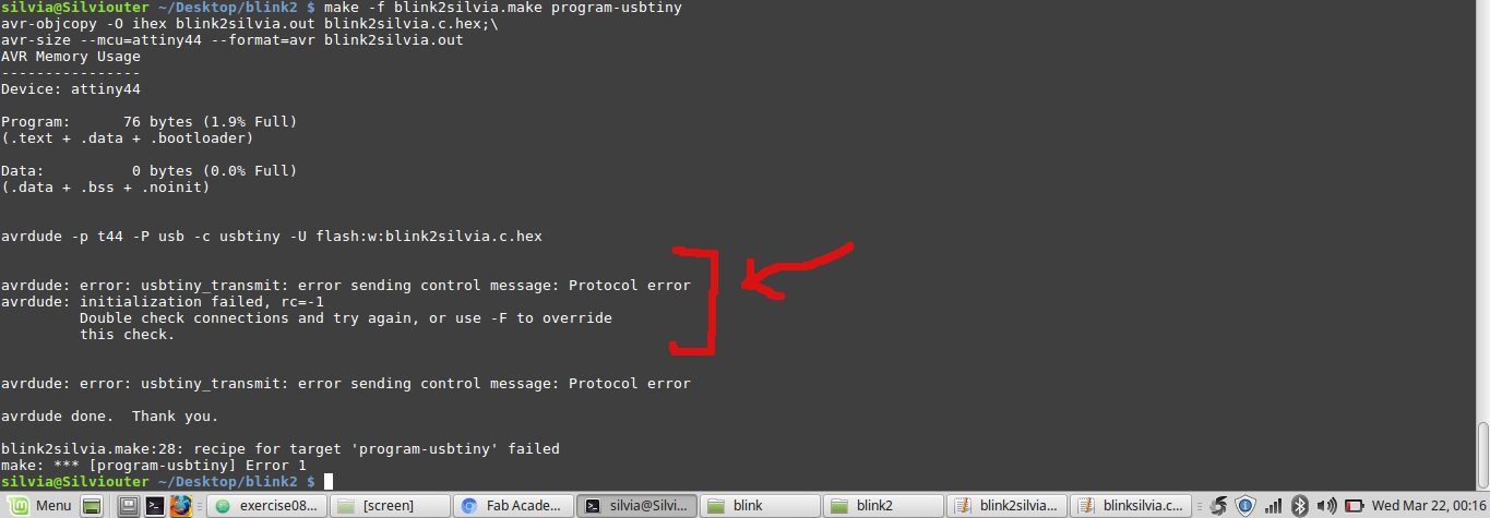 I had no idea about how that protocol error could be debugged but just before searching online, I tried to resend the command while laying my cable otspread and holding tightly
mini-usb connection of the ISP and everything worked well.
I had no idea about how that protocol error could be debugged but just before searching online, I tried to resend the command while laying my cable otspread and holding tightly
mini-usb connection of the ISP and everything worked well.
 Unfortunately, nothing blinked on my helloboard even pressing the switch more times.
I thought the error may come from the code I wrote down, so i twas then now debugging time :(
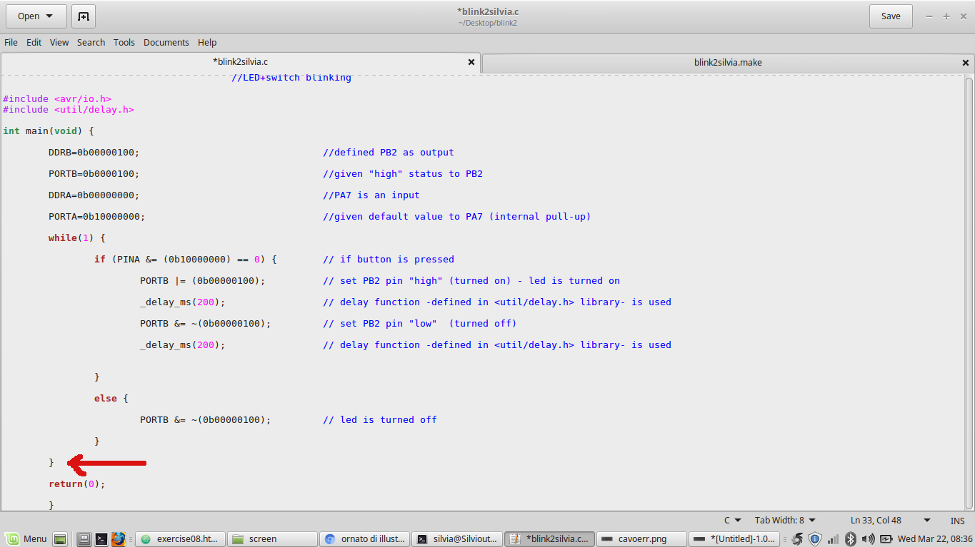
I noticed I had wrong brackets in if condition so I edited them like this:
 and running shell commands again everything worked fine :))
Button+LED blink from Silvia Palazzi on Vimeo
Anyway I was aware my code didn't make so
much sense, since once I pressed the button, LED would just continue blinking forever.
So, my intentions was to make LED blink just 2 times and then stop.
I edited my code like this:
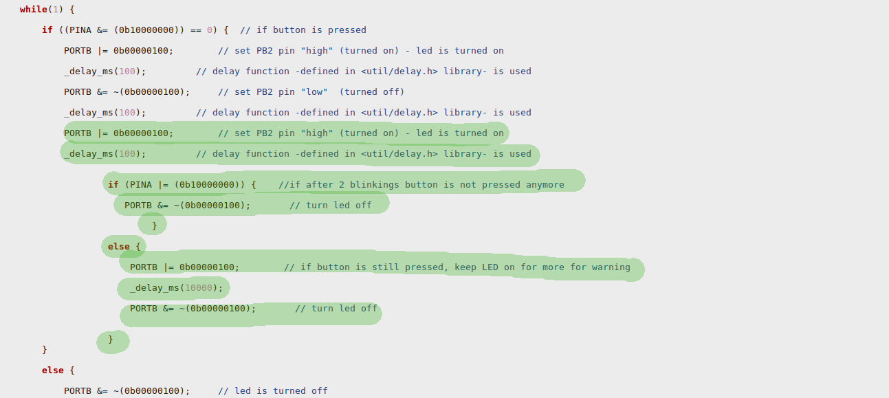 But the result was that it did want I want (If I press button, blink 2 times and then, if button is still pressed, blink longer, if it is not, turn off the LED) but in
addiction it blinked another time at the end.
But the result was that it did want I want (If I press button, blink 2 times and then, if button is still pressed, blink longer, if it is not, turn off the LED) but in
addiction it blinked another time at the end.
So I have now to degub this code and reach press-->light, press-->turn off level.
Conclusions
This week has been the hardest one to me since now , the first in which I really had no idea about anything at first but despite looking scaring a lot at first,
it revealed to be challenging so much! I felt like running faster and faster while going through some books pages or googling some obscure words: as I ran I moved forward
and I can't believe I learnt that much just in a week. I know I could cooperate more during this week, trying to solve problems together with my mates but I wanted
to give lot of importance to my individual work, since this part (programming) has always looked as an insurmountable hurdle to me.
I know
I have to study harder and harder but even just a little acquaintance with coding world made me think I would like to dive more into this new (to me) world :)