Embedded Programming
Overview
Last updated: 28/03/2016
Objectives 1.Read a microcontroller datasheet; 2.Program your board to do something, with as many different programming languages and programming environments as possible;Learning outcomes 1.Identify relevant information in a microcontroller data sheet; 2.Implement programming protocols; Have I... Documented what I learned from reading a microcontroller datasheet? Programmed my board? Described the programming process/es I used? Included my code? Summary This week I finished and programmed the Hello Board. I used two programming languages: C and Assembler. I programmed in two environments: linux terminal and Atmel Studio.
Introduction on AVR microcontrollers Given my limited knowledge on both hardware and software of electronics in general, I took for this week a knowledge-->practice approach, as opposed to what I did in previous assignments. I mainly looked at Make AVR Programming that is a nice manual for entry-level. In particular, the first two chapters really helped me in understanding what I was supposed to do during the whole week and gave me the basic knowledge on microcontrollers that I needed. After that, I also had a look at this tutorial that helped me structuring my first sketch in C.So, what is an AVR microcontroller? First of all, AVR is a product line of microcontrollers which uses the RISC architecture. In particular, for this week I focused on the ATtiny44. From a hardware perspective, a microcontroller is a complete computer on a single chip. On a AVR microcontroller you can find: 1.CPU (Central Processing Unit) that processes 8bits at a time; 2.Internal clock that runs at about 8MHz.It can actually substituted with an external crystal, up to 20MHz; 3.Flash memory of 1-32KB where the sketch is host; 4.RAM memory of 1KB; 5.Input pins which are digital; 6.Output pins which are digital; Eventually, AVR microcontrollers can not support an operating system, meaning that they can not execute multiple tasks at a time.
ATtiny44 datasheet The ATtiny44 datasheet is a pretty large manual that contains different kinds of information/resources on this specific type of microcontroller. Information vary from architecture description to code samples. The document is in my opinion rather difficult to navigate, especially because it seems there is no hierarchy in the way things are presented. In order to get started I needed some basic information on the pins layout.
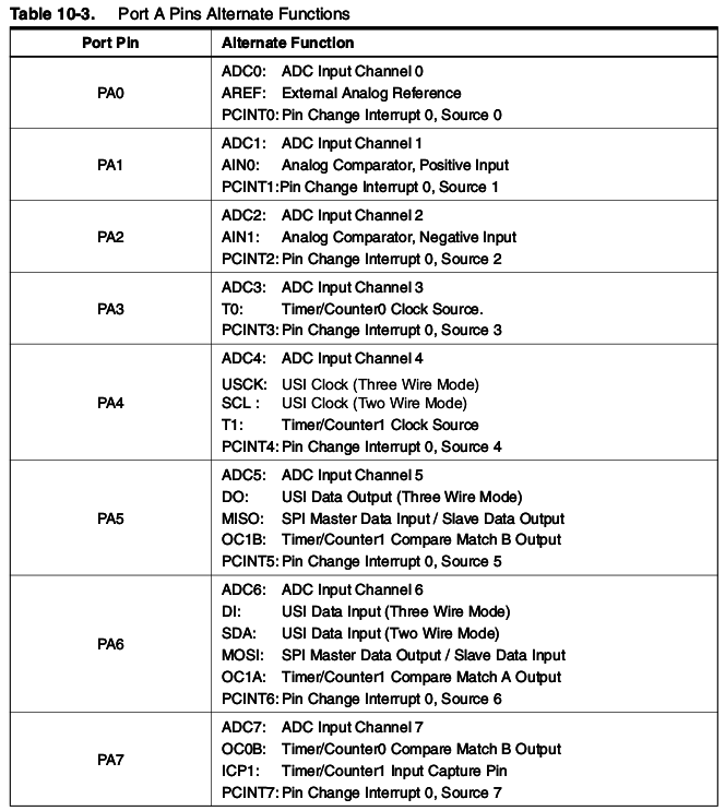
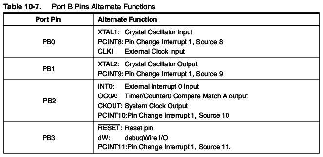
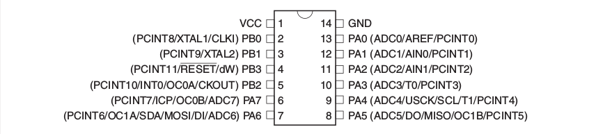 Furthermore, I checked out which pins could do what, also trying to make sense of the Hello Board that I had already built, where I used PB2 as output and PA7 as input.
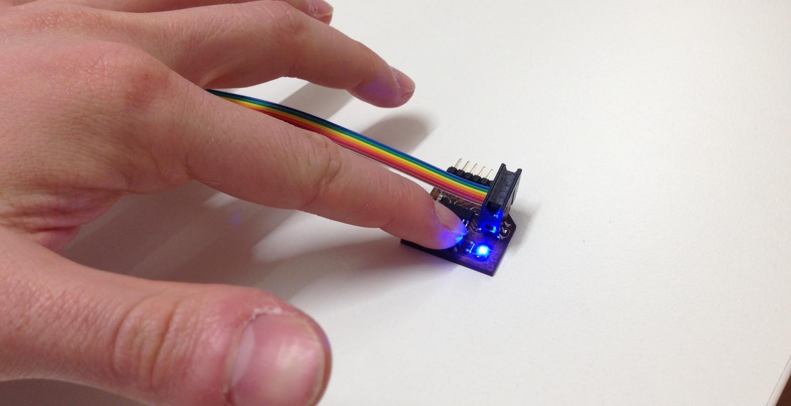
Producing the Board The echo-hello board was produced during week6, even though it eventually only worked this week, thanks to the special help of Emma at Waag Society, Amsterdam! After I had to de-solder and solder the ATtiny again and again, I appearently burned the chip. PB3 was internally connected to PA5. Eventually, I "borrowed" a new microcontroller from Waag and the board got recognised with the terminal command:
avrdude -c usbtiny -p t44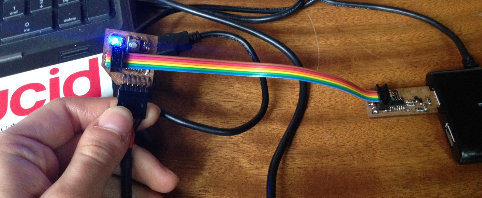
Programming in C + terminal The first programming environment that I used was the linux terminal, as I had already used it before. The first sketch that I made was a simple blinking LED, written in C and compiled with avrdudude and this makefile. In order to understand what registers do, I used two tutorials, that seemed much more accessible to me than the datasheet itself. In the first place, this tutorial explains what registers are and how to set up input-output pins on the ATtiny. In the second place, I copied and adapted this code [1], which is nicely explained in details.
//importing the necessary libraries (avr/io, avr/delay)
#include < avr/io.h>
#include < avr/delay.h>

int main (void)
{
  //Set PORTB to all outputs
  DDRB = 0xFF;
  //create an infinite loop
  while(1)
    {
      //turns B2 HIGH
      PORTB |=(1<<2);
      _delay_ms(20);
      //turns B2 LOW
      PORTB &= ~(1 << 2);
      _delay_ms(20);
    };
}
//importing the necessary libraries (avr/io, avr/delay)
#include
#include

int main(void)
{

  //Button pin A7 as input
  DDRA &= (1 << PA7);
  PORTA |= (1 << PA7);
  //LED pin B2 as output
  DDRB |= (1 << PB2);
  PORTB |= (1 << PB2);
  //create an infinite loop
  while (1)
  {
    //if the button is not pressed, LED is low
	  if (PINA & (1 << PA7))
      {
        PORTB &= ~(1 << PB2);
	    }
    //if the button is pressed, LED is high
    else
          {
    	       PORTB |= (1 << PB2);
          }

  }
}
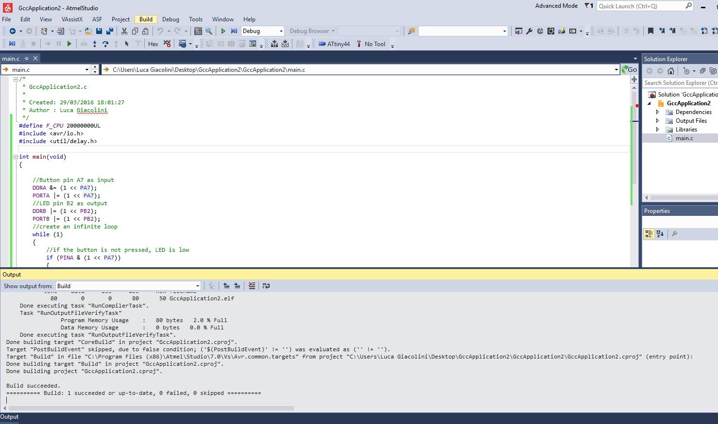
Programming in C + Atmel Studio I opened Windows again, hope God will forgive me. Atmel Studio is a really intuitive and structured software for compiling and uploading C, C++ and Assembler sketches to an Atmel microcontroller. Two downloads are necessary: 1.Atmel Studio 2.winAVR compiler Then I wanted to simply learn a bit about the procedure of uploading a sketch and I did not have enough time to actually write sketches with it. In order to load a the LED_button sketch that I previously presented, I did the following: 1.Open a new project --> GCC C Executable Project 2.Tools --> Set Profile --> Advanced (as explained here) 3.Tools --> External Tools --> Add 4.Fill Command and Initial Directory with the path to AVRDUDE 5.Fill Arguments with
-c usbtiny -p m328p -v -v -v -U flash:w:$(TargetDir)$(TargetName).hex:i 6.Build
 8.Tools --> programmer
The sketch got successfully uploaded!
8.Tools --> programmer
The sketch got successfully uploaded!
Programming in Assembler + terminal Assembler is the closest language to machine language that can actually make sense to humans. It can not be unlinked from the physical architecture of the microcontroller, which seemed to me a good reason to start looking a bit into it, even though the learning curve was the steepest ever. At first I looked for help on the repository of my tutor Fiore, who wrote a sketch in assembler to obtain a blinking LED. At first sight, I did not understand a single line of his code. This tutorial really put me on the right track. In particular, the pages on registers and ports also helped me making sense of what I had previously done in C. With the ATtiny44 datasheet, this reference manual opened in the background and the documentation of John I tried to make sense of Fiore's sketch, written for the hello board. I commented with what I believe each line of code does [3]. Please forgive me if some interpretations are incorrect. The suggested structure would be: 1.header with author and copy(left) information
    ; Simple Blink in ASM
    ; Editing the work of Fiore Basile - FabAcademy 2014
; Public Domain ; the file tn44def.inc needs to be included within the same project folder
; I have tried to make sense of that file, but I honestly can not understand what goes on there
.include "tn44def.inc" ; ports are gates from the internal CPU to the external hardware/software
; the amount of ports depends on the type of microcontroller
; ports have a fixed address to establish communication with the CPU
.equ led_pin = PB2; led pin is PB2
.equ led_port = PORTB; comm port
.equ led_dir = DDRB; comm direction
.equ led_pins = PINB; comm pins ; defining the variable delay
.equ delay_time = 20; ; registers are storages with 8-bits capacity. In AVR registers go from R0 to R31
; registers can be renamed, which is what happens in the next 6 lines
.def bitcnt = R16; bit counter
.def temp = R17; temporary storage
.def temp1 = R18; temporary storage
.def counter1 = R20;
.def counter2 = R22;
.def counter3 = R21; ; CSEG and ORG are statements that I did not fully understand.
; However, I figured that the following three lines reset the interrupts handlers
.cseg
.org 0
rjmp reset reset:
;
; set fuse low byte to 0x7E for 20 MHz resonator
; set clock divider to /1
; CLKPR is the clock prescale register, as described on the datasheet at page 31.
ldi temp, (1 << CLKPCE)
ldi temp1, (0 << CLKPS3) | (0 << CLKPS2) | (0 << CLKPS1) | (0 << CLKPS0)
; store register I/O location
out CLKPR, temp
out CLKPR, temp1 ; set stack pointer to top of RAM
;
ldi temp, high(RAMEND)
out SPH, temp
ldi temp, low(RAMEND)
; store register I/O location
out SPL, temp ; clear Bit in I/O Register
sbi led_port, led_pin
sbi led_dir, led_pin loop:
; the SBI (Set Bit in I/O) instruction can be used to toggle one single bit in a port
sbi led_pins, led_pin ; toggle led pin
rcall delay
; the CBI (Clear Bit in I/O) instruction can be used to toggle one single bit in a port
cbi led_pins, led_pin
rcall delay
rjmp loop
; loads the value in delay_time on register 21
delay: ldi counter3, delay_time
;
delay1: rcall counta
dec counter3
; BRNE is branch if not equal
brne delay1
; RET is retourn from subroutine
ret
; loads the value 0 on register 20
counta: ldi counter1, 0
; the fact that the function calls itself does not make sense to me, just like it happens later with pauseb
pausea: rcall countb
dec counter1
brne pausea
ret
; loads the value 0 on register 22
countb: ldi counter2, 0
pauseb: dec counter2
brne pauseb
retsudo apt-get install avraavra NAMEFILE.ssudo avrdude -p t44 -P usb -c usbtiny -U lfuse:w:0x5E:m
sudo avrdude -p t44 -P usb -c usbtiny -U flash:w:led.s.hex
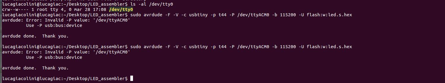 After removing that part, the sequence of action was successful and the sketch got loaded.
Conclusions During this week I had the first encounter with what true physical computing is. Before, I had largely used Arduino, which does not really give you an idea of how the hardware of a microcontroller is connected to its software counterpart. It was difficult, yet really interesting to deepen in such topics a bit more. I really liked C as a programming language, while I found Assembler a bit too complicated for a basic coder like I am.
Table of Content
Resources
- [1] LED_blink in C
- [2] LED_button in C
- [3] LED_blink in assembler
- [4] Atmel Studio