DOWNLOAD FILES
3dprintedgears.stl
LasercuttingFiles.dxf
Mould.stl
Algorithm.3dm/.gh
Week Assignment
Week 01 - Principles and Practices, Project Management
Week 02 - Computer-Aided Design
Week 03 - Computer-controlled cutting
Week 05 - 3d printing
Week 10 - Outputs
Week 12 - Molding and Casting
Week 13 - Input device
CONCEPT
As final project, I would like to create an interactive shading system which can have a double behaviour: as a "background program", which I will define "idle", the shading system will optimize the gain of light, according to the position of the Sun. I will use Ladybug + Honeybee to obtain the data about the Sun path in a certain geographic position.
A LDR and a temperature sensor, will give me 2 variables. When clouds will be detected, the shading system will allow the light to come inside the building, when the temperature will be too high or to low, the shading system will balance the gain of energy. I will use also the temperature to calibrate the Ultrasonic sensor I will fix in the front.
The second behaviour regards the human interaction. Four ultrasound sensors will detect the presence and the distance of people. Once detected a body, the shading system will open creating a perspective view and letting people see what is beyond the shading structure.
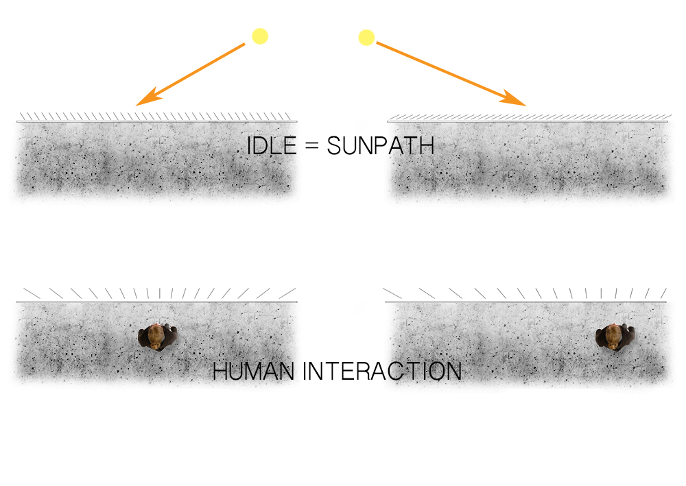
One of the major problems regarded the shading units motion. If I will add 100 shading panels, I cannot use 100 stepper motors + drivers. So I spent some time to figure out a system to let the units move in a parallel way when in idle function, and to move in a radial configuration when people are detected.
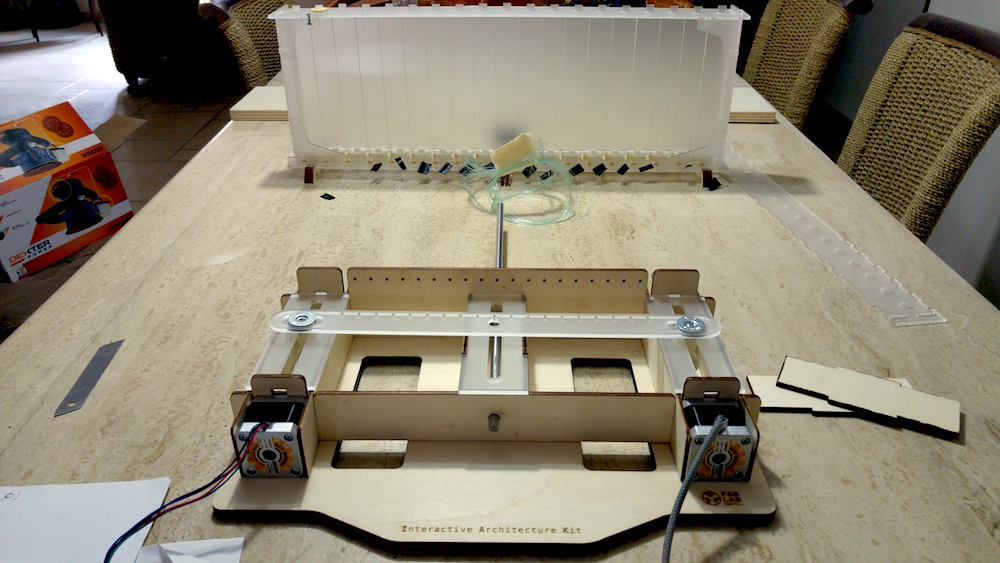
For that reason, I thought about a machine with 2 stepper motors, which will move a bar, where wires will be fixed on it. All the wires will be connected to each shading unit. The movement of that bar will allow different configurations for the shading units. I created some video and gif to understand better this process.
Next step will be to create and produce the machine and realize a prototype of a shading unit, which will be made by fabric.
Mechanical Design
FIRST TESTS
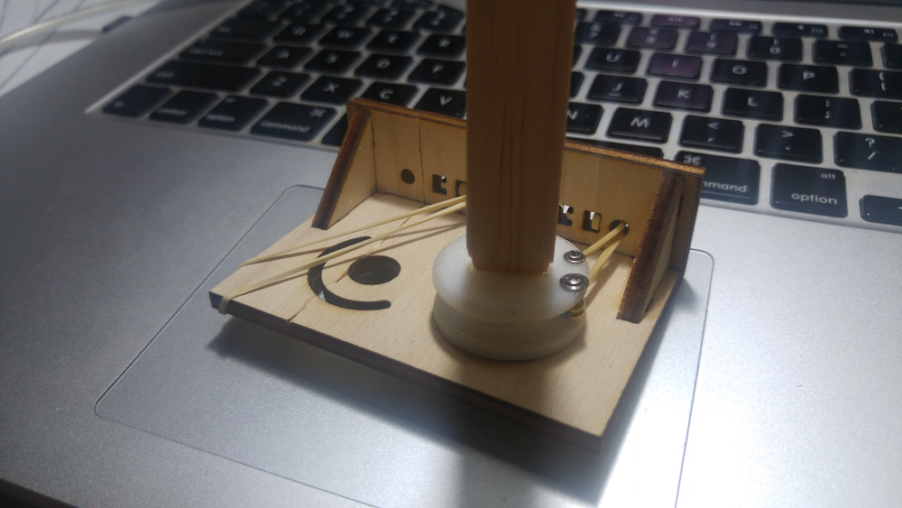
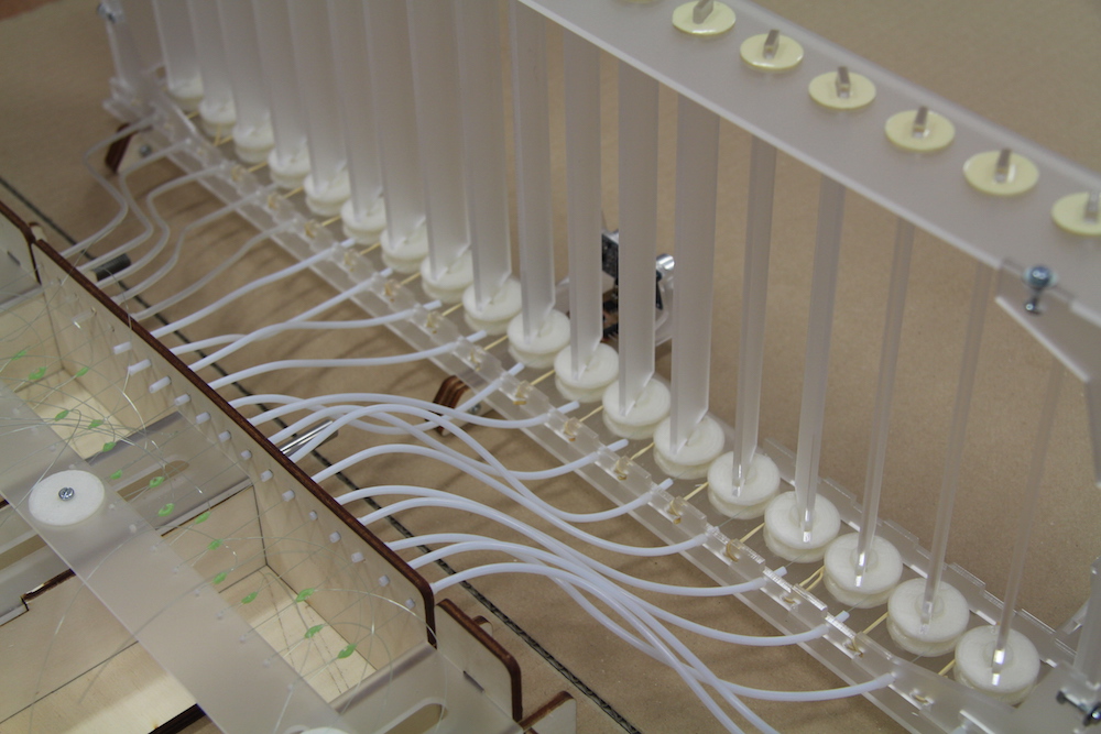
This week I spent a lot of time to give the project the right dimension and thinking about the materials I will use and the mechanical parts. What concerned me the most was the shading unit system. I needed something, with a spring, that will allow me to have each shading unit in traction, so that everytime the "machine" (I will call it Console from now) will release the wires, they will roll up around the reel. I made a 3d model and 3d printed the reel and the base. I also designed a 180 degree arc so that I will have a kind of endstop.
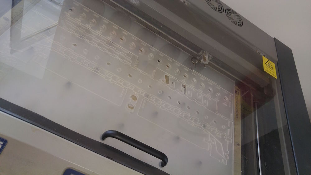
After cutting with Epilog lasercutter a sample of the frame, I fixed the gear for retraction with a rubber band and tried the mechanism. It works! Now will proceed to realize in large scale from a panel of plexiglass 600x420x3mm.
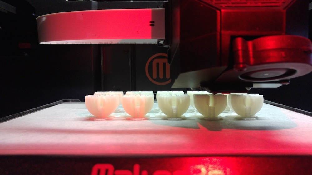
PRODUCTION - 3D PRINTING
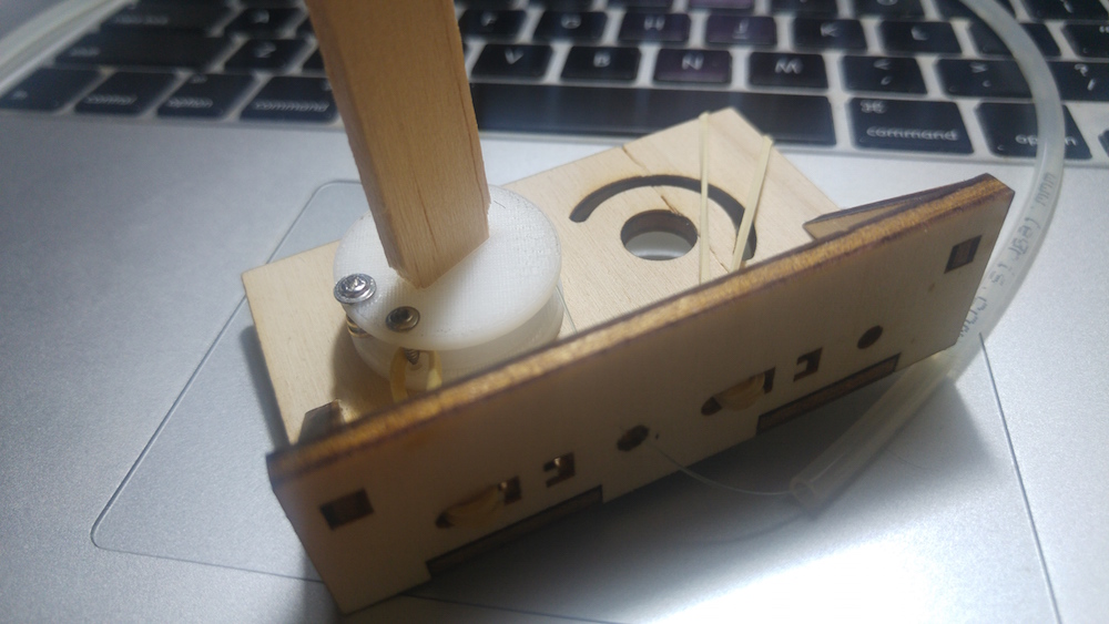
After this test I realized a lot of things. First of all, to make a good design and to make the frame and the units more stable, I will apply another layer of plexiglass on the top of this gear. For that reason I needed to improve the shape. I have loaded on sketchfab the final version of that gear. After 3dprinting this part, I tested it again and it was working good. Then, I understood that, for these part, a mold and casting process would be not advantageous in terms of time, details and complexity of the shape and holes inside of that. As a matter of fact I 3d printed all these gears in less than 9 hours of printing.
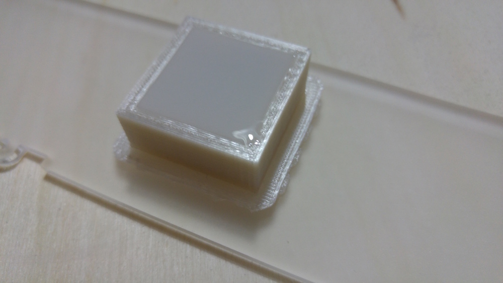
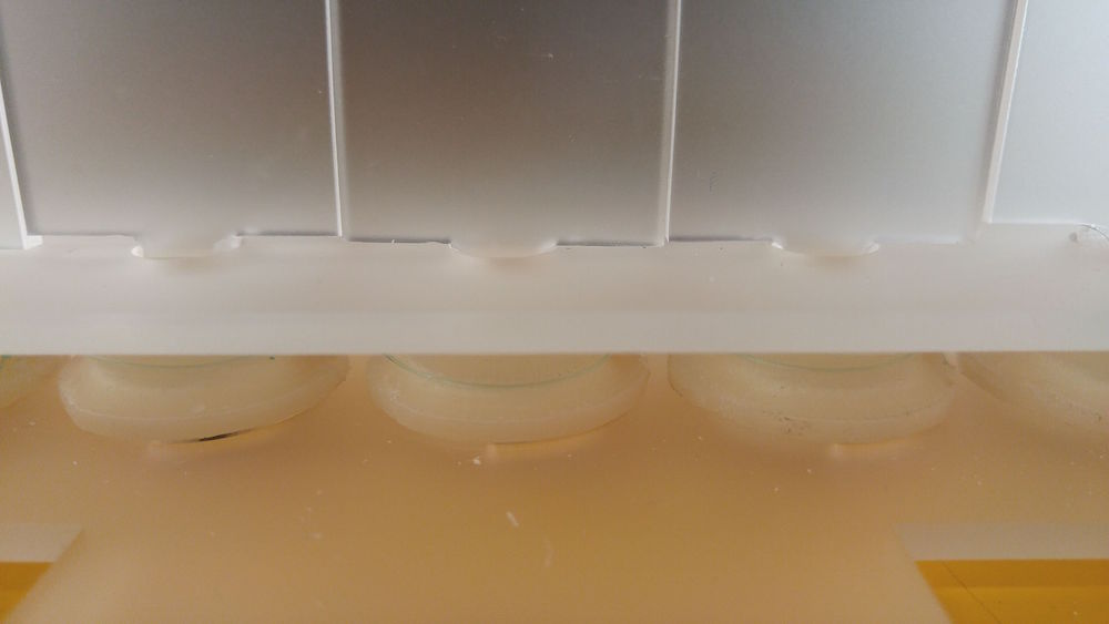
PRODUCTION - MOLD AND CASTING
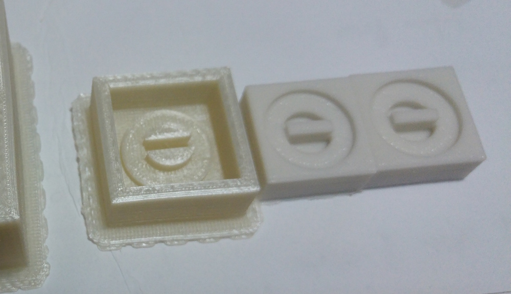
Moreover, I also focused on the upper part of the shading unit. Since the lowest part will be fixed by those spinning gears, the upper parts are useful just to keep the shading units straight. Because of the simplicity, this upper part was very easy to reproduce by mold and casting process.
It took me approximately 30 minutes to produce the mould shape, then 2 hours to produce the silicon rubber moulds (to improve productivity I have realized 2 moulds). I prepared the silicon rubber for mixing. The one I used is this one, the MM810 from ACC silicones. After reading the Technical Sheet, I used a scale for weigh both components: the rubber base on one side and the catalyst on the other side, whose weight must be 5%.
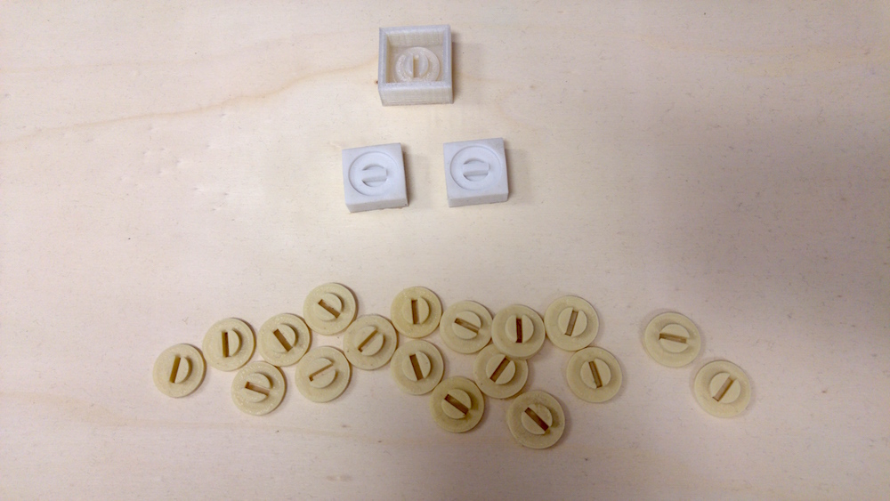
Then, concerning the resin, I used Polyurethane Resin Sintafoam, from Prochima. Here is the Technical Sheet
Instead of measure the weight, I have measured the volume of each one, which ratio must be 50%-50%. By so doing,every 20 minutes I have been able to produce 2 parts in resin.
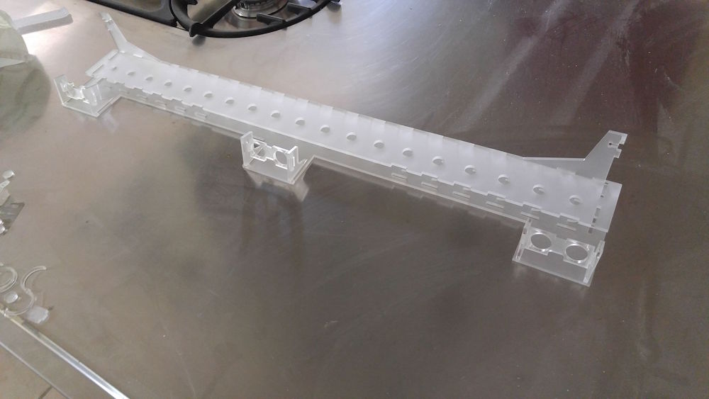
PRODUCTION - LASERCUTTING
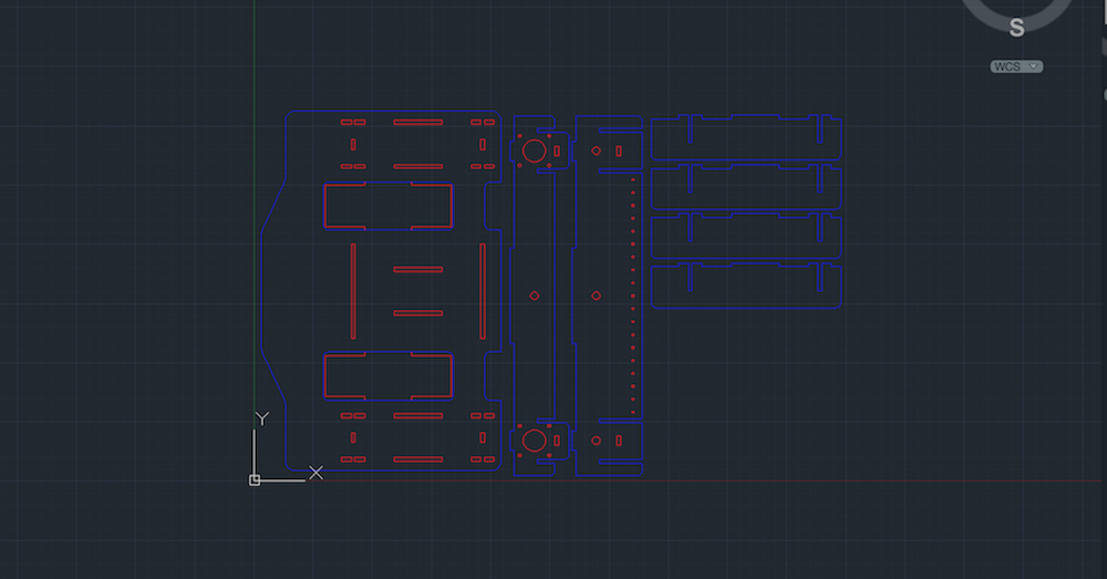
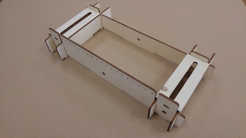
In the meanwhile I prepared all the files for laser-cutting process. Since I will be using 2 different materials, plexiglass (3mm thickness) and plywood (4mm thickness), I checked if all the joints were exact, leaving the right gap in terms of kerf and interference. I used plexiglass for the shading frame and the units, while I used plywood mostly for all the parts componing the machine (or console). I used autocad to draw the lines, then importend in Rhinoceros and made a 3d model to check if every piece would match. I splited all the curves in 2 layers, the red lines represent all the inner lines, which will be lasercutted first, whilst the blue lines represent the outer lines, cutted in the end.
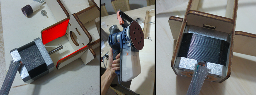
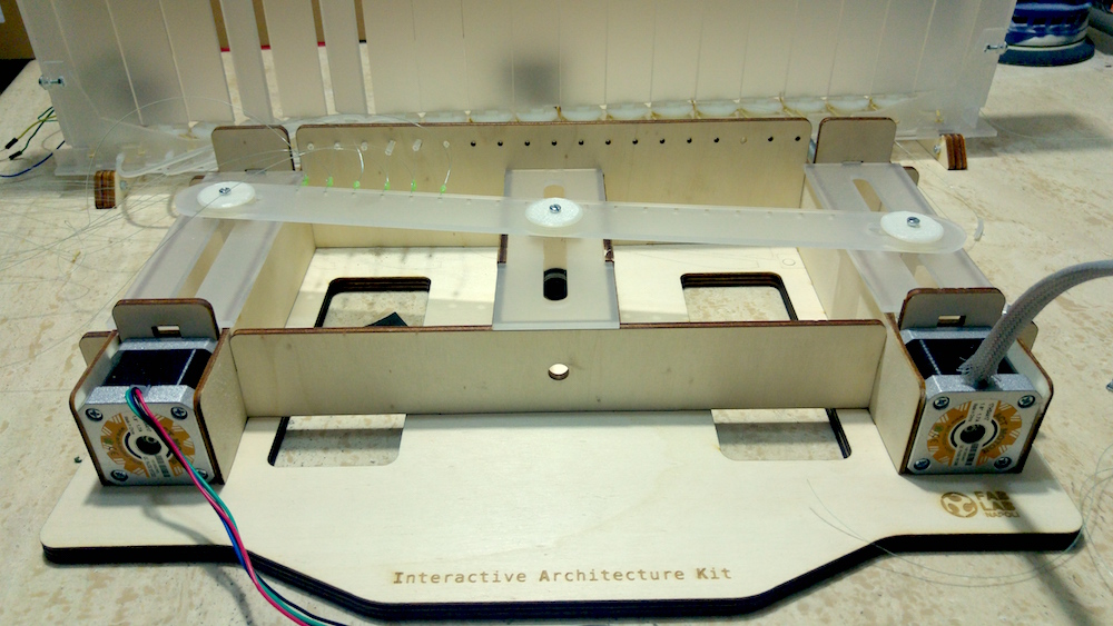
Unfortunately, I realized that I have made a mistake concerning the frame. The NEMA stepper motor did not fit because I did not leave enough space ( I needed 2mm more). I decided to not cut again the frame since it would be a waste of material. For that reason I took a sander and put away some matter, enough to fix the stepper motor in it. This issue is documented in the next picture.
Concerning the shading system, I created the 2d curves using Autocad, dividing everything in 2 layers.
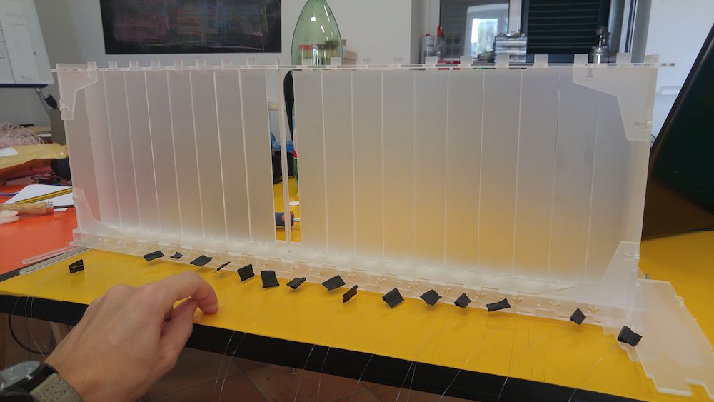
ASSEMBLY
Next step is to assembly all the pieces together, to make them work. About the shading unit, I imagined to use a spring system which allows to each unit to come back when the wire will be released. I attached the line (for fishing) and the rubber band to the gears and fixed them into the frame for shading system.
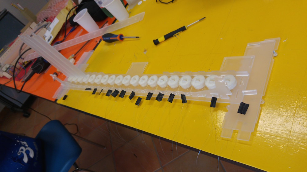
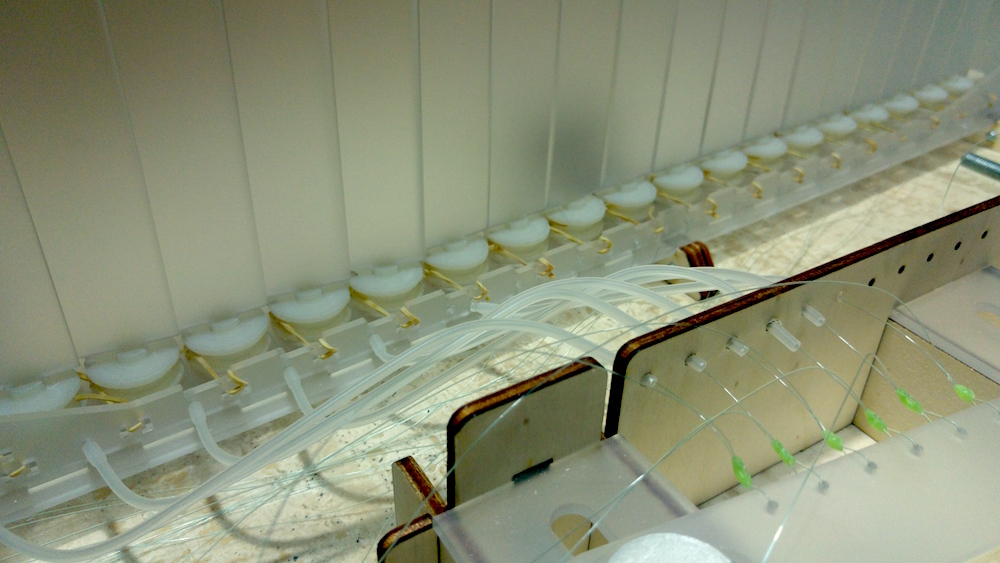
Concerning the electronic I used for the first tests Arduino+Cnc shield and attached the board from input device. I will try also to use the board (showed in the next picture) produced in Moscow, creating a network of 3 Hc-Sr04.
During these finale steps, I fixed the tubes and connected the wires to the console "bar". I also 3d printed the guides which will trasmit the motion from the threaded rods to the bar. Next step will be calibration and connection to the Grasshopper Algorithm, first using a CNC Shield + Arduino (flashed with firmata), then with my own board.
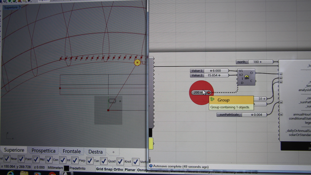
I created the Algorithm with Grasshopper using Ladybug to get the Sun Vectors. With a Ladybug component (Download .epw) I have downloaded the epw file which gives to grasshopper components information regarding the location, geographical coordinates, temperatures, speed and directiond of the wind during the year etc etc. Then I got the rotation of the shading units which I converted is steps for the stepper motors. I also created some variable when HC-SR04 detect people or object coming closer. I used Pick and Choose component to create variables so that everytime an object will be closer then 600mm to the shading system, the shading units will stop to follow the sun and will rotate in a radial way.
Here is the final results:

Quest'opera è distribuita con Licenza Creative Commons Attribution - Non commercial - Share-Alike 4.0 International.