Produce a PCB, weld the components and program the chip
1. Milling and Cutting a Printed Circuit Board
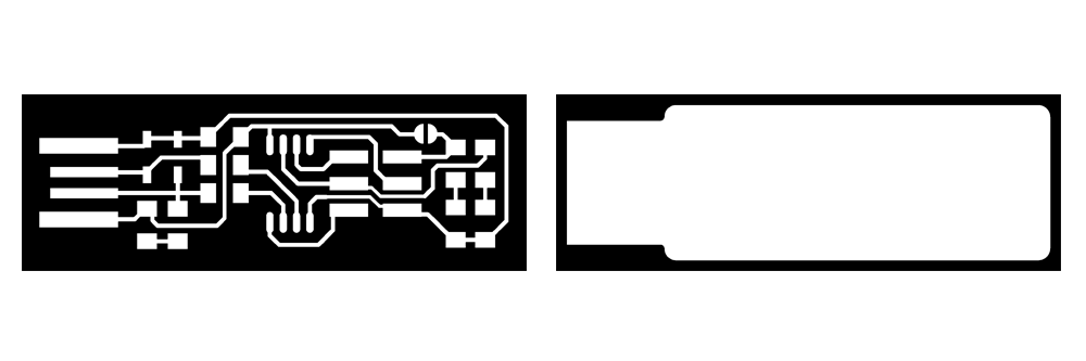
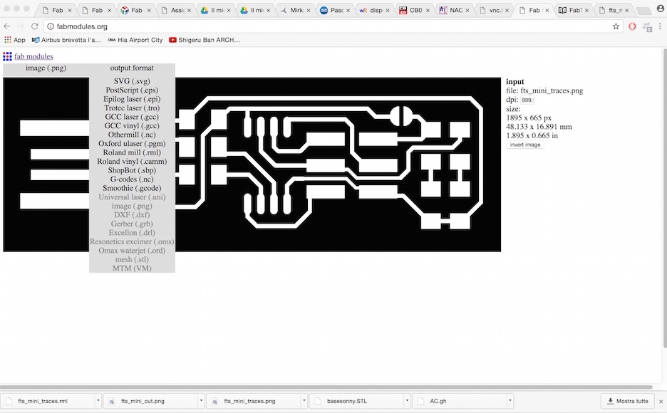
A Printed Circuit Board is a circuit made with different processes, like milling or etching or vinyl cutting. Instead of using point-to-point wiring, a PCB is recommenended to avoid failures at wire junctions and short circuits when wire insulation began to age and crack. Our PCB is this one, fabtinyisp. We started from a PNG image, black/white, which I loaded in FabModules.

After setting .rml as output format, I worked on the settings.
Since we are using a flat mill of 1/64", I clicked on process/PCB traces (1/64)
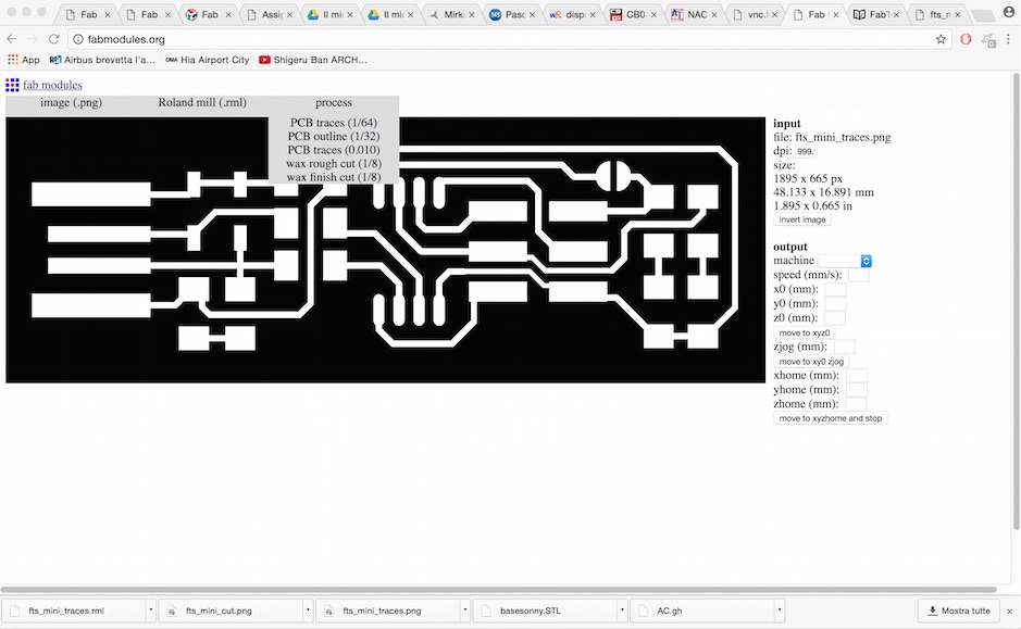
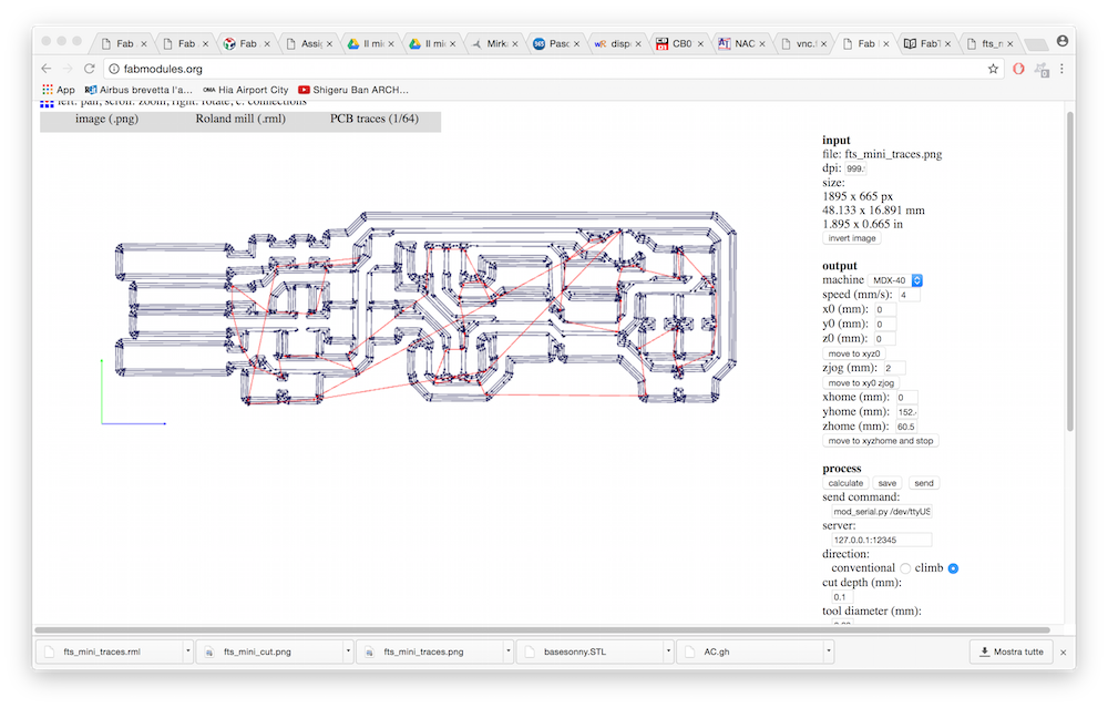
After that, I set up the machine, a Roland mdx-40.

Speed is set automatically on 4mm/s. After clicking on calculate button, I was able to see the milling paths. I have saved the files and exported to athe pc connected to the Roland MDX-40.
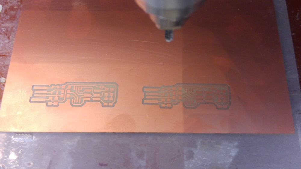
Milling and cutting with the Roland MDX-40
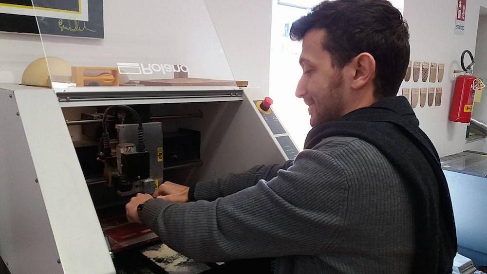
Once turning on the miller, I took a copper plate, put some tape on it and fixed on the milling plate. After settings the xyz origin on the Roland MDX-40, I have loaded the file for pcb traces and I pressed OUTPUT. The machine started to engrave the copper plate. Here is the outcome.
After cutting out all the piece, I started to weld the components with the solder, using soldering flux paste.

Then, I have fixed the resistors, capacitor, the integrated circuit ATtiny and the very small leds smd.
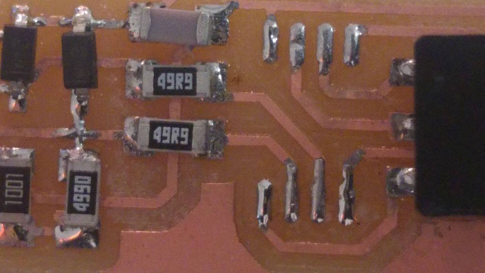
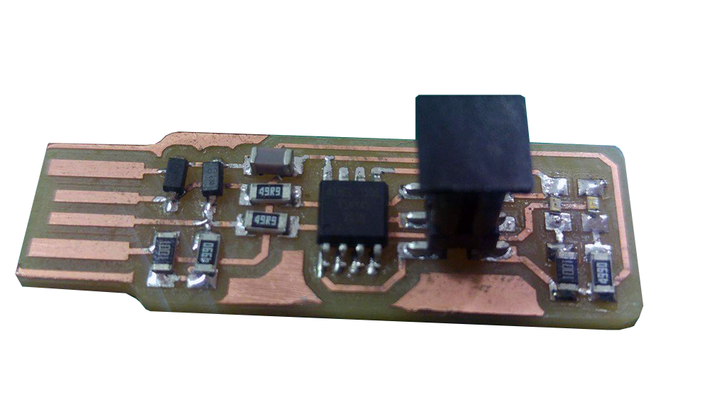
Here is the complete PCB
DOWNLOAD FILES
TRACES.png TRACES.rml
CUT.png CUT.rml
1.1 Milling and Cutting, Round Number 2
As first result, soldering where not so good and I needed to try again the process. I retried to produce another PCB by milling and welding component in order to improve my soldering skills, paying attention to put the right quantity of tin on each pad. The outcome should be a shiny and glossy soldering pad.

2. Programming the FABISP
Let's come into programming. After soldering all the components, I plugged my FabISP into a pc, which OS is Ubuntu, through a USB programmer (ATMEL ICE). The device has been detected! Then, I opened the terminal and start to follow the tutorial.
I typed the command sudo apt-get install avrdude gcc-avr avr-libc make and downloaded the firmware fts_firmware_bdm_v1, then unzipped the files. Then I typed "ls" from the terminal to check if the files were actually in the folder.With the command make, I have generated the .hex files for the ATTiny. Further, I gave the command "make flash", programming a flash memory with the contents of the .hex file.

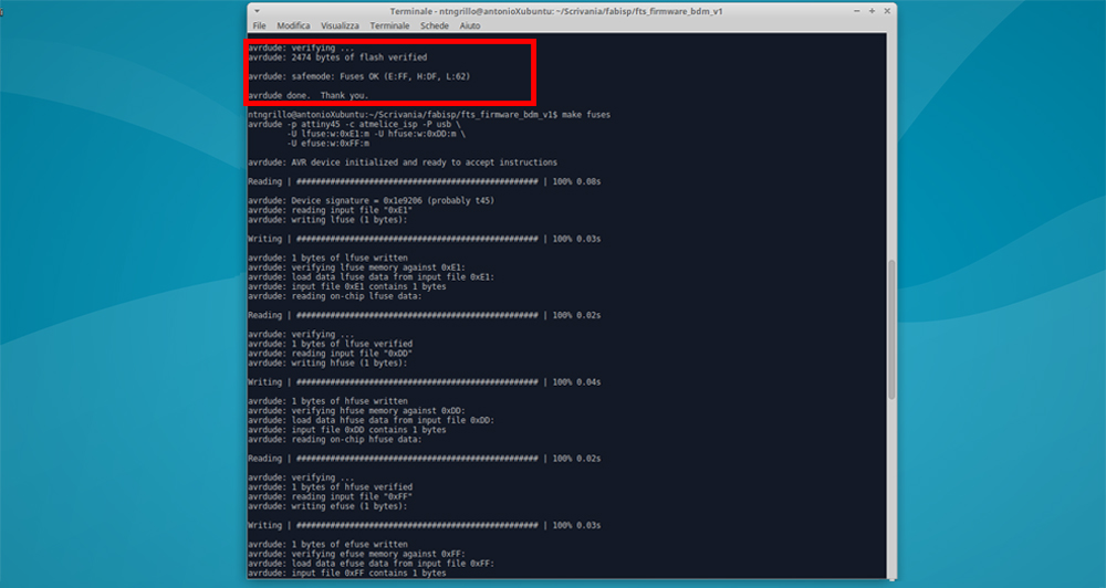
To check the USB functionality, I have followed the instructions of the tutorial, which says: "Type lsusb in the terminal, which will list USB devices. If you see a "Multiple Vendors USBtiny" device, it worked!". Well, I dit it an it worked! Another step forward.

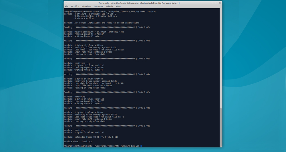
Last step is the rstdisbl command, which was successfull. After that I removed the solder from the jumper.
IMPORTANT To avoid techical issues to the hardware, it is highly recommended to cover the board with some insulating glue to prevent copper oxidation.