Program your Machine

After improving the slider's upper part design, we started to figure out how to make the Nema17 working. Our first approach was to connect a A4988 driver to ARDUINO UNO and send some sketch. There are plenty of tutorials on the website, such as this one."
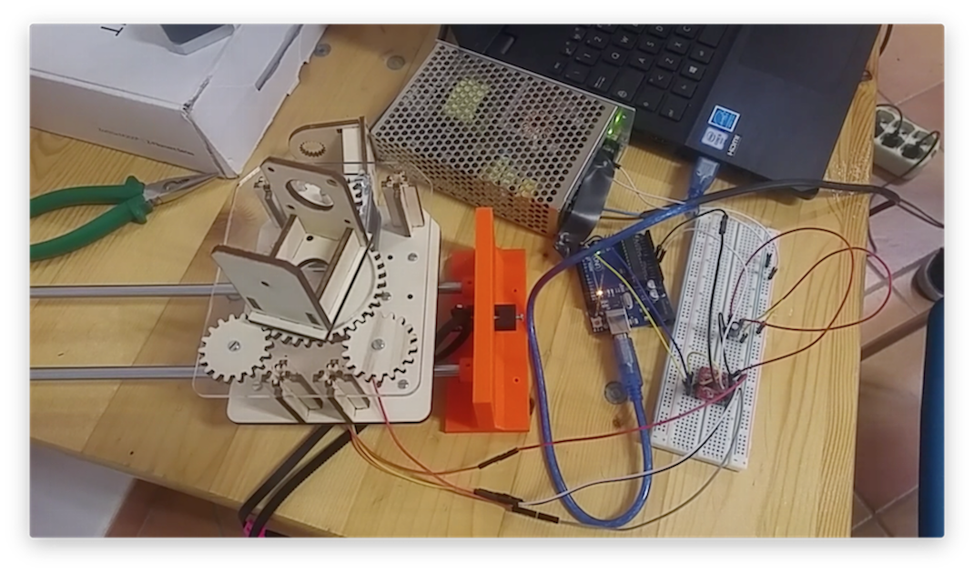
So we started to assemble the harwdware and connect arduino to the drivers and the nema, usign a breadboard. The scheme I used is, more or less, the following:

We started with one driver and one Nema, then we added an extra stepper motor. This video also helped a lot, since explaining all the correct steps.
After this first try, I understood that there were some problems which had to be fixed. First of all, the 4-gears mechanism was not smooth and too noisy. For this reason I improved the holes in the main gear. By so doing, the screw went more inside, avoiding the contact with the plexiglass surface.

Then, I started to model a new adjustable gear which will be 3d printed. I realized that wood is not recommended for gears, better use plexiglass or PLA/ABS. Once decided about design improvements, I went forward. My aim was to connect the GRBL shield and arduino in order to have a preassembled board with 3 stepper motor drivers slots.
In our fablab we have this one: CNC shield.

On the Git GRBL webpage, it is possible to understand what is GRBL: "Grbl is a free, open source, high performance software for controlling the motion of machines that move, that make things, or that make things move, and will run on a straight Arduino."
An important guide for me is this one, which explains step by step how to connect the hardware and make grbl running into your arduino board. I want to highlight some important rules of this tutorial, since useful for beginners like me:
1. NEVER PLUG OR UNPLUG COMPONENTS WHEN THEY ARE POWERED
2. CAREFULLY OBSERVE VOLTAGE AND POLARITIES. DO NOT CONNECT THE POWER BACKWARDS
3. DO NOT FORCE THE CURRENT SETTING POTENTIOMETERS BEYOND THEIR 270 DEGREE ROTATION LIMIT. THEY WILL BREAK AND THAT AXIS WILL STOP WORKING
4. DISCONNECT USB PLUG FROM USB POWERED ARDUINO BOARDS
I followed some tutorials on the internet. For making GRBL working on the arduino uno, we need to flash the arduino board before. This video shows very easy how to do it. The issue I had was about the USB port. Due to an USB hub, Arduino IDE gave me some problems to recognize correctly the port. So I removed the usb hub and plugged the USB from Arduino Uno directly to my Macbook. There are different ways to flash Arduino with GBRL. For example some other tutorial suggests to upload GBRL software to Arduino Hardware by downloading the GBRL .hex and upload it through a HexUploader. For Mac, HexUploader, for windows xloader.
I decided to follow this tutorial, since more fast to do, just using Arduino IDE.
All files and instructions step by step are available also here.
Using ugs
After flashing Arduino UNO with gbrl through Arduino IDE, I connected all the hardware with a power supply, using 24V for the stepper motors. But before doing it I
checked again the correct value with a multimeter on the potentiometers. Correct value are around 0.40-0.55 for a Nema 17.
I have downloaded UGS, from here. You can open the zip file and run the .jar application.
After that you have to set the correct port, as showed in the following picture.

Baud, which is the number of symbols transmitted, will be set on 115200. After that, it is possible to open the port in order to send GCode.

Here is the first test we did with GRBL and UGS. A very important issue was that the Z axis has to be fixed in order to keep the position. As a matter of fact, once we started to move the camera, the stepper was rotating and then not holding position, makeing the camera falling down. To fix this issue I have applied a solution I found on a forum: "Step idle delay($2) should have been set higher. Setting it to 255 keeps grbl from idling the steppers. Downside they get hot, upside they stay put!".