Now Let's Talk!
Model: Schematic & Board
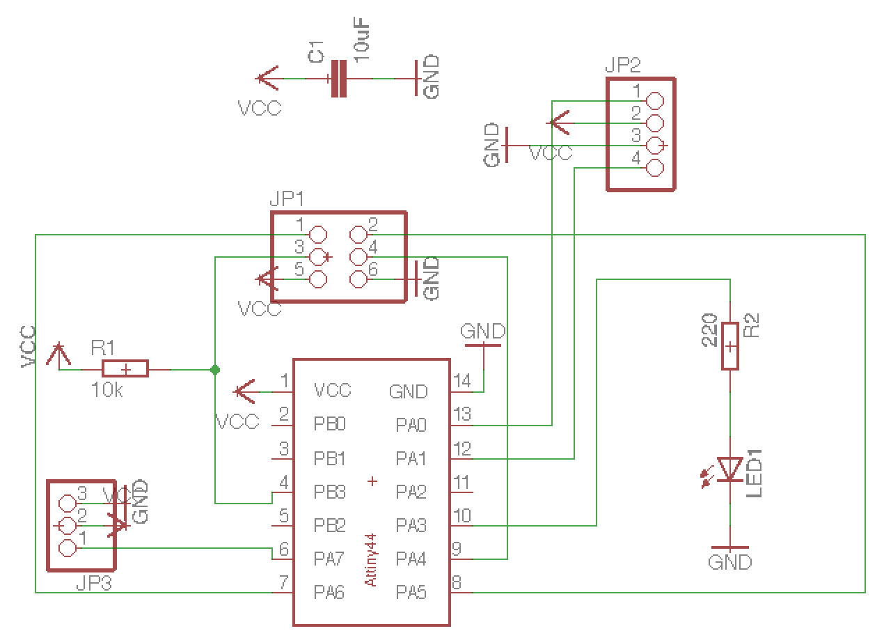
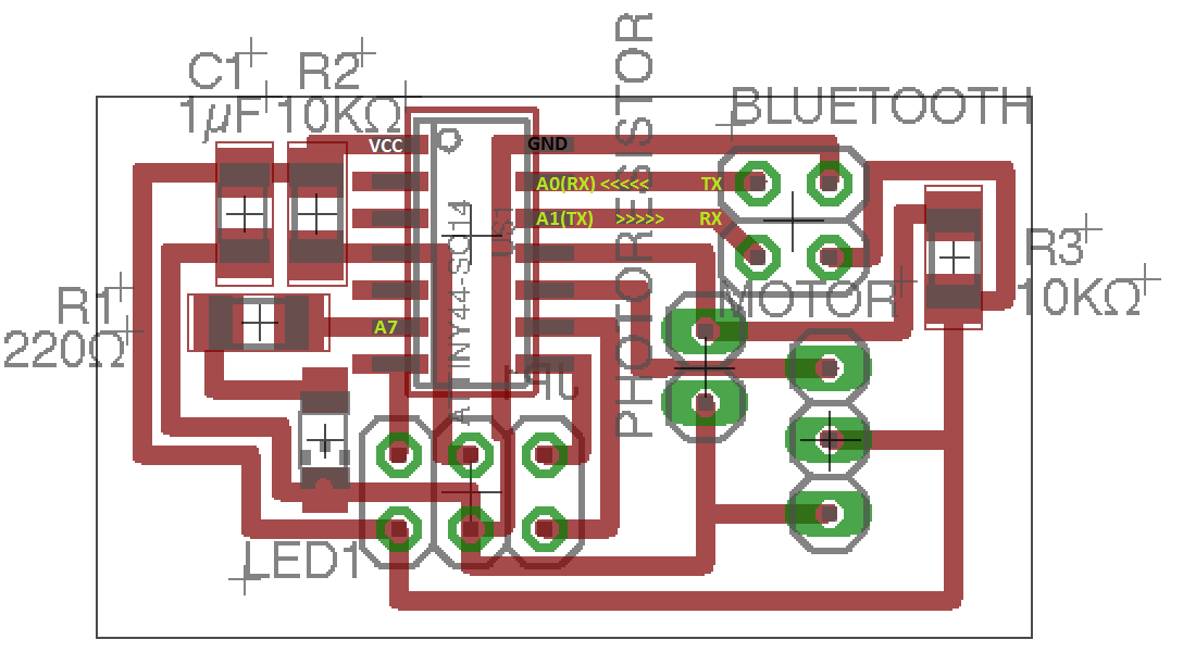
So I simply modified schematic from previous exercise(Inpug & Output design) by adding 1x4 pinheader for connecting bluetooth module
to my PCB, and removed photoresistor from the scheme.
Since last time I made a mistake by connecting motor parts to PB(binary input)of the sensor than
PA(Analog input, what it needs to be done), I kept 1x3 Pinheader this time.
This time, it went quite easy :D
Here are images of my schematic and board.

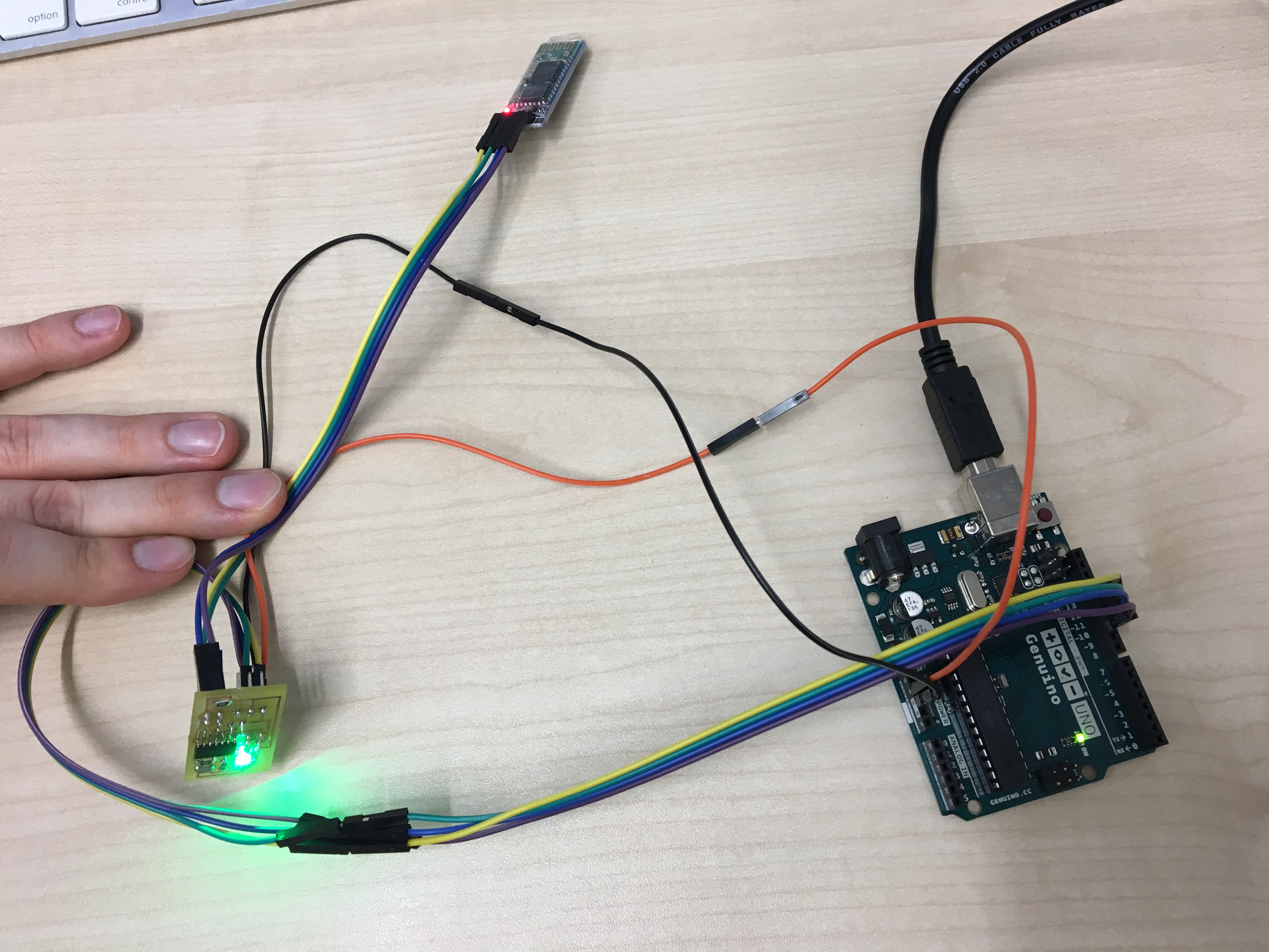
I used an HC-06 bluetooth module (DataSheet). The HC-06 bluetooth module was very easy to use. Once the wiring was correctly done everyhing you could connect to the bluetooth module with any other bluetooht capable device and send characters which are then forwarded to the attiny on the board. The whole setup was very convenient and way easier than I expected when I first thought about using bluetooth protocoll.
Wiring
you can find the datasheet of bluetooth modules from here.
when the board is connected right to the bluetooth modules, your bluetooth chips will start blinking. Then half thing is done. The bluetooth module uses a serial communication and thus it is important to focus on how the RX and TX pins need to be connected. Sparkfun has a good article on how this serial communication works. The serial communication protocol sends bits in a timed interval (the baud rate). The send bits compose a frame of bits which contains the data, start, synchronization, and stop bits. Sender and receiver can write and read those frames to the serial communication channel. The bits beside the data bits are used for synchronization and error checking (parity bits).
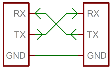
An important part of the wiring for the serial communication is that there are two connections called RX and TX. RX is the Receiver and TX the transmitter channel of each device. It is therfore to not connect the RX connection of device A to the RX connection of device B because then both receiving channels would be connected. Therefore keep in minde to connect the sending connection TX of device A to the receiving connection RX of device B.

Programming
Here I import set the serial communication, and I tell my pcb module to turn led on if it gets '1' and off if it gets '0' over bluetooth network. It is important to mention that I used the SoftwareSerial Library by arduino since the the attiny44 does not support a serial communication by it's own. The SoftwareSerial library simulates the hardware serial communication via software and thus enables the attiny44 to communicate with the bluetooth module using serial communication.
//import library for serial comunication
#include < SoftwareSerial.h >

const int rx = 0;
const int tx = 1;
const int LED = 8;
SoftwareSerial mySerial(rx,tx);

void setup() {
 mySerial.begin(9600);
pinMode(LED, OUTPUT);
}

//processing incoming chars
void loop() {
while(mySerial.available() > 0) {
char receivedChar = mySerial.read();
int intReceivedChar = (int)receivedChar;

if (intReceivedChar == 48)
{
digitalWrite(LED, LOW);
}

if (intReceivedChar == 49)
{
digitalWrite(LED, HIGH);
}
}

}
Below are results from the assignment.