Electronics & Programming
Please see work in detail in weekly assignments :
Input , Output and
Networking
In this page I make a recap of how it should work, what are the problems and how they are solved or what remain to be solved.
1. Planning Work flow
The Plan :
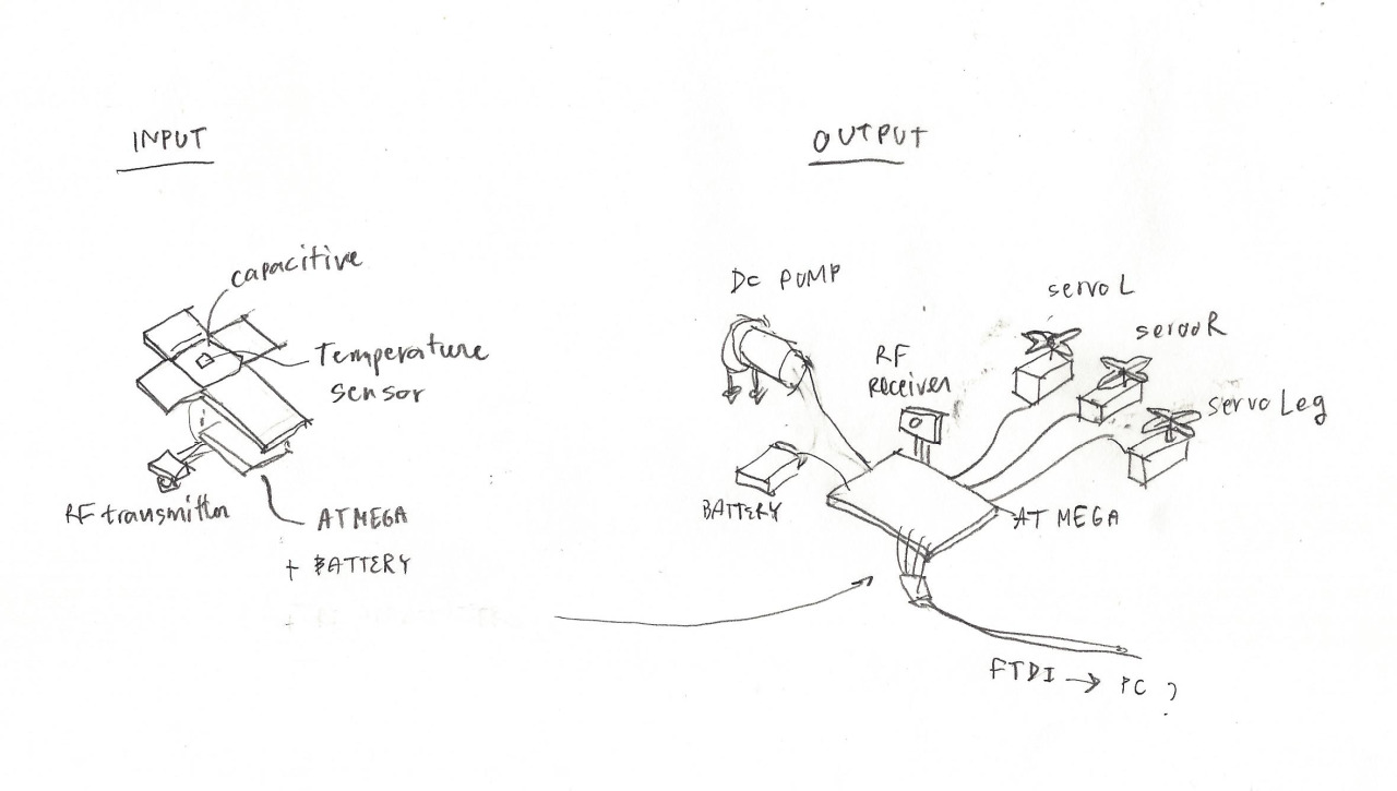
INPUT Programming workflow
1. start
input : temperature makes sudden change (some one touches it)

2.draw
input : use temperature value as random seed to create more random numbers
use time stamp as random seed
communication : RF transmitter

3.stop
input : temperature makes sudden change (some one leaves it)
OUTPUT Programming Workflow
Elemennts :
- servo arm L,R
- servo leg
- dc pump

States :
1.draw
- dc pump starts
- servo arms move
(L,R); (L,R)...


2. stop
- dc pump stops
- servo arms close
()
- servo leg closes and then open the book
2. PROBLEMS & SOLUTIONS
1) RF Communication does not work
UNSOLVED : I Couldn't figure out yet what went wrong with RF.
So the plan is to keep everything connected to pc and send inputs via Serial
2) Temperature value changes too slow, I can not identify the moment when it is touched.
On the other hand, when it is not touched, the value changes too much. So, with temperature sensor it's not possible to identify starting point of interaction
SOLVED : I added a capacitive sensing to send activation signal
3) Servo motor reset their default position everytime it receives power. This can create crashes between arms
UNSOLVED : (but can live with it) for now there's a small procedure
for avery starting time :
- togliere le braccia
- fare partire un giro seza braccia
- quando finisce il giro la gamba si mette al suo posto.
adesso puoi fare partire normalmente.
4) Interference mystery ? From problem point 1, I test with this set :
INPUT : capacitive , LED for debugging, push button for debugging
OUTPUT : dc
And there a strange thing happened. While push button can activate a dc at analog value less than 255, Capacitive can not.
In the same situation the LED is on, meaning that it is TRUE but dc motor works only at 255...
UNSOLVED
5) Interference mystery ?? When all 4 motors are on the same circuit, the communication is jammed.
Particularly when any external battery is connected (both 5 and 9v),the servos work badly.
They move mistakenly and in wrong moment. It disturb event the logic of all the servos:
when debugging, the LED works but servos do not.
My guess is that external battery did create problem 4.
UNSOLVED : so sadly I have to seperate Input and Output circuit... And since RF does not working either
now the output works with push button activation and then it uses random numbers for movement..