
Week 8
Embedded programming (Mar 16)
Assignment:
read a microcontroller data sheetprogram your board to do something, with as many different programming languages and programming environments as possible
extra credit, try other architecture, other families. e.s. PSoC
- Note from lecture
- flexture / curving
- bug was a real bug !
- AVR
- datasheet is the reality

- arduino uses C language
- GCC compiler translates C to hex
- FTDI cable converts serial to usb
- IDE compile, write,/... in a visual way
- PSoC windows only
- ARM processor architecture. more general purposes, complex libraries.
disappointing for realtime hardware performance. can get to a much more complex soft/hardware e.x.webcam

- velocity comparison : C million cycles per sec.
- codebender https://codebender.cc/
- Local lecture
- fonte di data sheet  octopart
compilatore prende file in c, transforma in hex. make program caric sulla scheda
invece con Arduino (ambiente di sviluppo) verifica = make hex. upload = make program
firmware = software del hardware
Arduino :
	porte digitale - zero o voltaggio
	analogici da zero a 5 volt (caso Arduino : 10 bit, da 0 a 1023)
	pwm : output analogico simulato. modulazione a picchi
	DAC
	SPI protocollo di communicazione.. MISO manda. MOSI riceve. SCL metronomo. SS da' il turno
	I2C (Wire) protocollo ch eimplica 2 piedini. SDA : communicazione , SCL :
I2C e' molto usata con i sensori
	Serial : RX riceve, TX trasmette. debug. (pin 0,1 ) quindi non attacca mai
	Arduino ha ISPtiny e hello board dentro. si communicano con Serial

RTOs
Links : Attiny44 summary datasheet
Satshakit


siringhe
01_Arduino IDE
Follow this tutorial,
1. In Arduino IDE, go to File > Preferences then copy & paste this Board library
link (credit :
Francesco)

2. Tools > Board > Board Manager .. find attiny and install it. Now you can select it from from the list

3. select the right processor Tools > Processor > ATtiny44 and selecet the right clock Tools > Clock > 20 MHz (external)

4. lastly, select our programmer and we are set to go

5. I connected my FabISP, hello board like this. My LED on Attiny44 is on pin 6 so it corresponds to Arduino pin 7

Check pin numbers with the schematic


6. I open Blink example an edit the pin number. verify, then upload. The code uploaded but the timing is wrong !
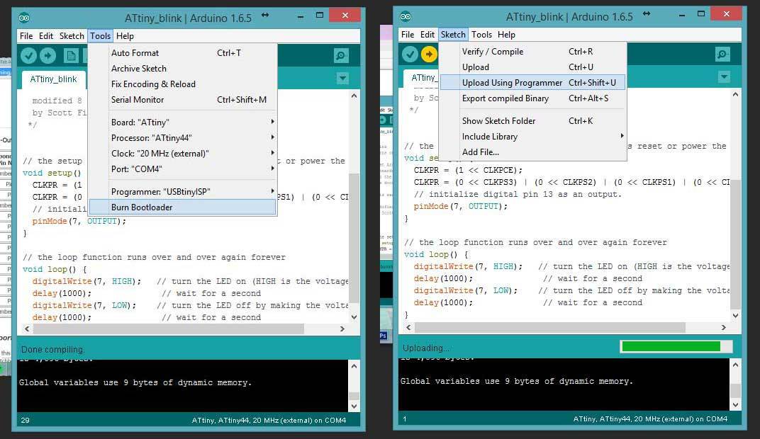
7. Blink the LED With a super help from our classmate Andrea, he suggested to add a few lines in the code to solve fuse timing problem. further references : http://fab.cba.mit.edu/classes/863.15/doc/tutorials/programming/clock.html http://fabacademy.org/archives/2015/doc/fuses.html Here is my code :
void setup() {
  CLKPR = (1 << CLKPCE);
  CLKPR = (0 << CLKPS3) | (0 << CLKPS2) | (0 << CLKPS1) | (0 << CLKPS0);
  //
  pinMode(7, OUTPUT);
}

//
void loop() {
  digitalWrite(7, HIGH);   // turn the LED on (HIGH is the voltage level)
  delay(1000);              // wait for a second
  digitalWrite(7, LOW);    // turn the LED off by making the voltage LOW
  delay(1000);              // wait for a second
}
8.Read the push button blinking LED works good. nex step is working with the push button. My button is on pin 10 so it's pin 3 (Analog input3) on Arduino. Here's my code :
#includeSoftwareSerial mySerial(0, 1); void setup() { CLKPR = (1 << CLKPCE); CLKPR = (0 << CLKPS3) | (0 << CLKPS2) | (0 << CLKPS1) | (0 << CLKPS0); mySerial.begin(9600); } void loop() { int sensorValue = analogRead(A3); // print out the value you read: mySerial.println(sensorValue); delay(1); }
It works ! From serial monitor, value 0 is when I pressed the button :

9.LED + Button, without delay I want the LED to blink faster when the button is pushed. Delay function in Arduino is good for a quick, rough programming but it gives problem with timing so it's always better to avoid using it. References : Millis , BlinkWithoutDelay, AvoidDelay
Here's the code :
#includeSoftwareSerial mySerial(0, 1); const int ledPin = 7; int ledState = LOW; unsigned long previousMillis = 0; // the setup function runs once when you press reset or power the board void setup() { CLKPR = (1 << CLKPCE); CLKPR = (0 << CLKPS3) | (0 << CLKPS2) | (0 << CLKPS1) | (0 << CLKPS0); mySerial.begin(9600); pinMode (ledPin, OUTPUT); } void loop() { int sensorValue = digitalRead(A3); // print out the value you read: mySerial.println(sensorValue); delay(1); if (sensorValue == LOW ) { unsigned long currentMillis = millis(); if (currentMillis - previousMillis >= 100) { // save the last time you blinked the LED previousMillis = currentMillis; // if the LED is off turn it on and vice-versa: if (ledState == LOW) { ledState = HIGH; } else { ledState = LOW; } // set the LED with the ledState of the variable: digitalWrite(ledPin, ledState); } } else { unsigned long currentMillis = millis(); if (currentMillis - previousMillis >= 1000) { // save the last time you blinked the LED previousMillis = currentMillis; // if the LED is off turn it on and vice-versa: if (ledState == LOW) { ledState = HIGH; } else { ledState = LOW; } // set the LED with the ledState of the variable: digitalWrite(ledPin, ledState); } } }
TX pin 13 (PA0) RX pin 12 (PA1)
<< previous | next >>