Week 5
3D Scanning and Printing(Feb 24)
Assignment:
* test the design rules for your printer(s) (group project) * design and 3D print an object (small, few cm) that could not be made subtractively * 3D scan an object (and optionally print it) (extra credit: make your own scanner)- Note from lecture
- 3d printing = ability to fabricate part you can not get with classic tools
- additively
- constraints : material PLA is easy to use, "carbon negative",
resolution : angles, minimum thickness, sharpness. respect or you;ll get crash
- carbon

- assmbler / disassembler ??
- RepRap - machine that makes machines
- Sindoh - most sofisticated for entry level machine, like a high-end one
- Formlabs- hig-res, print wax also
- MTM
- shapeways

- STL - a stupid format, a list of triangles. it doesnt say units.
easy to write a script
- dont use DXF

Scanning
- photogrammetry
- speckle - good as starting pointer
- Modelling mechanical part
02_3D modelling
Beginning from reference I found, seems like the mechanicsm I want is similar to windscreen wipers
Even though these Inverse Parallelogram Mechanism look pretty interesting let's now focus on the wipers.
Since there're many gears I'll try to use Rhino script Rayflectar to make them
It took me a while to understand how to use the plugin. Now my technique is : make the circle pitch, then choose pith number which, from what I understand, is the tooth size. then choose to maintain pitch circle. done.
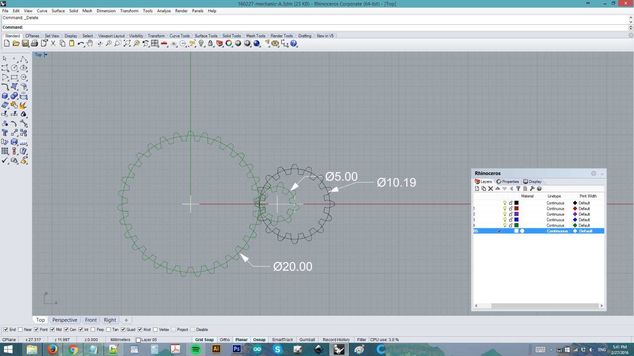

I try to make it as small as possible.. here's how it is so far
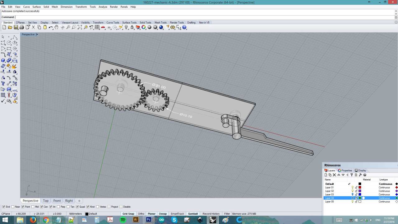
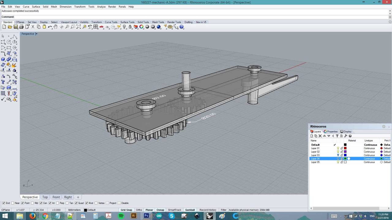
but then I'm stuck with the last part.. I don't know how to calculate the shape ! I tried rotating thw gear and the wiper but can't figure out still

So I left it there and find other 3d models to print....
01_Scanning with Agisoft Photoscan
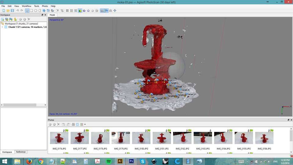
0.intro : I did not make success until after 20 tries. This page is updated 2 weeks after the assignment.
Here is one of the failure.. in this case I use wrong object, the coffee machine is too reflective.
Here are some usefule notes:
 Do
- Always feed the program with photos where at least 60% of the photo is on
focus.
- Once markers are recognized, check on every photos if the markers are present.
Manually add recognized markers for better photo alignment
- Perform Close-up photos only for small details
 -If you need a photo with less than 60% of the photo on focus, mask out the out
of focus part of the image.
- If you are photographing a small object and you get too much background
information per photo mask out the unwanted background information from
the photos in order to feed the program more object info and les background
info, this will decrease the alignment time considerably.
- Always use high contrast between the object and the background
Don’t
- Feed the program photos with too many photos or just a few, a good rule of
thumb it’s to give the program photos with at least 60% overlapping.
- Color correct the photos in an editing software (i.e. Photoshop), may cause
alignment problems, because depending on the lighting system and camera,
some of the photos may have slightly different tones or lighting values.
- Use reflective object as model
1. I took the photos outdoor, in a cloudy day. the markers
are 25% scaled from original size. I took 2 shots for every position, one from above and one from below. total 50 photos taken

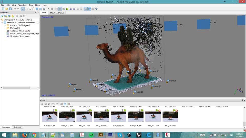
2. In Agisoft Photoscan
, import all photos, go to Tools > detect markers. The software do not recognize markers from below so I
manually added them, 3 or 4 for each pictures.

3. Then Process > align photos


4. Make dense cloud. I use high, disable depth
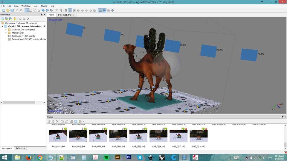
5. Make mesh from dense cloud. I use medium.
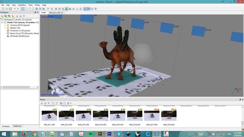
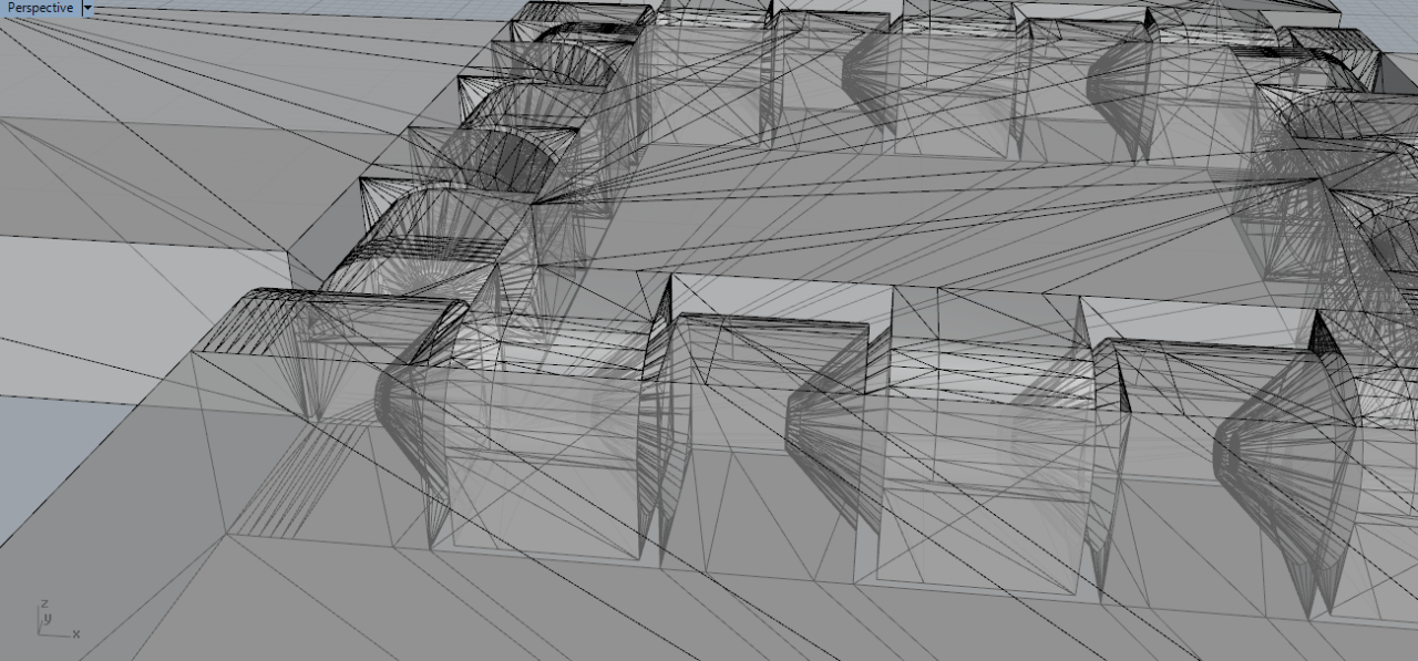
6. I try to create different dense cloud, medium and high. here is the result as seen in Rhino
 Left:Medium Right:High
7. I choose the higher resolution one.Even if there's more to clean but I believe I can manage that with
a mesh cleaning program. I tried without succeed with Rhino so I changed to
Meshmixer

8. First thing to do is to delete unwanted debris. Go to Edit > Seperate Shells then in the Object Window,
select unwanted mesh and delete them.

9. Edit > Plane cut

10. So now that we have a pretty clean mesh, I can refine the surface a little bit. Go to Edit > Make Solid and play with
Solid Accuracy and Mesh Density values. Once done, export the file in stl

02_Printing with Wasp Delta
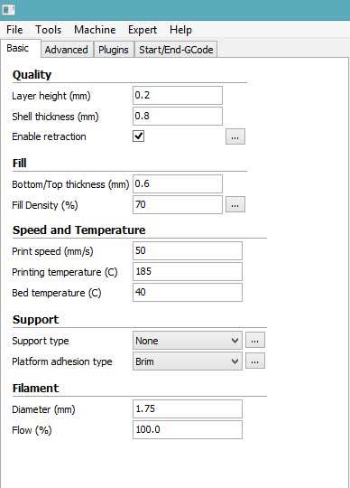
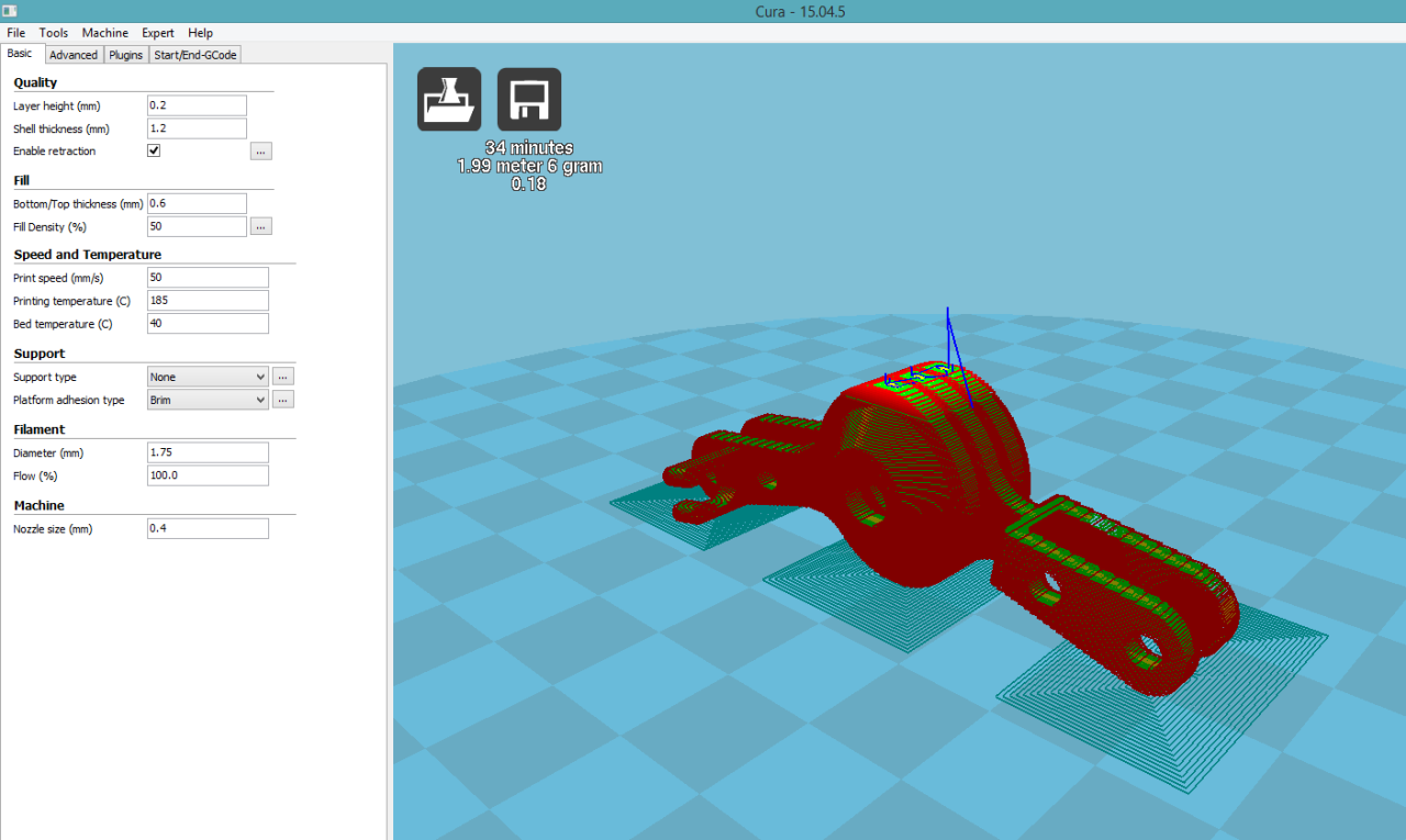
1. Open the stl file in Cura. I add the Support : Support type :none , Platfrom adhesion type : Brim

2. Since I do not want to add the support, the printing will not be perfect.
The tail might not be printed and probably the camel's belly will fall down.

3. Printing

4. Here's the outcome. Doesn't look bad !

5. Camel family : )

- >> tips on printing from this article
for example, this article has some tips and examples


- Using Grasshopper
Modelling with Grasshopper
Also I want to try printing complicated shapes So, I decide it's time to learn Grasshopper
01 - Interface Basics from Rhino Tutorials on Vimeo.
Notes on Grasshopper
- input on the left, output on the right
- in runs inside of Rhino, what is made in Grasshopper can not be modified in Rhino
- hold ctrl to delete connections (the wire cursor will turn red), hold shift to add
more than one wire. hold shift+ctrl to move several connections
- double-click and type to call any funciton
- double-click and type min value < default value < max value to get a slider
- press Space, right-click or middle-click to able/disable preview
- "bake" is to ttransform Grasshopper object to Rhino
- press ctrl+alt to call for info. click on an object to see where there is on tool bar
Sadly I do not have enough time to continue. I'll continue study after Fab Academy
03_Design for a non substrative machine
2/8/2016 : This is an added element made for final project.
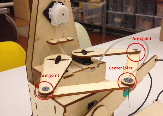
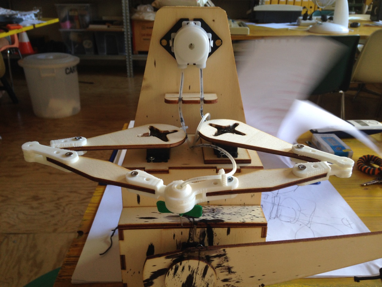
For the final project, the arms of the machine are moved by 2 servo motors. Originally I printed these simple joints
0. Getting inspired by Hingebox
What is done there looks fit for my use.:
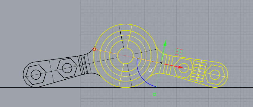
1. Making first tooth of the center joint
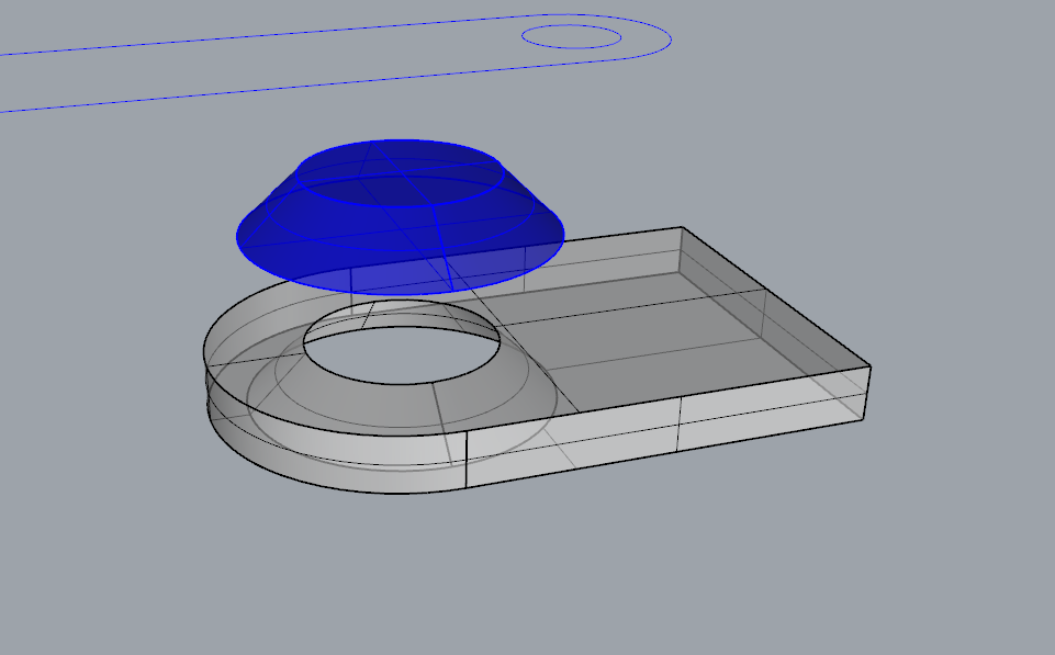
2. Copy for other joint teeth. I keep distance of 1 mm between each tooth
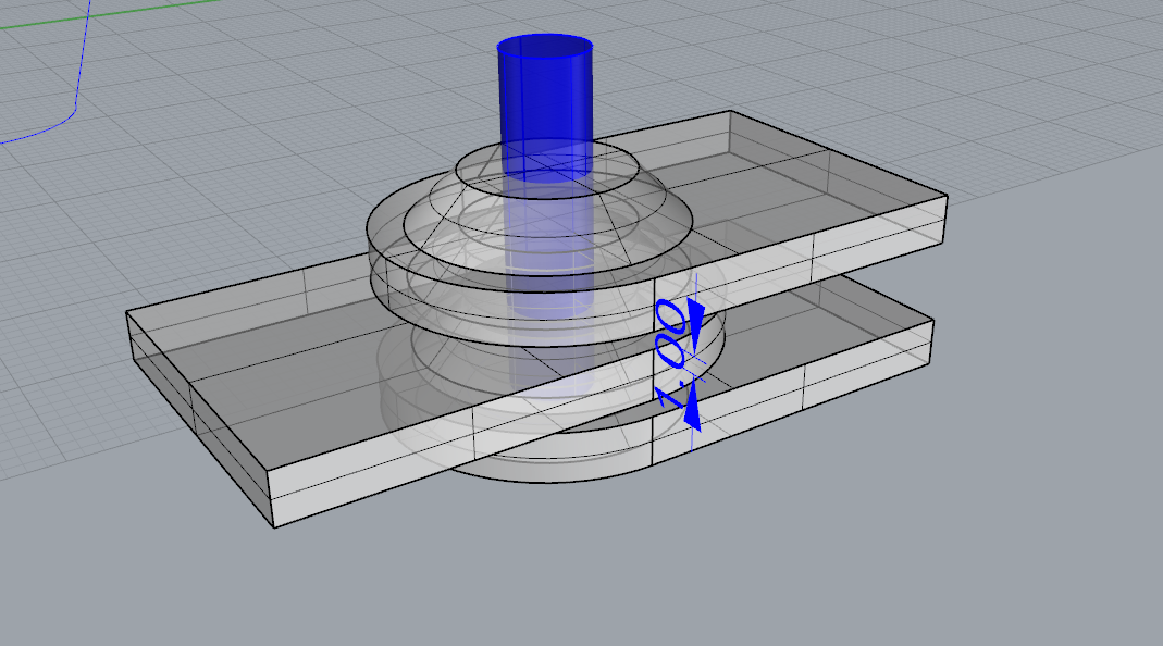
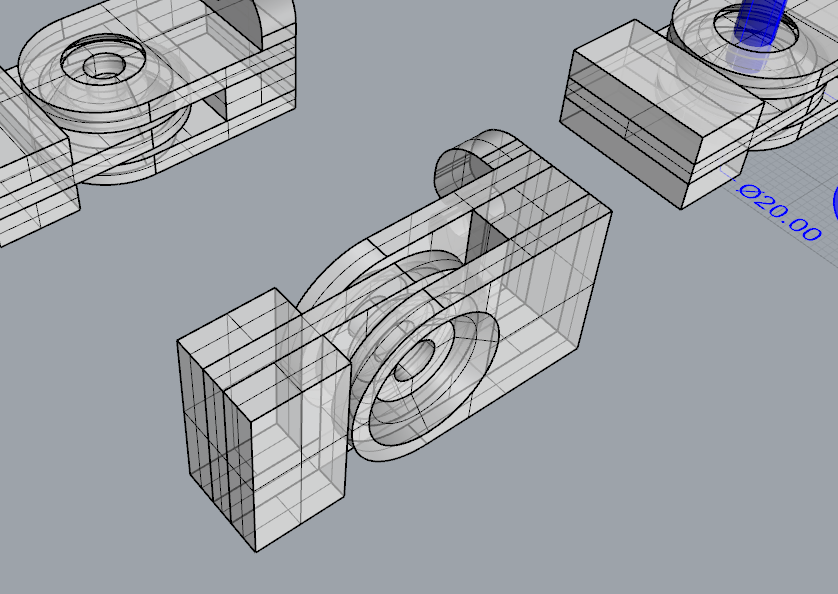
3. Then I added also the part that hold the tube to test. When the model is complete I rotate it in the correct direction for printing.
Since there are gaps between teeth, the model has to be printed from aside.
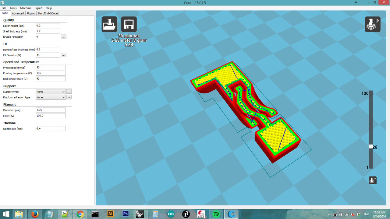
4. Import the stl file into Cura and set the machine parameters.

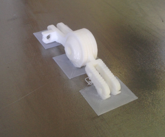
5. The printed came out quite good. The holding part for tube is a bit mess but the teeth look fine.
 The 1mm gap is printed perfectly, I did not need to manually clean it. But probably I can try a less wide gap ?
 Main problem is with this model is that it permits only max 90 degrees rotation
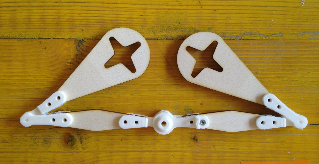
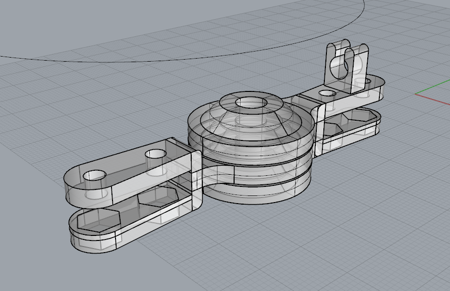
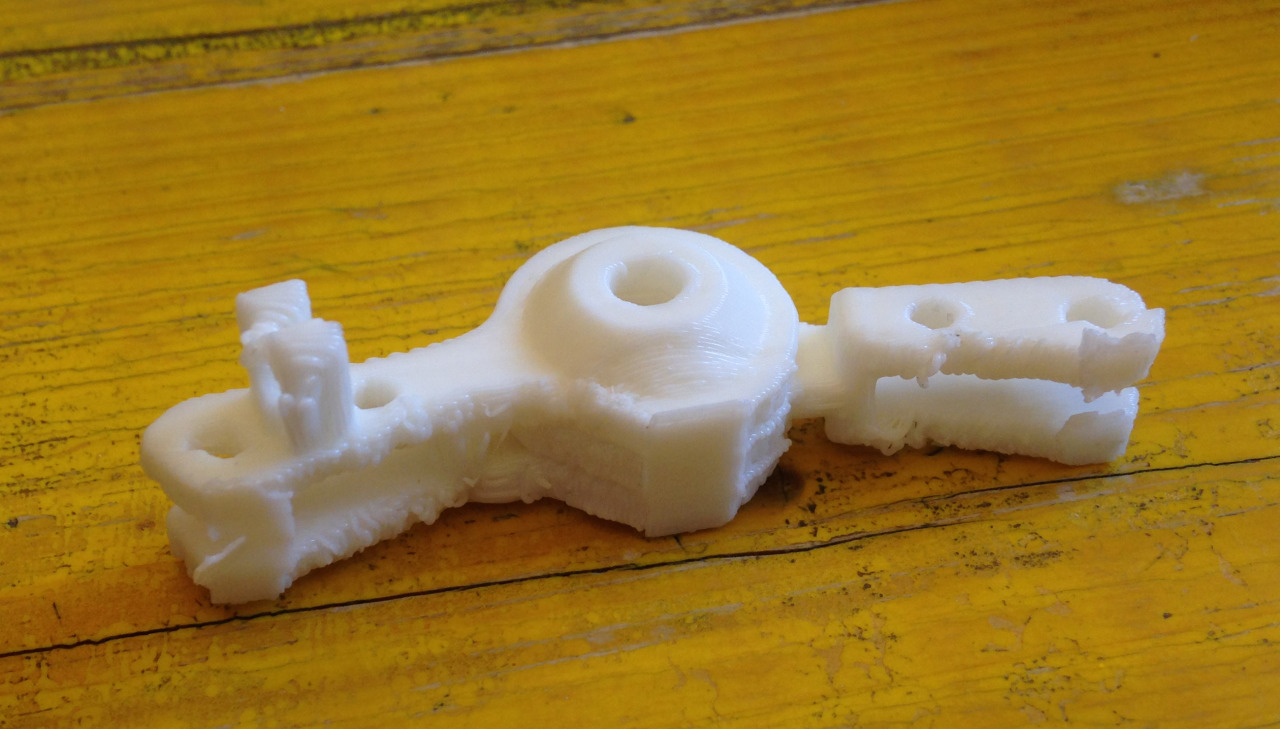
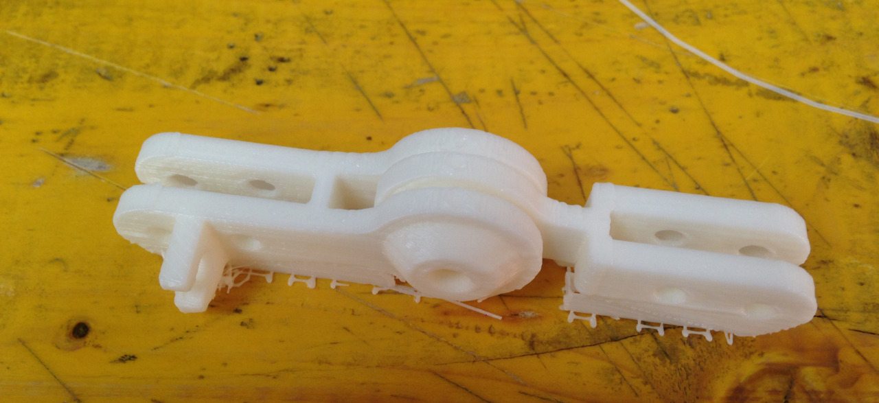
6. After many test here's what I think could work. The red pieces simulate the laser-cut wood pieces of the arm.
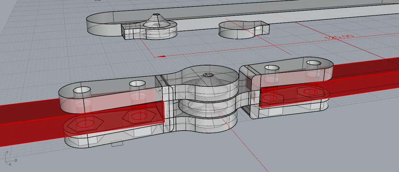 This is the center joint. I lower the gap to 0.3 mm for testing
7. To print the center joint is quite tricky since the legs have to be small to permit more rotation angle.
I rotate the model to gave more touching point at base.
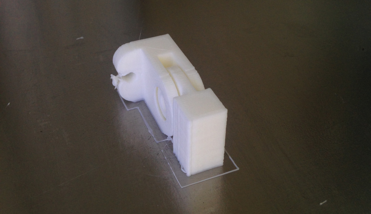
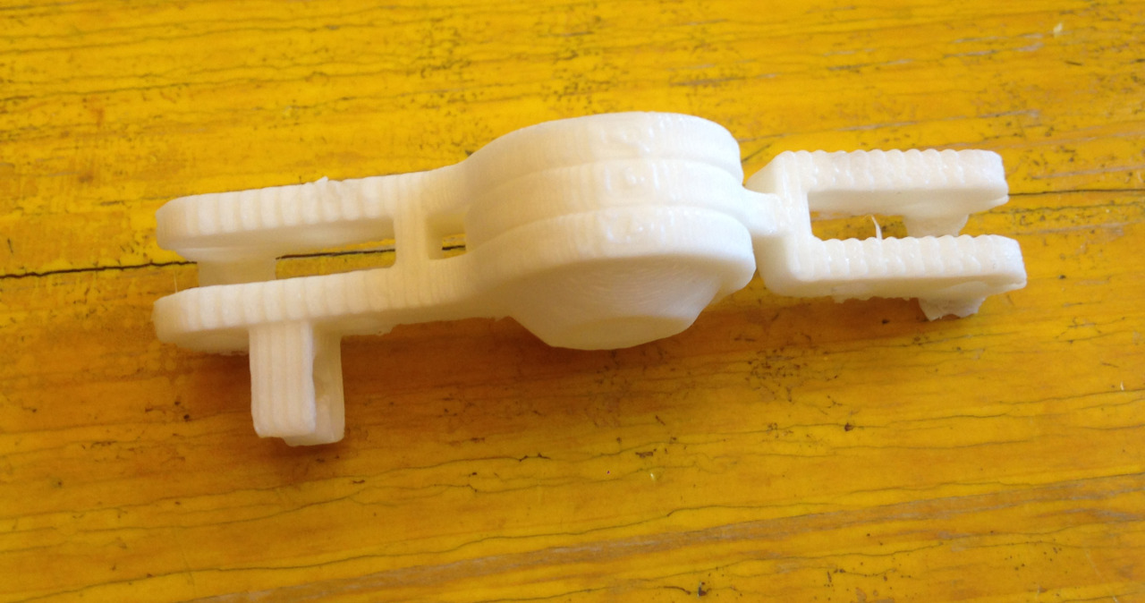
8.First test is to print without support but with brim.
9. Printed. The result is quite a mess !
 Without support the print can not stay.. so it lost all the precision..
 And 0.3 mm gaps is apparently too narrow..
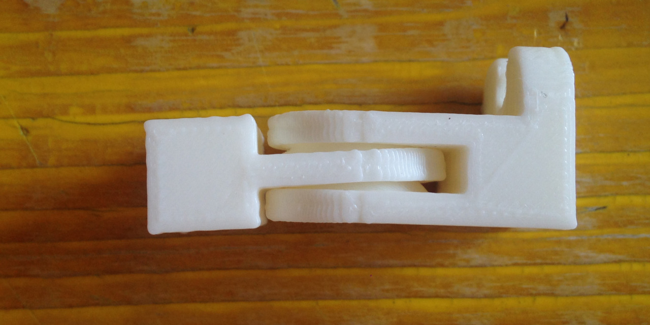
10. This time the gap is 0.6mm. The print is with vertical support turns out a lot better but the gap is still too narrow.
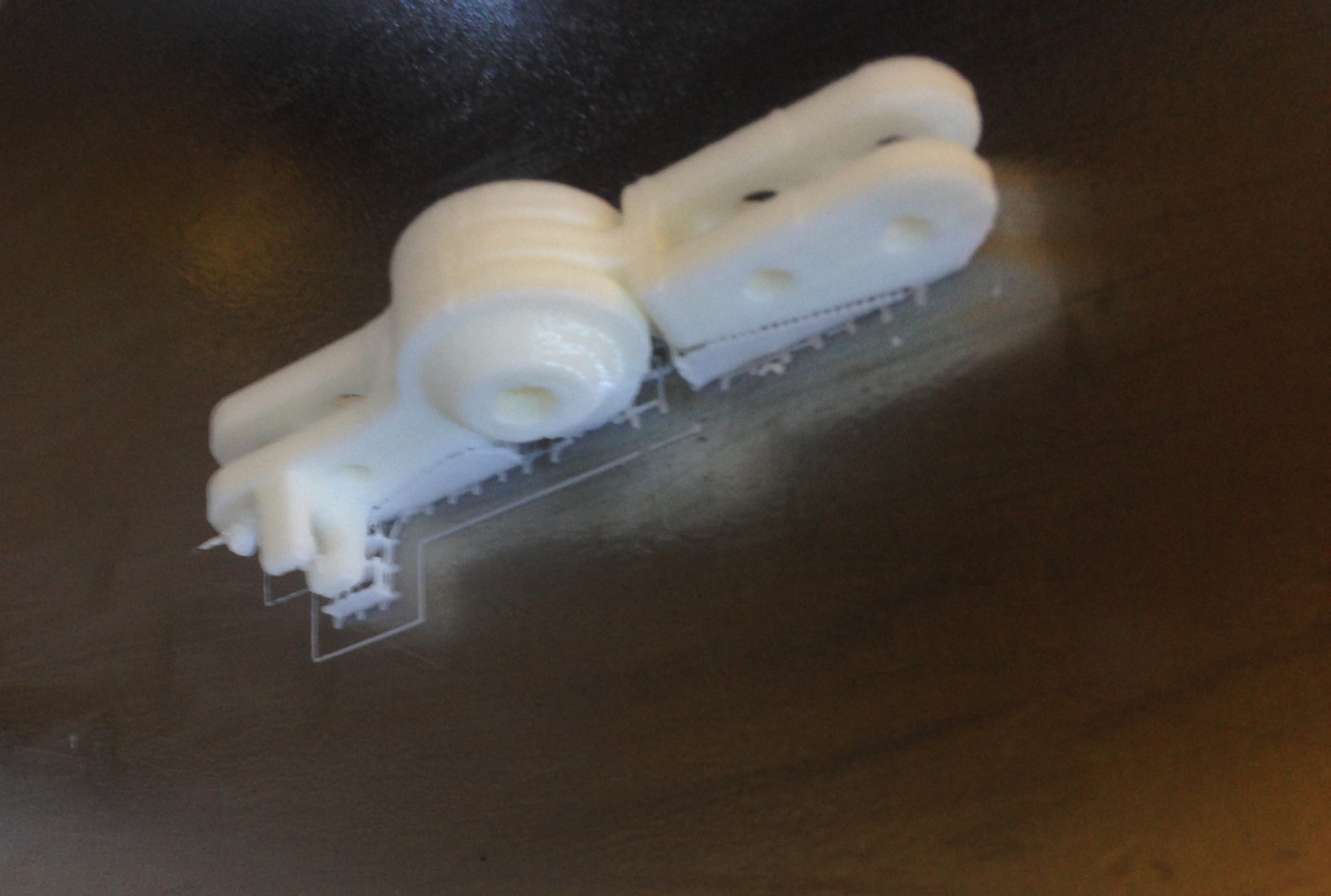 The precision is good. the bolt fits well.
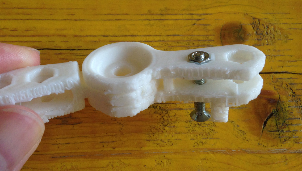
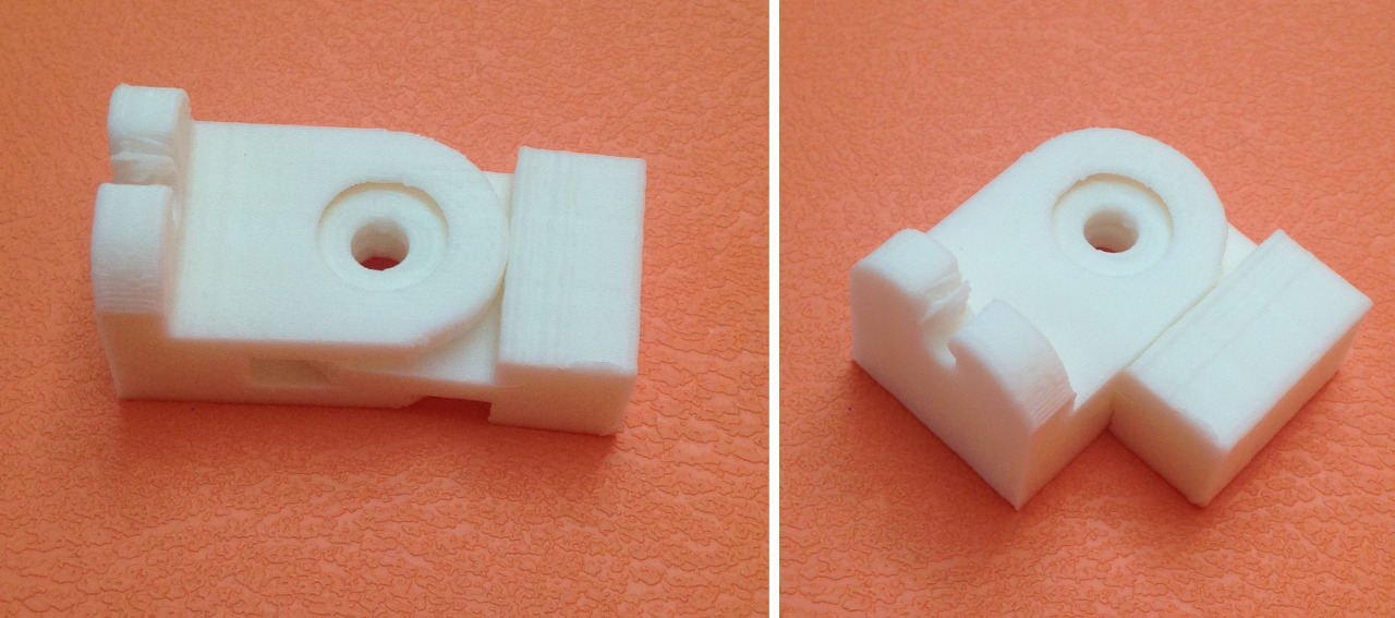
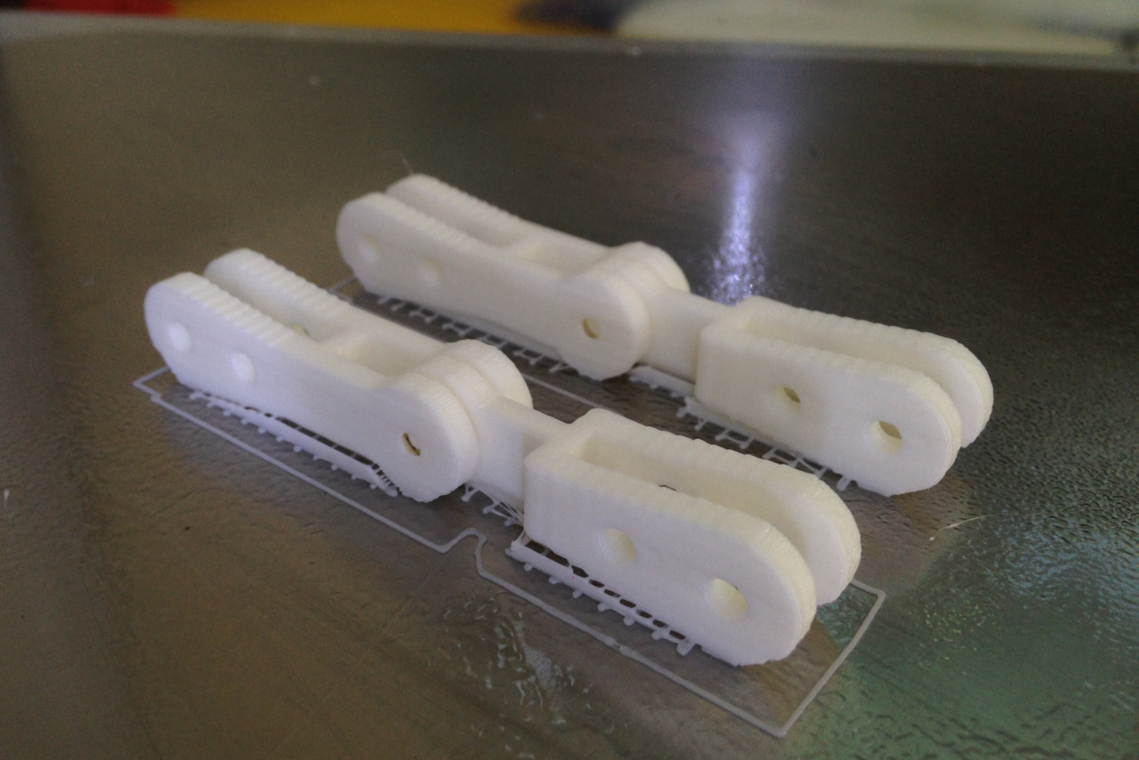
11. So I adjust the gap again, returning to 1mm and it looks good
12. The other 2 smaller joints
 Rough cleaning the support
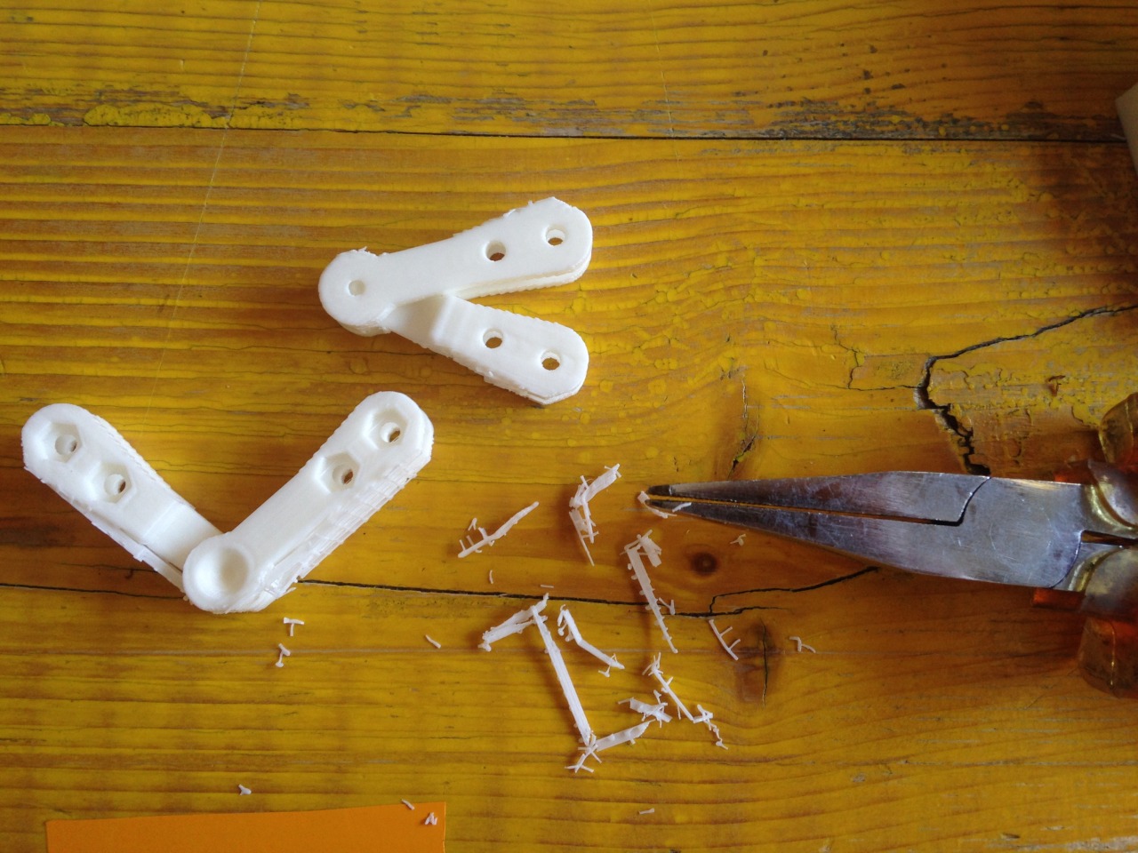
13. All the prints
 Assembled with the structure
Download files camel files :obj, stl, gcode markers 25% pdf machine hinges stl | 3dm(Rhino5) << previous | next >>