Week Fiveteen
This weeks assignments
- Design a PCB that can connect two microcontrollers togeather.
- Mill it out.
Networking
- Read the datasheet carefully, be sure which pins need to be connected and which pins dont.
- When going from the schematic to the board itself, sometimes the pinheads don't align correctly, backtrack on the board.
- It might be a good idea to try and develop a system on which pinhead is which, maybe make a library function for yourself instead of headbutting?
- Try the module with an arduino before doing anything, if you're not sure what you're doing.
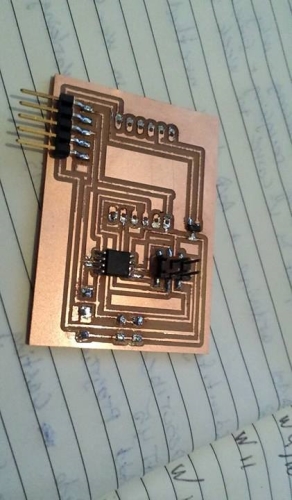
Designing the PCB.
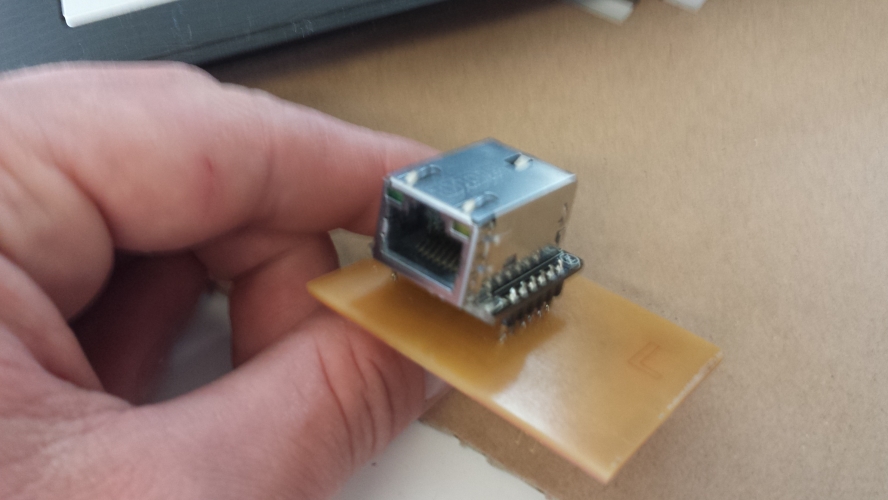
I wanted to try and use an ethernet module this week. The module that was found in stock was the WIZnet 820io ethernet module. The datasheet can be found here
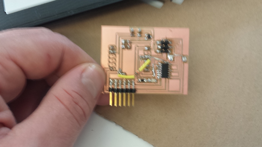
It took me some time to design it so that every pin was in correct posision, to put bluntly I had to mill out and redesign about 4 times. Every time I revisited the design board I thought to my self "man, that was a wierd mindfart, lets not do that again...". Anyways, I never got to the point of actually using it because I still have some things to improve, but I did learn some things.
Master/slave nodes.
After I gave up on using the ethernet module, I decided that it might be a good idea to go back and try out some of the things that were explained in the lecture. Eventually I used the node network to connect the motor shield as slave and the temperature sensor as master. The master sends 0's when the temperature and humitidy is below certain temperature and 1's if it goes above certain temperature, in which case the motorshield turns on a fan.
There were numerous problems that I encountered. I used the existing motor shield and the existing temperature sensor. They both had a 6 pin header, but I realized that they didint have the same free pins to use for communication, the MISO and MOSI line were free on one of the modules, but the MISO and clk line on the other. I first tried to solve that problem by making a customized 6 line cable, but swapping the MOSI and clk line. That turned out to be a bit of a headache. Then I made a dedicated PCB that swaped them for me.
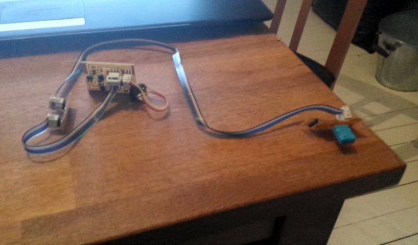
I programmed the temperature sensor to send me the information through the arduino serial monitor, and it worked fine, it sent me bunch of 0's when the temperature was fine, but 1's when it wasnt. Next I programmed the motorshield to do something when I sent it 1's, and it did. When I then connected them both togeather nothing seemed to work at first and it was a terrible headache because I had to unplug EVERYTHING, and it was quite alot of stuff, before I could trouble shoot - connect either to the pc through the FTDI cable to see what was going on, or to upload a new program.
arduino network code.