Computer Controlled Machining
To fulfill the assignment I decided to use both Solidworks and Fusion 360 to make the design. And for cutting I used EasyWorker MasterPro 2513 CNC machine.
Designing
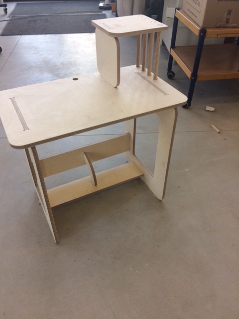
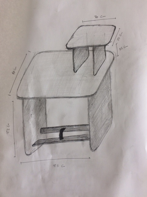
First step was to draw a rough hand sketch of the design. I wanted to make a study desk like this.
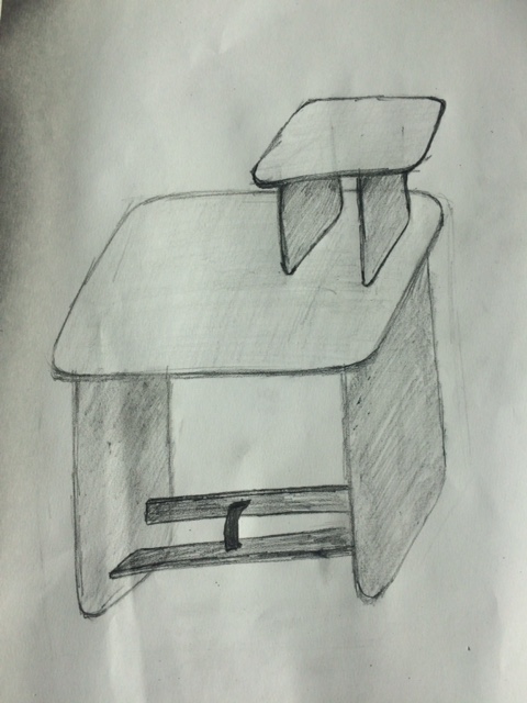
Then I added the dimensions after doing some research about the standards and also taking in consideration the size of the sheet of wood that I will be using.
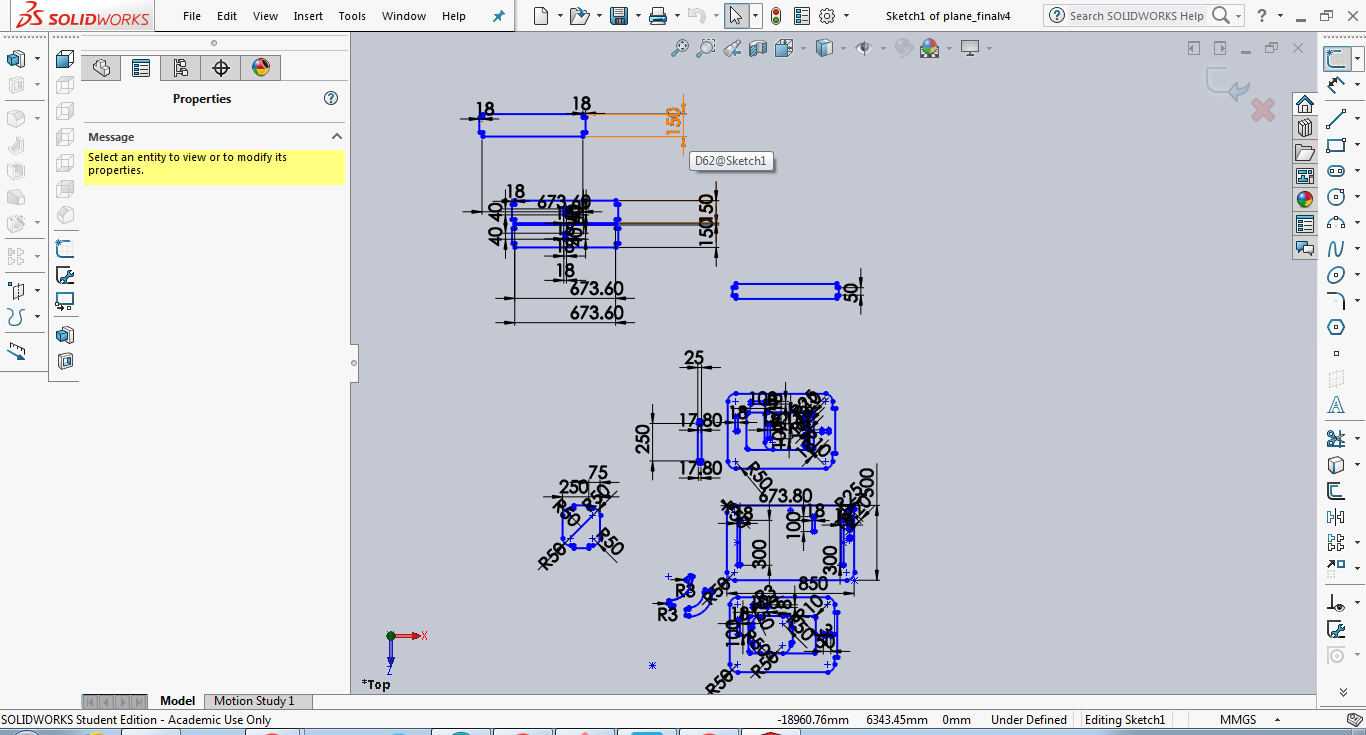
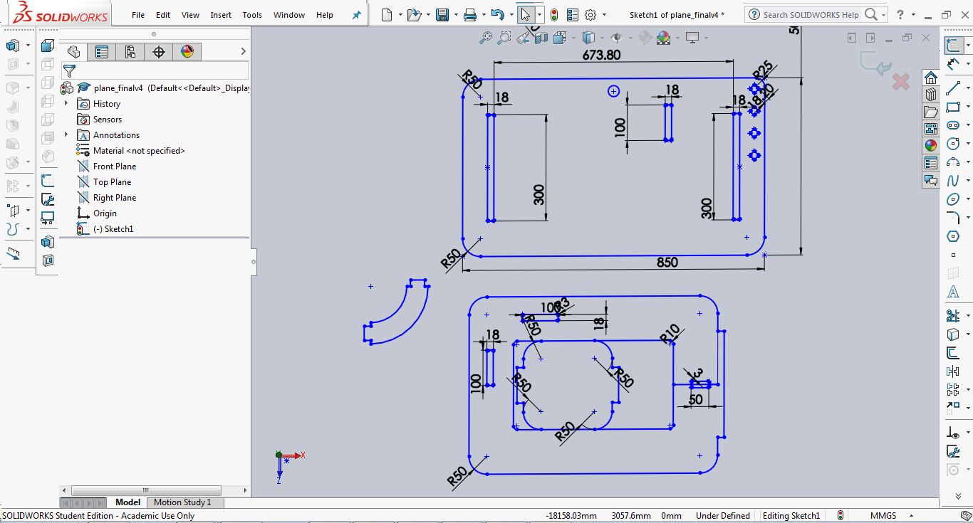
-I started by using Fusion 360 then I replicated the design again in Solidworks to have a comparison between the 2 of them.
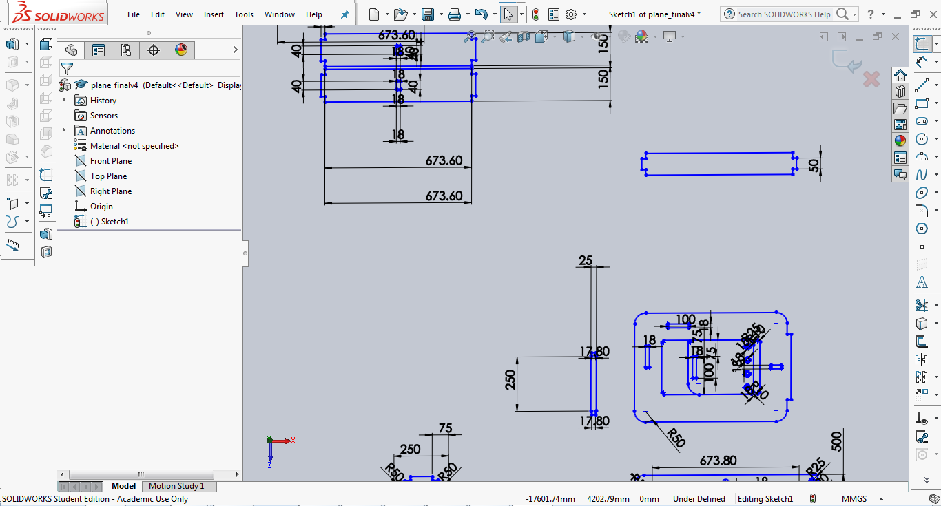
In this section I will be listing all the commands I used to draw the 2D sketch.
Fusion 360:
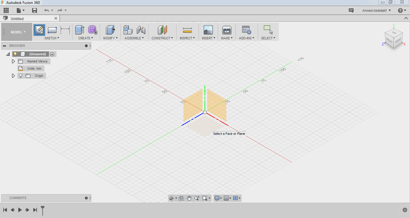
-First I created a new sketch as shown before in previous documentation and I also used mostly the same commands as before.
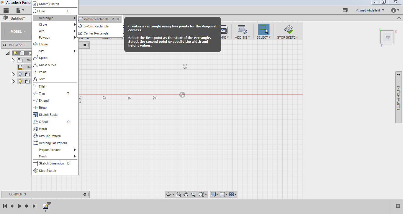
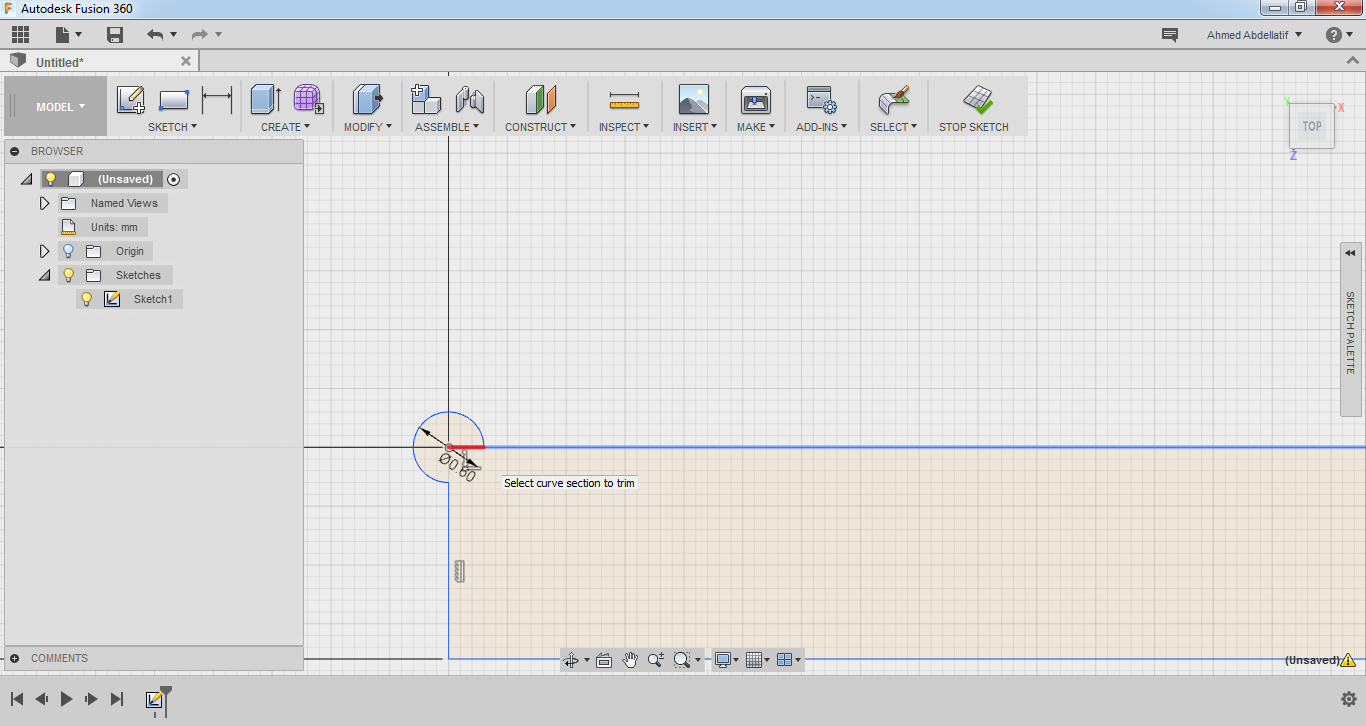
-I started by drawing all the rectangles as outlines of all the pieces of the desk using the rectangle tool.
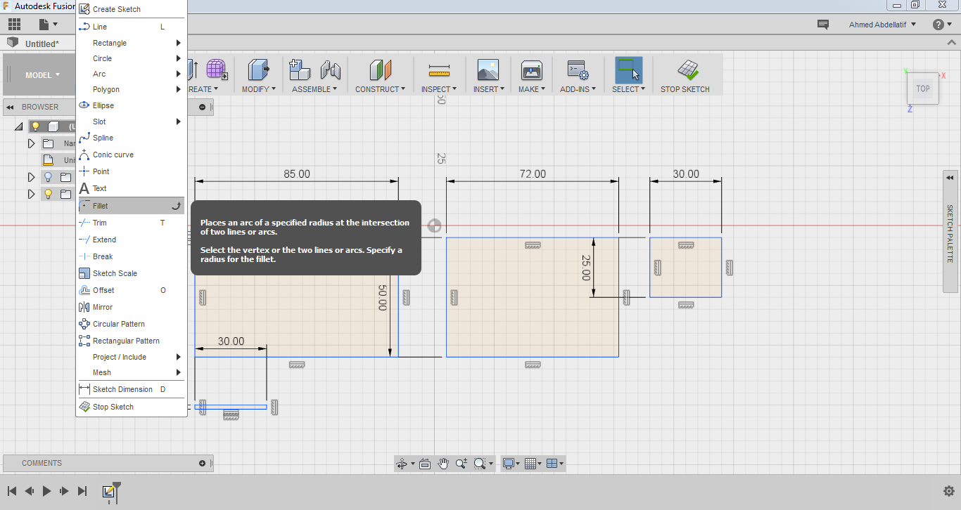
-I added some fillets using the fillet tool
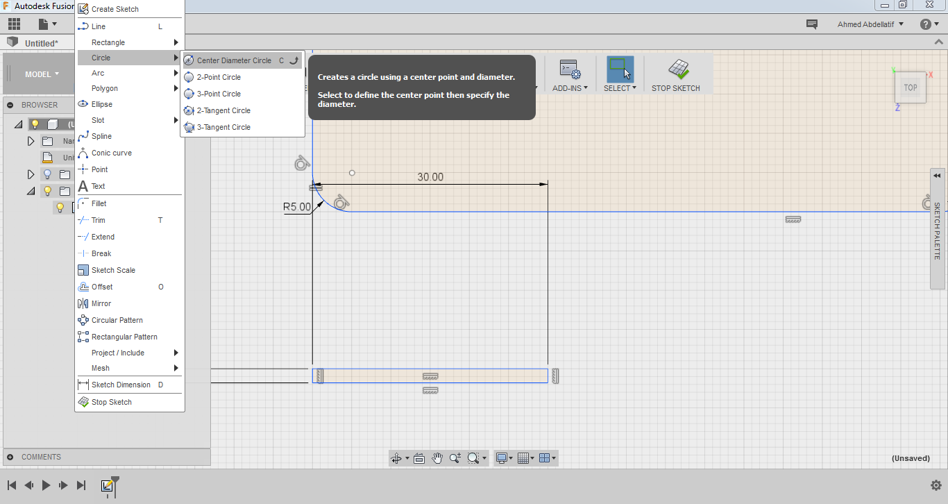
-I added some circles where I needed them using the circle tool. The reason why I needed circles on corners of inside 90 degrees is because the milling tool is 4 mm in diameter so it needs some allowence to work within.
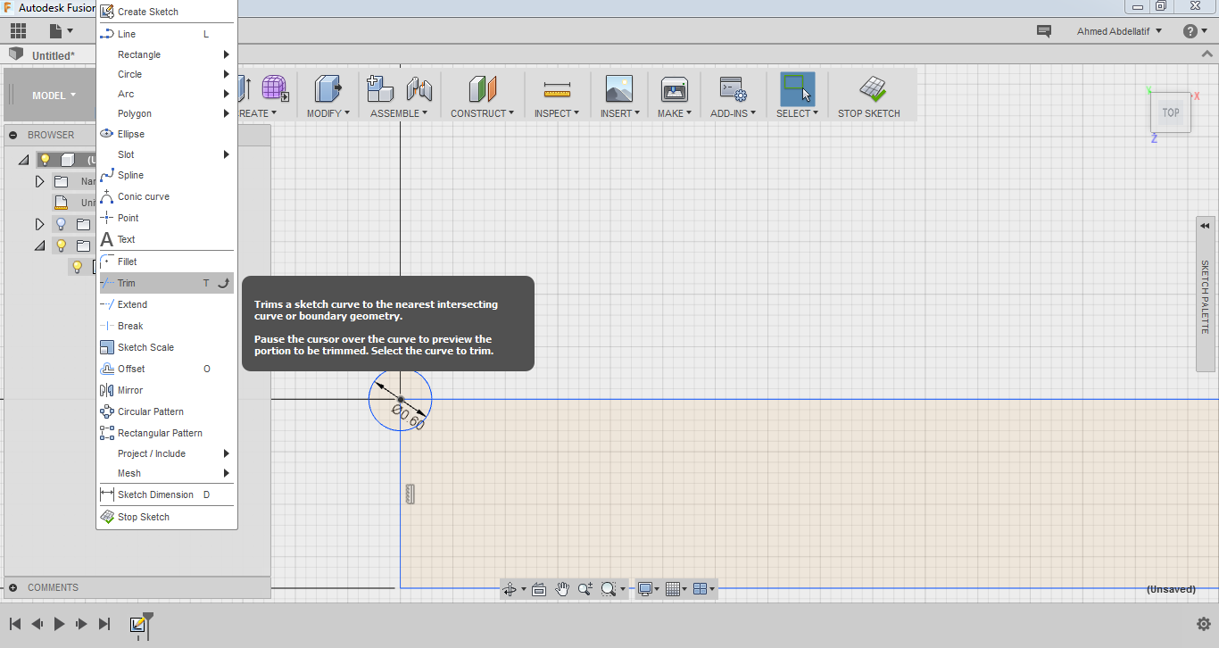
-I used trim tool to trim the parts I don't need.
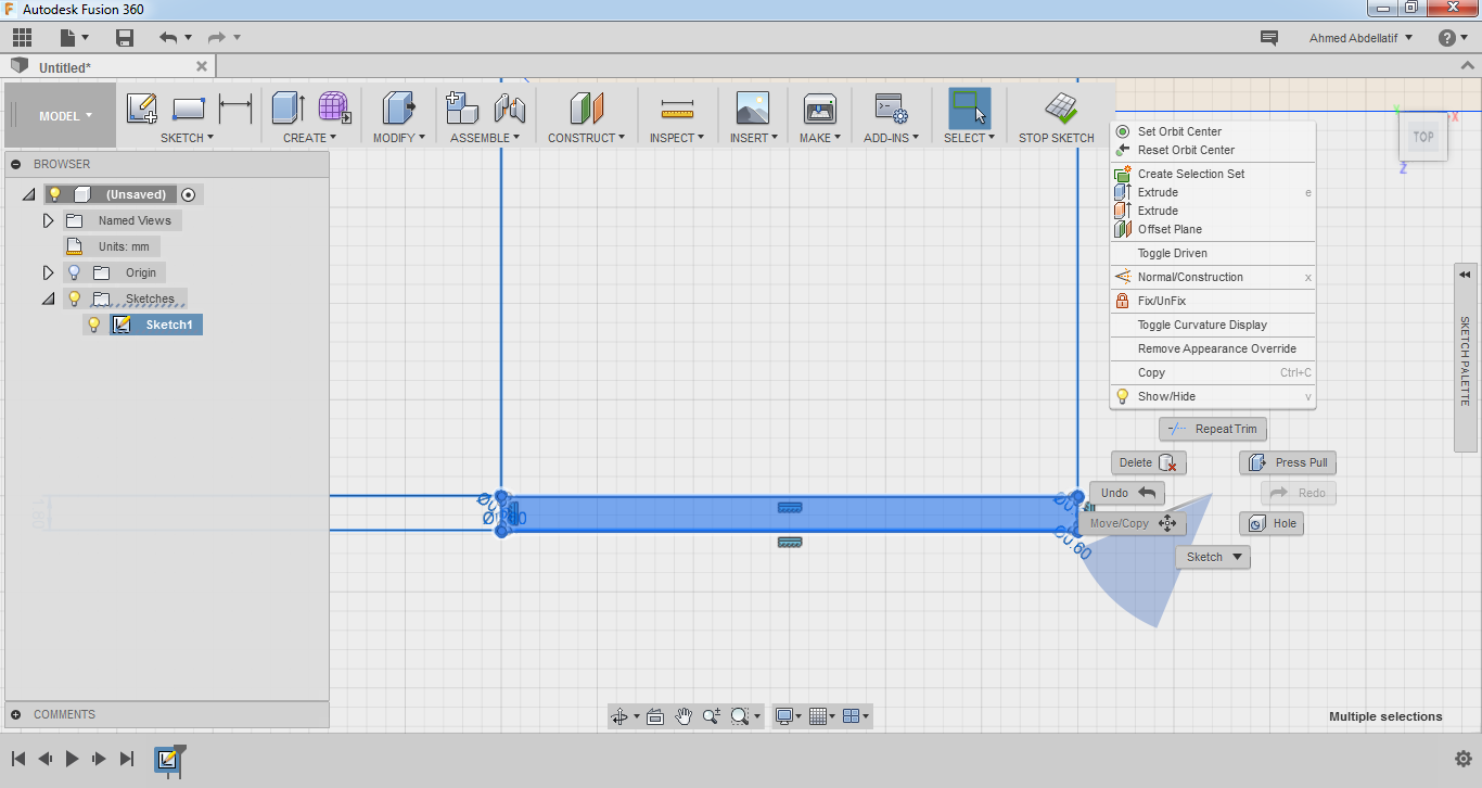
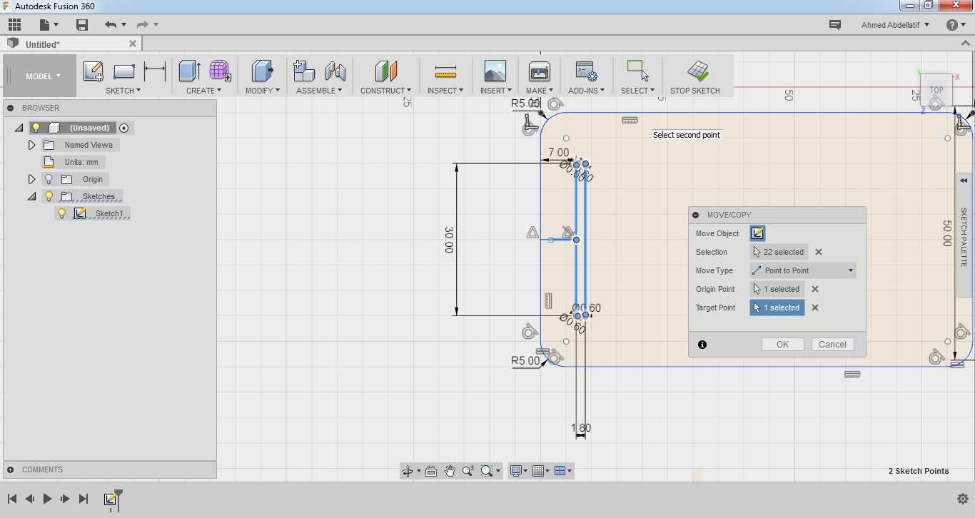
-To rotate something I selected It, right clicked it and chose Move/Copy. I used free mover and the rotating snaps to rotate it.
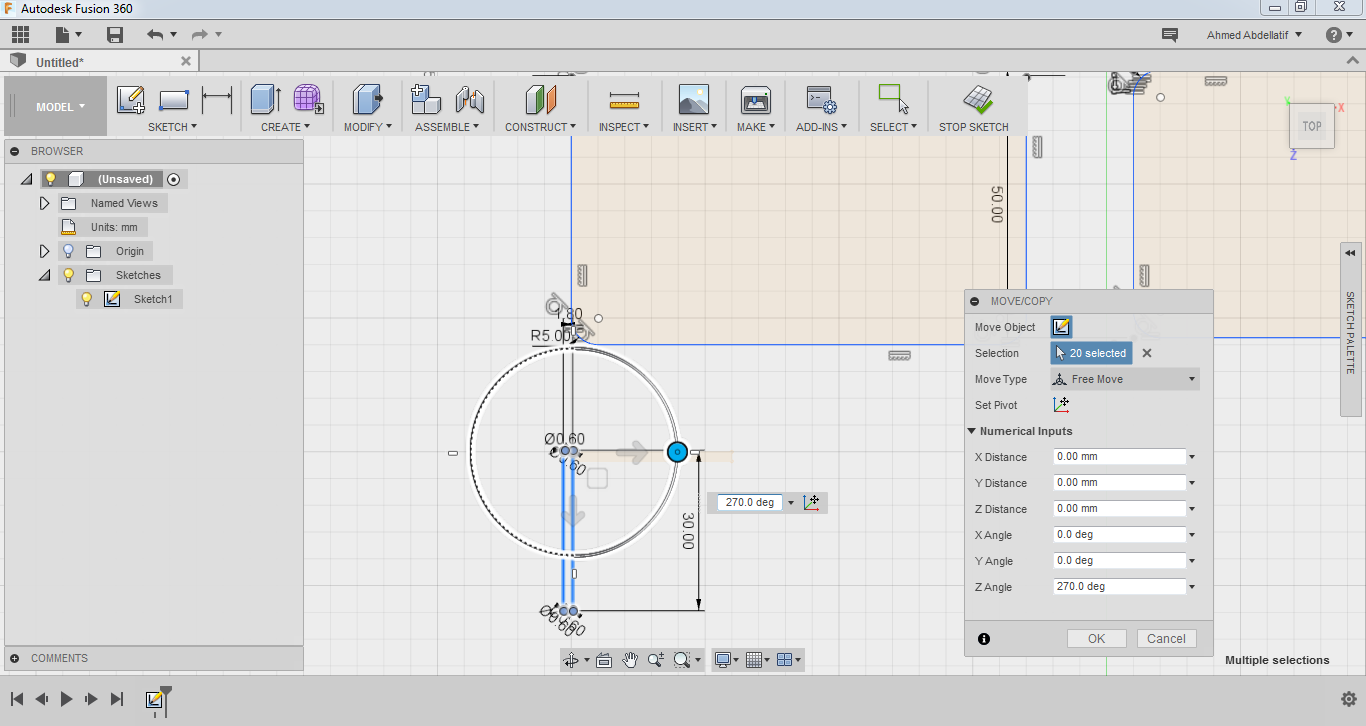
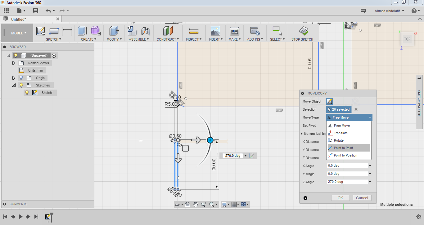
-To move something to a point I selected It, right clicked it and chose Move/Copy. I used point to point.
-I used exactly the same commands to reach my final design
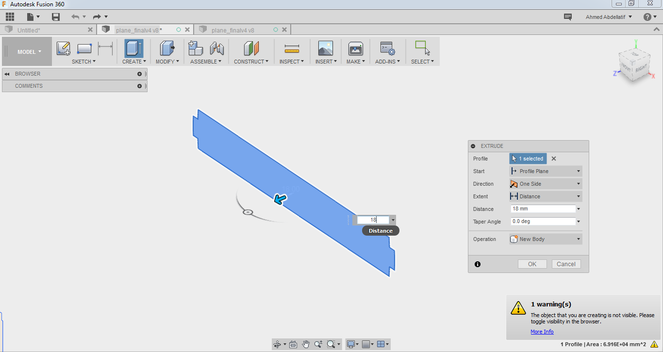
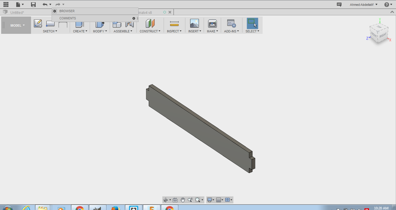
-I extruded all the pieces by clicking on them and pressing E and then entering the thickness of the material and pressing Ok.
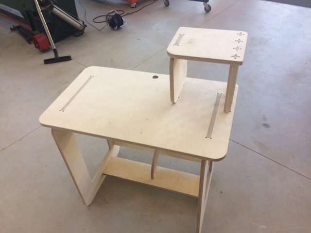
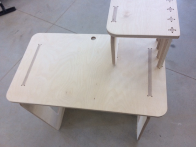
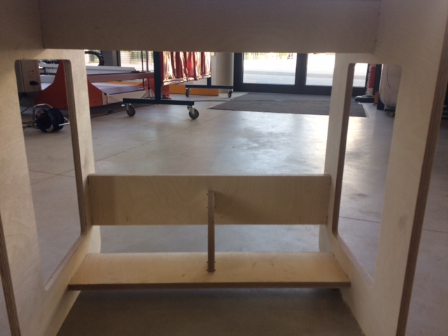
-After extruding everything I assembled them together using move to point as mentioned above.
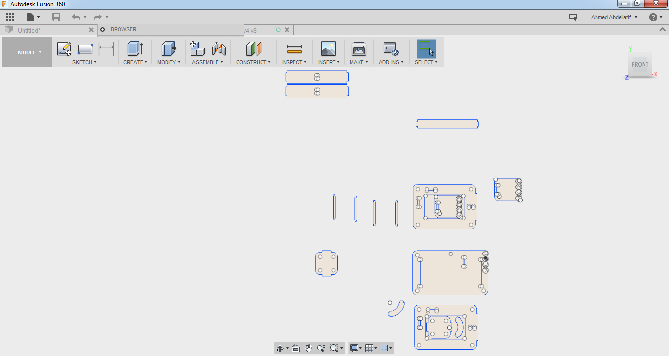
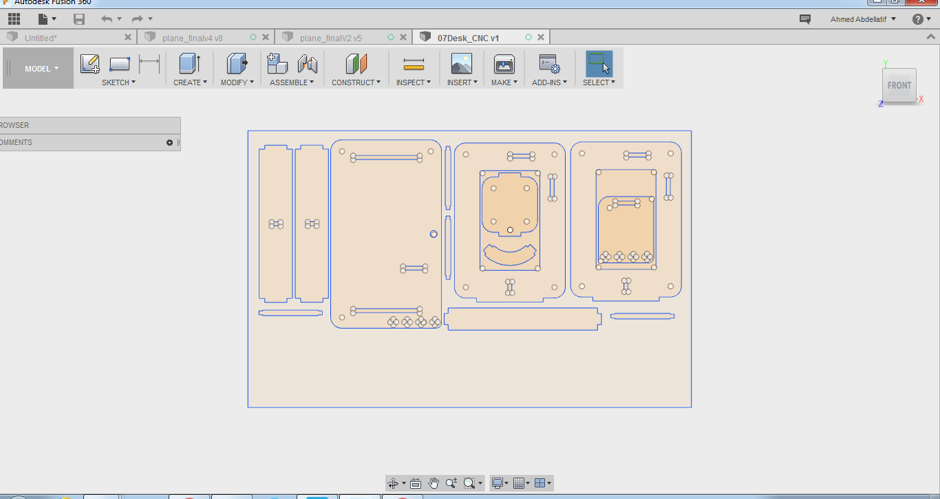
-Finally I nested everything together to make the best out of the material and to save the machining time as much as possible.
Solidworks:
-First I created a new part as shown before in previous documentation and then started drawing the 2D sketch using also the same commands as before and the same work flow of fusion.
-This is how it looked.
Conclusion:
Personally I think SolidWorks is better in keeping track of the work flow and the time line of commands also It's better when it comes to real time changes made to sketch and their effect on the extruded parts. On the Other hand I think fusion is easier in assembly and more user friendly regarding this part in particular.
Milling
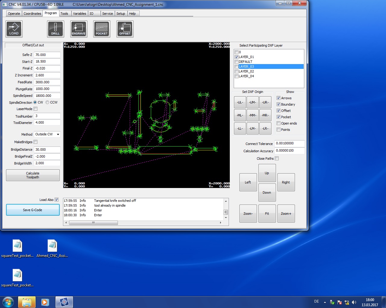
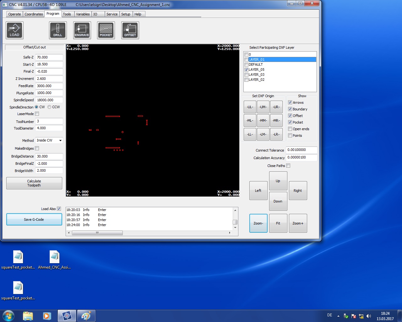
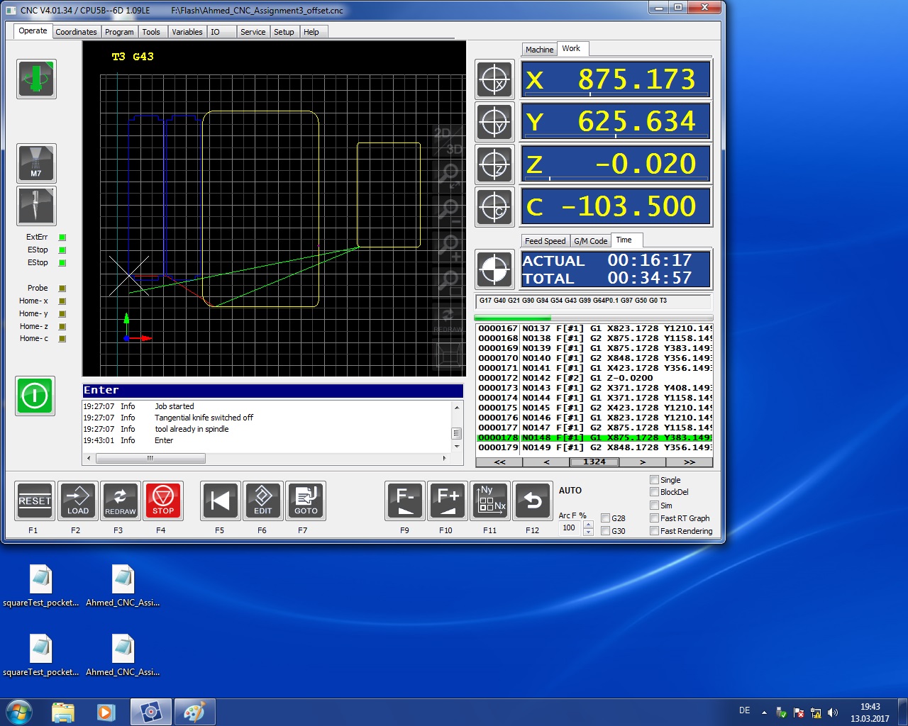
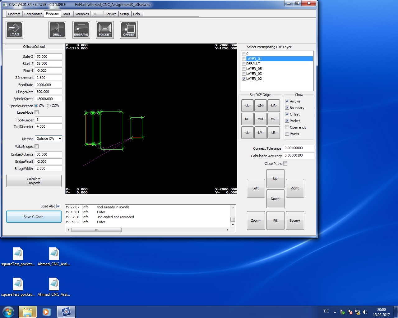
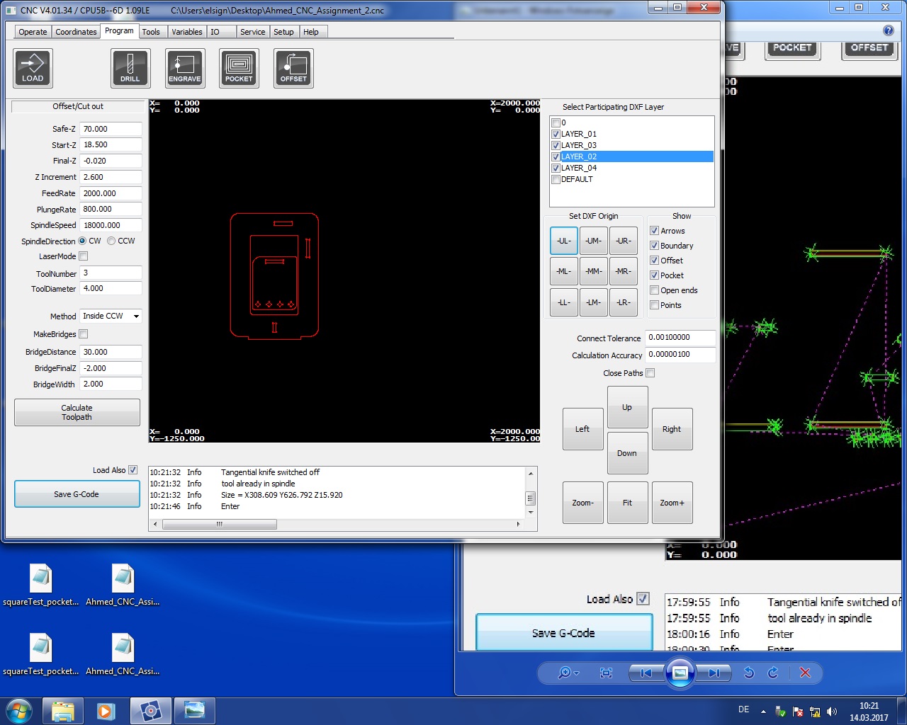
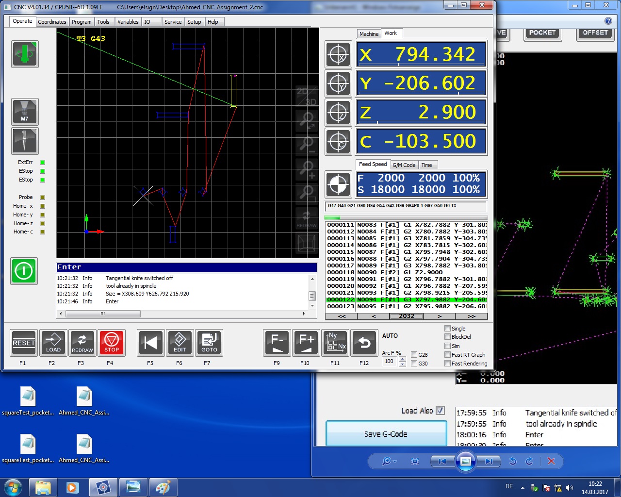
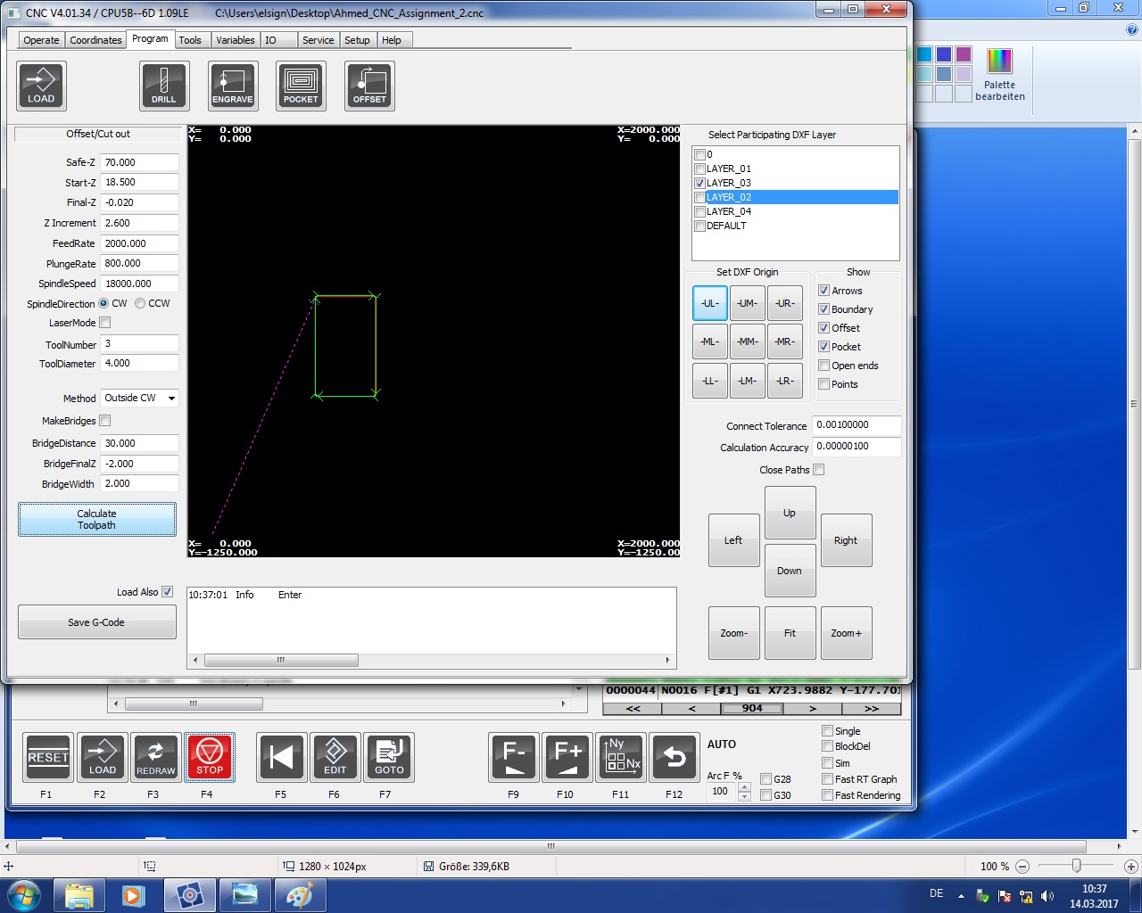
-After Having the nested version of the design ready I put the parts in layers so I can have different jobs for them. I made four layers for four jobs. Finally I loaded it into the machine's software and chose the following settings:
Safe-Z-->70.00
Start-Z-->18.5
Final-Z-->-0.02
Z INcrement-->2.6
FeedRate-->2000
PlungeRate-->800
SpindleSpeed-->18000
Spindle direction-->CW
Method-->I chose Inside CW for the slits of the joints only and for the other jobs I chose Outside CW.

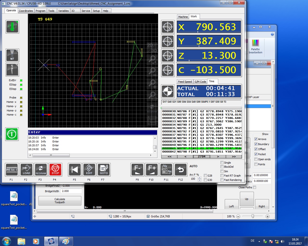


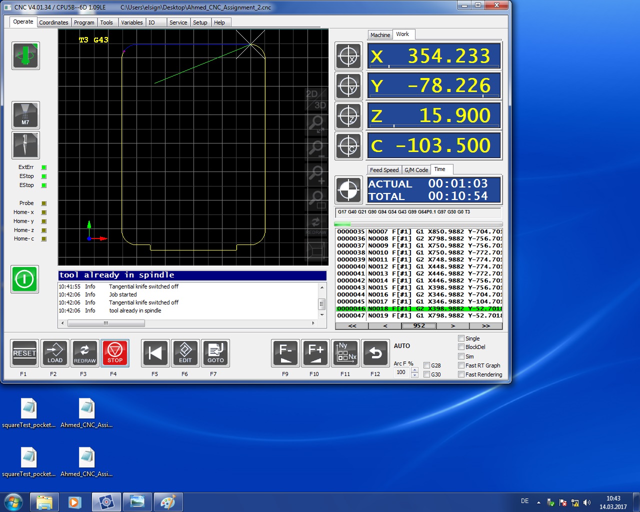

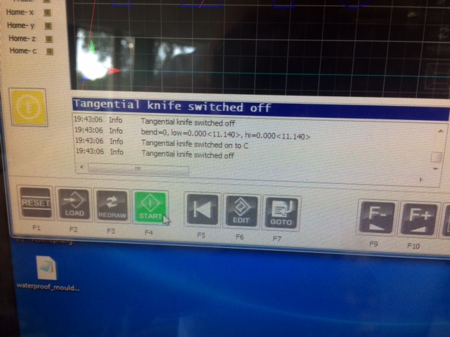
Here are the steps to use the machine:
Home the machine
.JPG)
Put the material on the machine
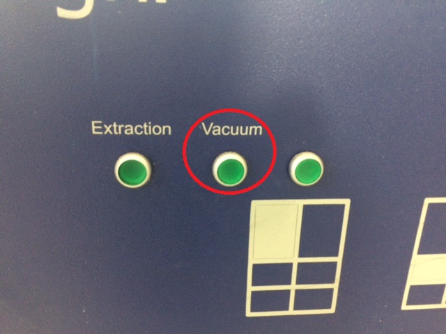
Start the vaccum of the bed
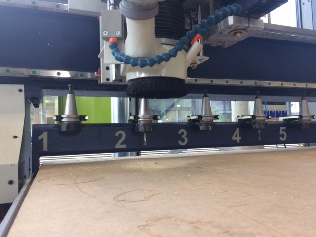
Pick the tool
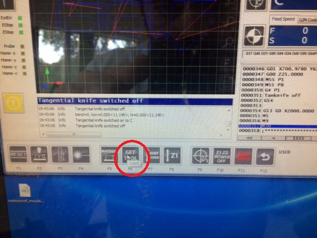
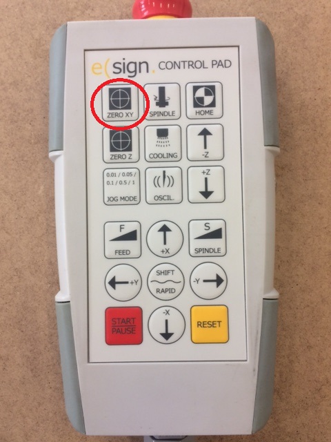
Set the zero point for X and Y
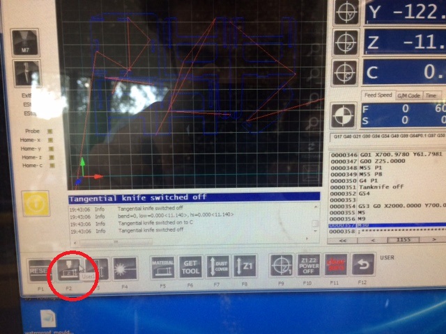
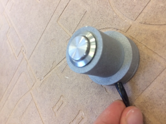
Set the Z height
Turn on the filter
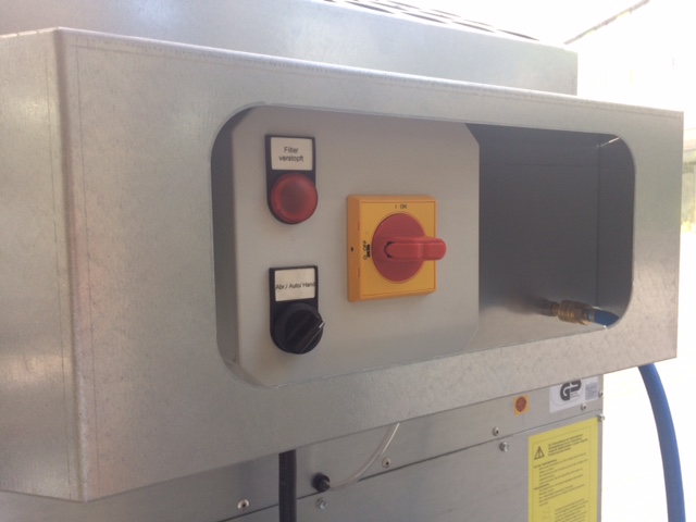
Put the dust cover down
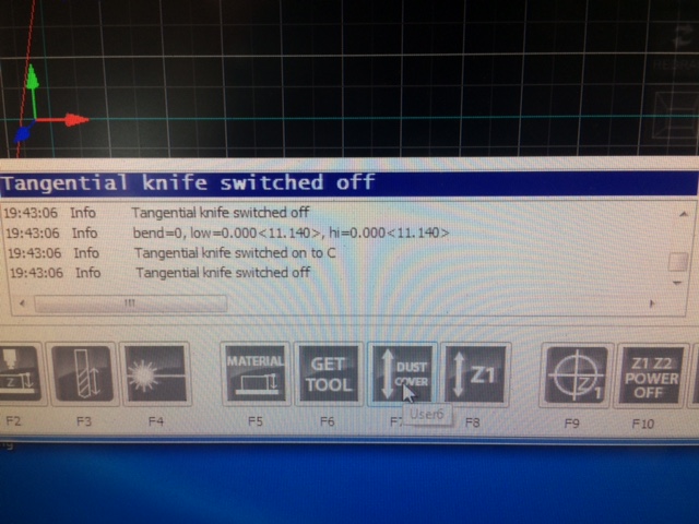
Start the job
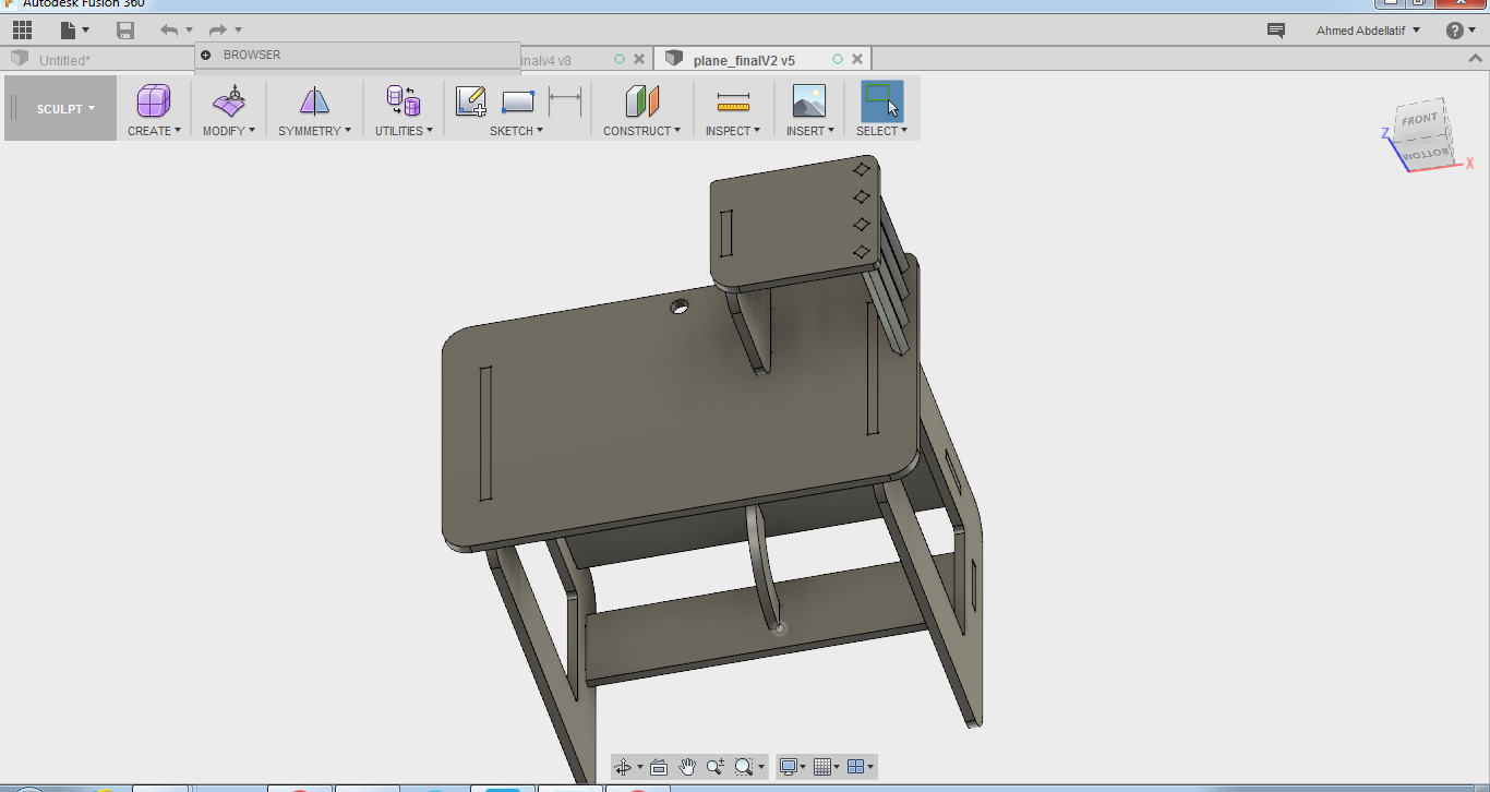
Final product