
3D Printing and scanning
Also we need to scan a 3D object using a 3D scanner.
3D printing is an additive fabrication technique. The idea behind it is to heat a material like PLA and extrude it through a nozzle while moving along the 3 axes according to the G-code of the job adding layers of material one on top of the other until the object is formed.
3D Designing and Printing
Designing:
My Idea is to design a chain that forms a closed loop. The reason why this can not be done suptratively is because of the undercuts and hidden spots that the milling machine wont be able to mill.
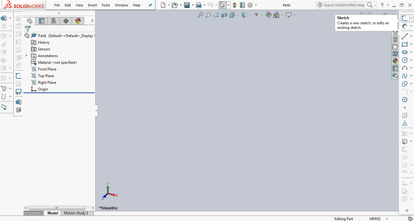
-I started by choosing to design a part and then created a new sketch.
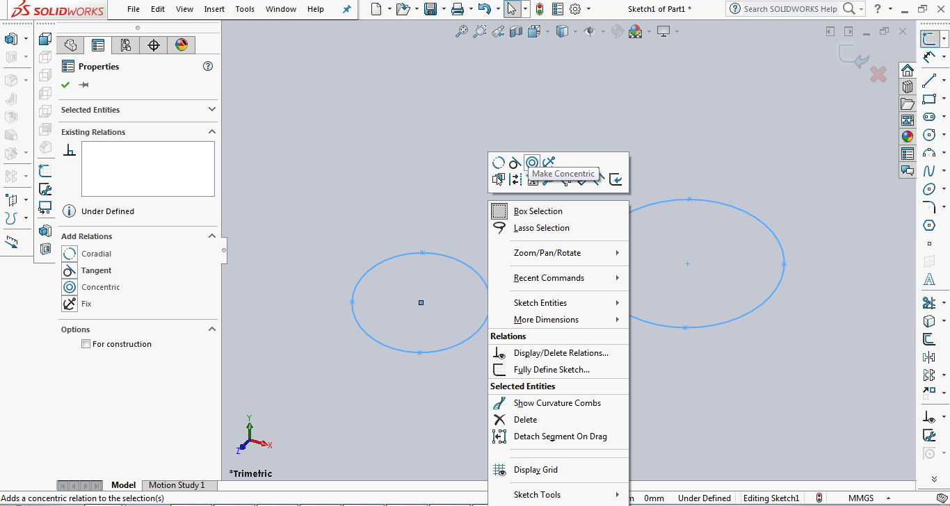
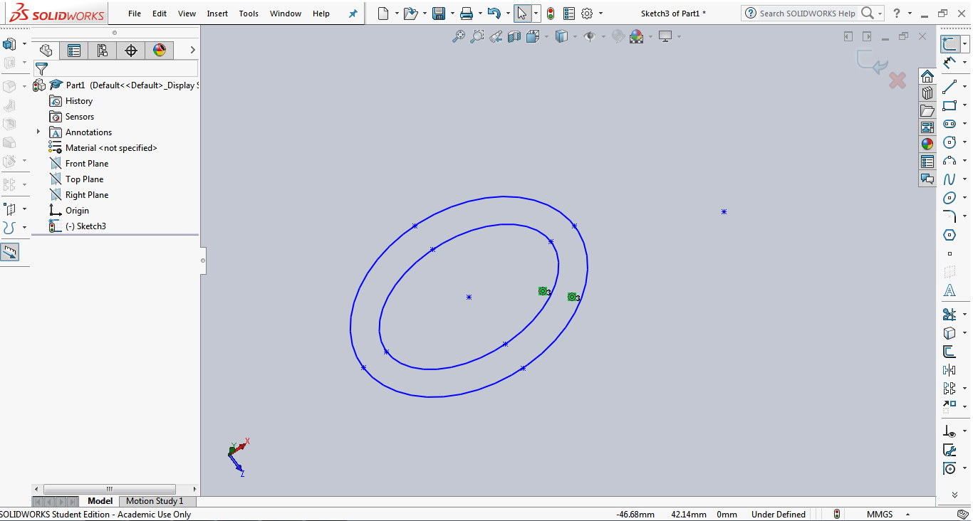
-I started by drawing 2 elipses using the elipse tool and setting the 2 radii of each elipse.
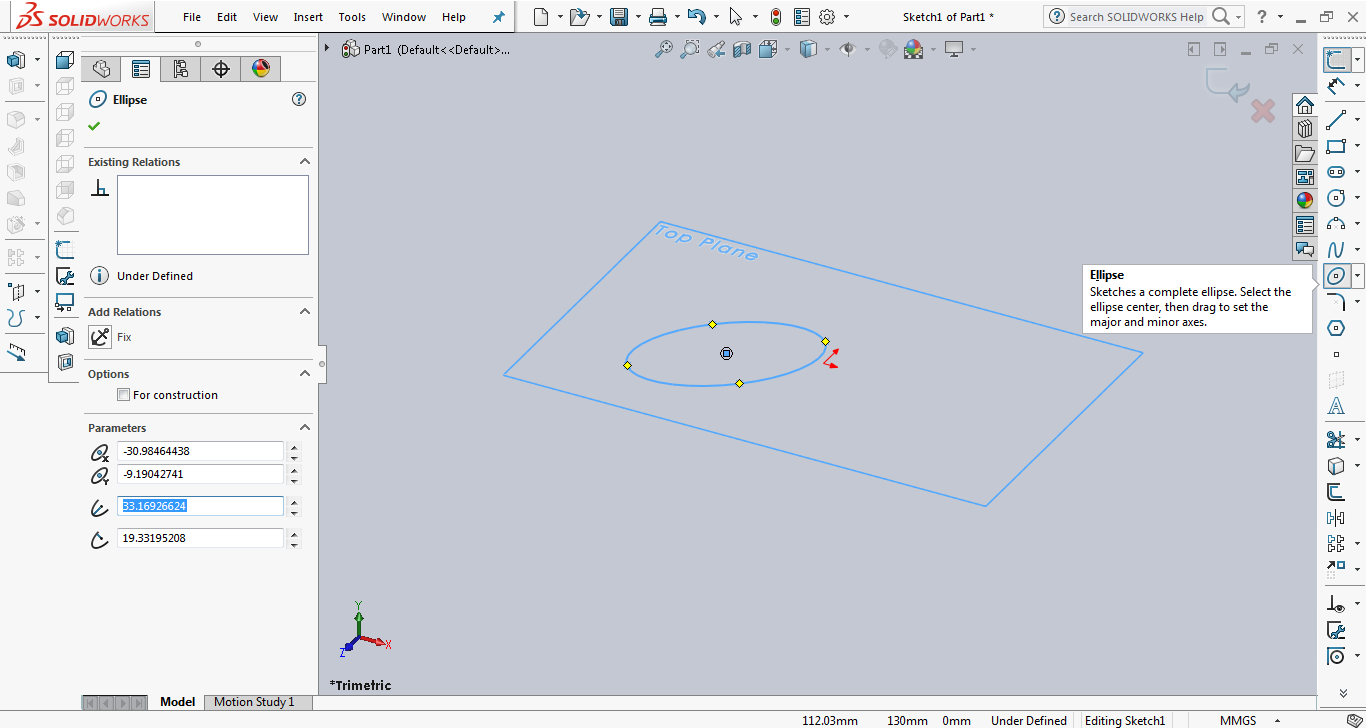
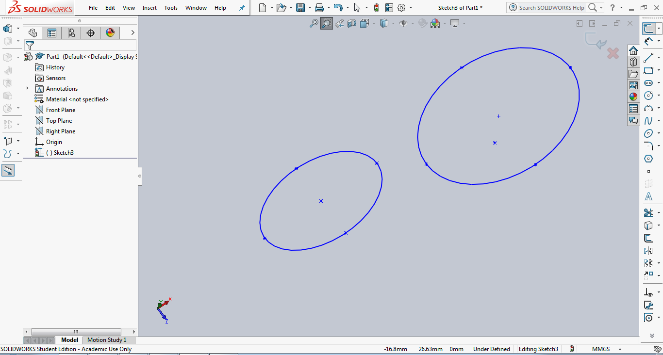
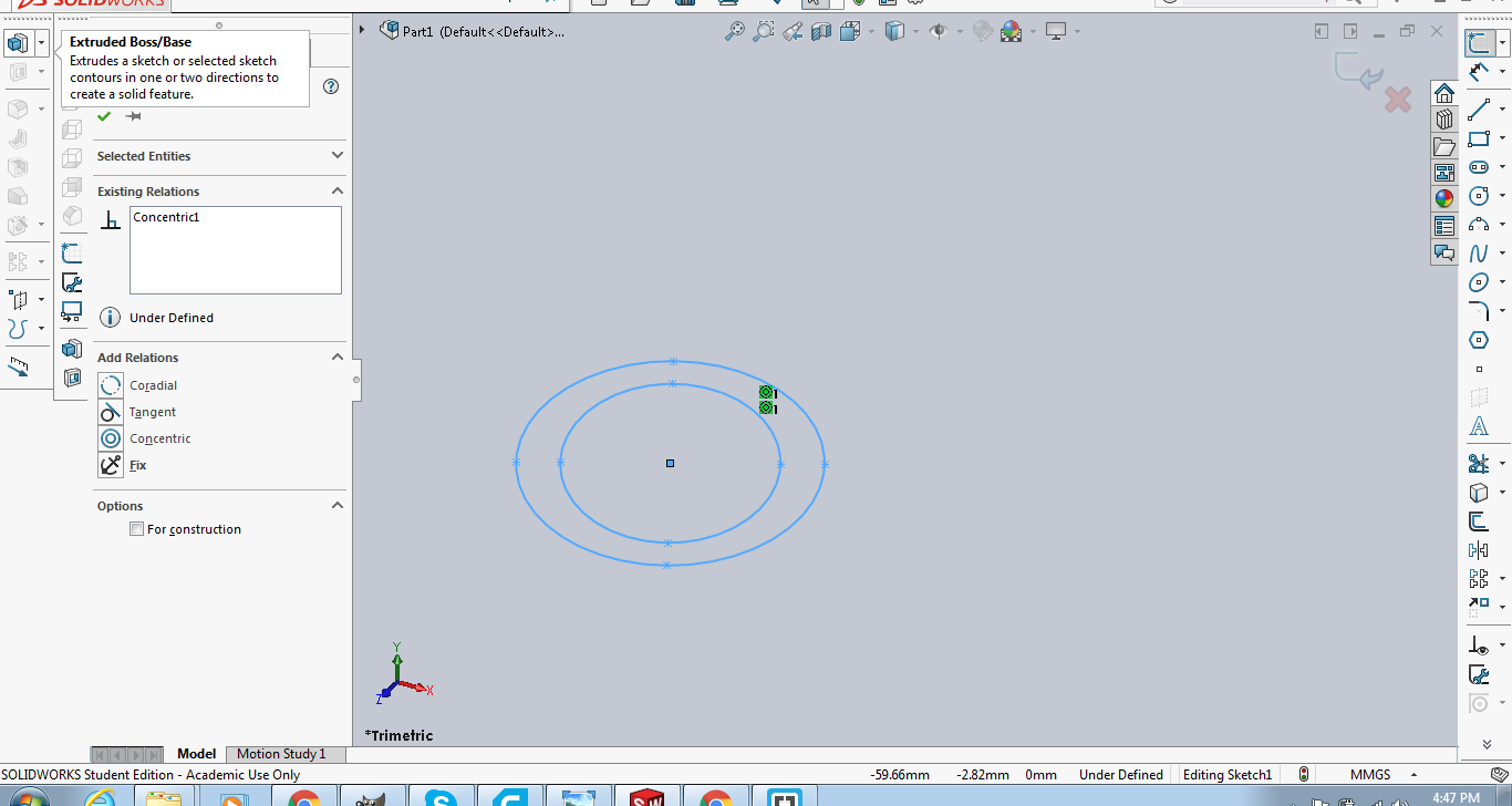
-I constrained the 2 elipses to be concentric by selecting them and then right clicking and choosing concentric constraint.
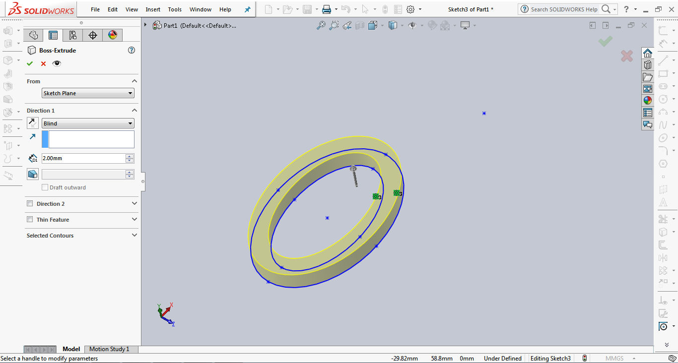
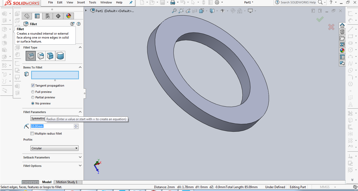
-Next thing I did was to extrude this drawing into an object.
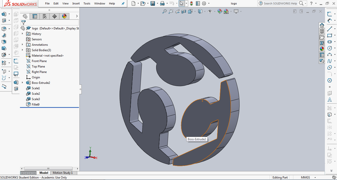
-I filleted the edges of my object using the fillet tool.
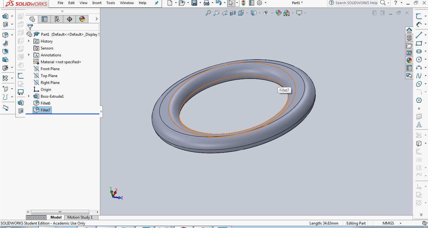
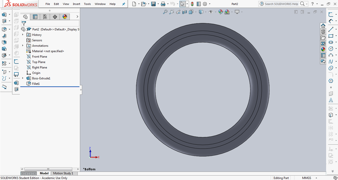
-This is the first part of my model at this point it was done. The second part is almost exactly the same except that the 2 radii of the elipse are the same in other words the base of the sketch is a circle this time not an elipse.
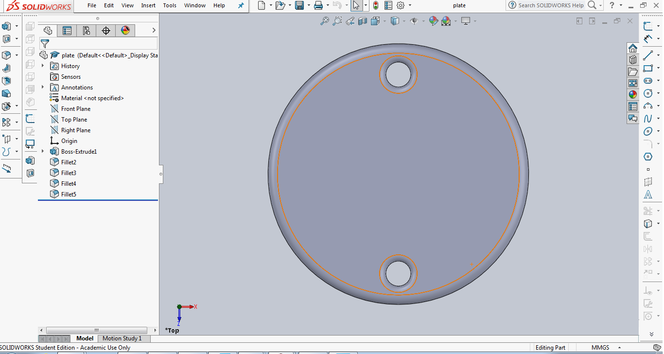
-I went on with creating the third part. I used pretty much the same sequence. Firstly I created a new part and started a sketch. Then I used circle command, then extrude and finally fillet.
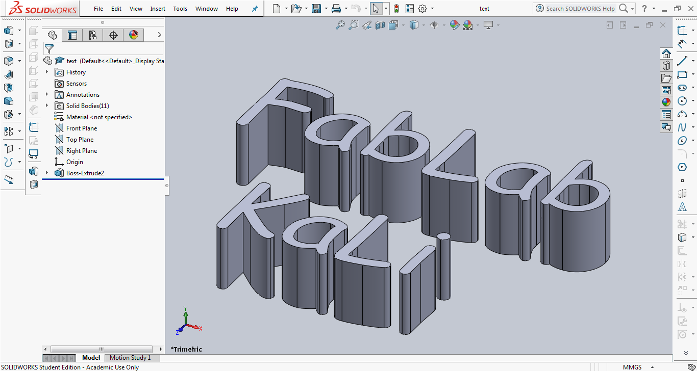
-For the fourth part I wanted to add an extruded text. I used the text tool to add the text .
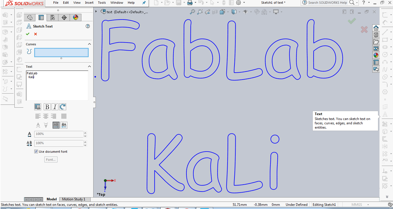
-I extruded the text using the extrude tool. This was the final step now I have the fourth part ready.
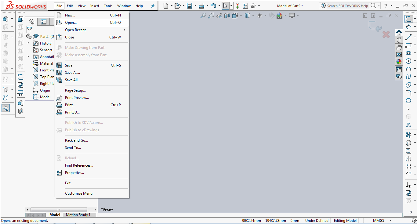
-For the final part I used the FabLab logo DXF file I already made before as part of Week three assignment. I created a new part and imported the file.
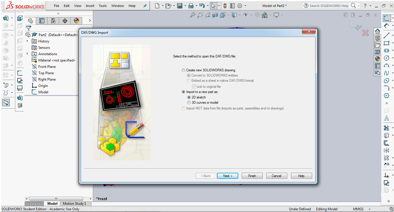
-I extruded the drawing into an object using extrude command.
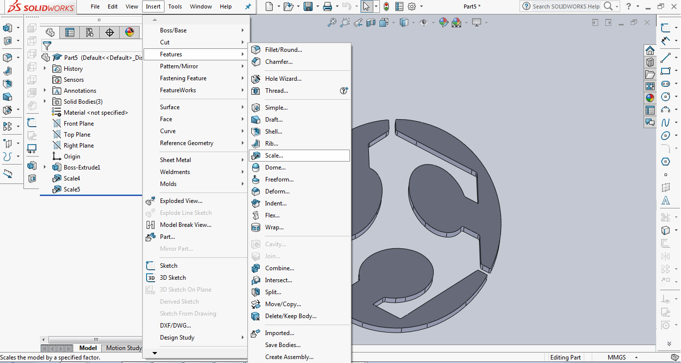
-Next thing I did was to scale it down by going to Insert >Features >Scale ,then I entered the appropriate scaling factor and pressed Ok.
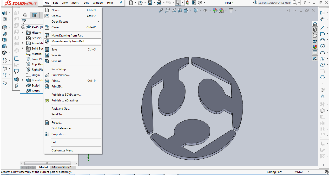
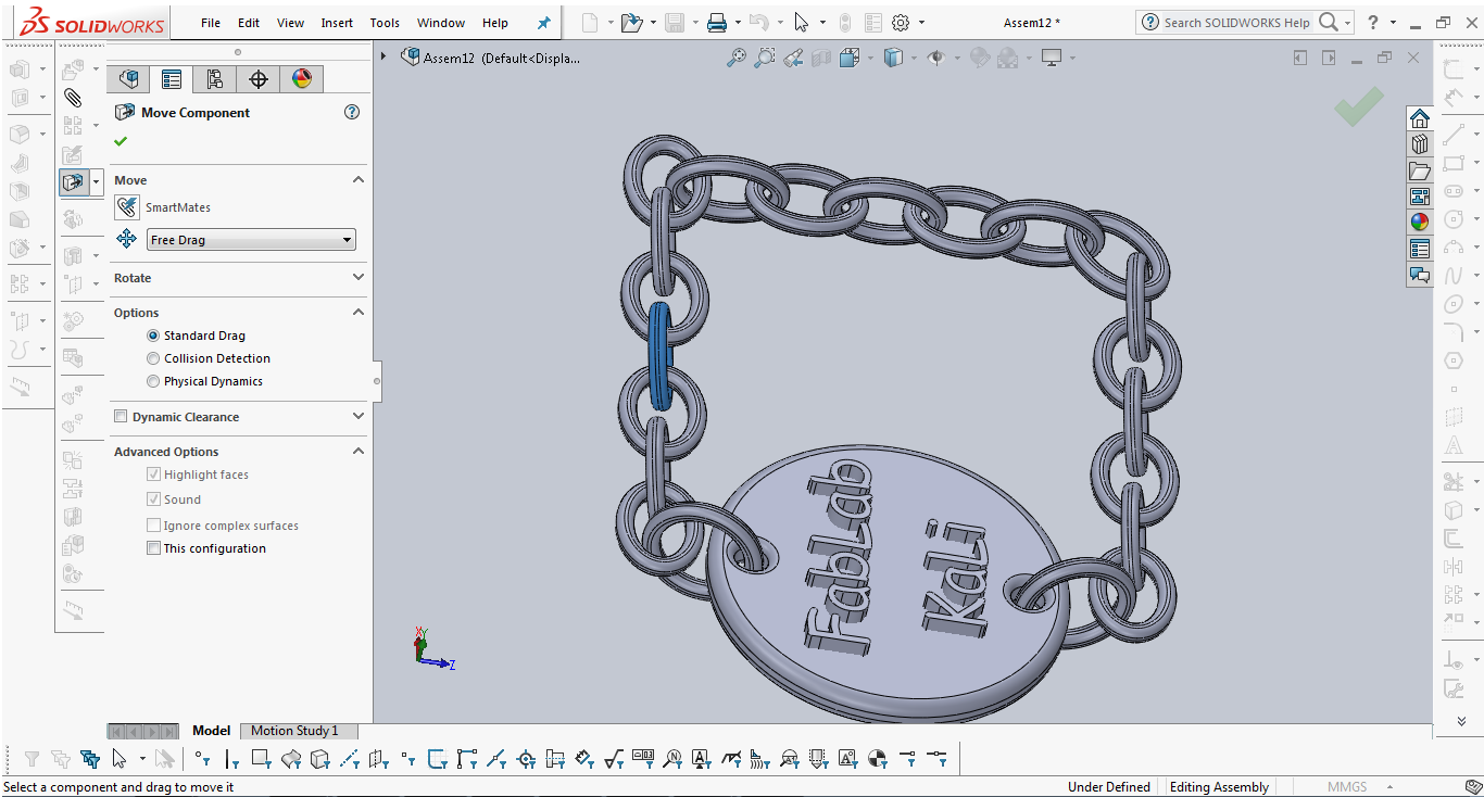
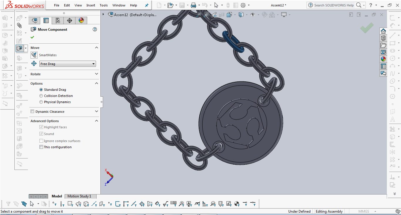
-At this point all the parts were ready to be assembled. I created a new assembly by clicking on Make Assembly from Part from file drop menu.
-I inserted all the other components to the assembly by clicking on browse and choosing the components.
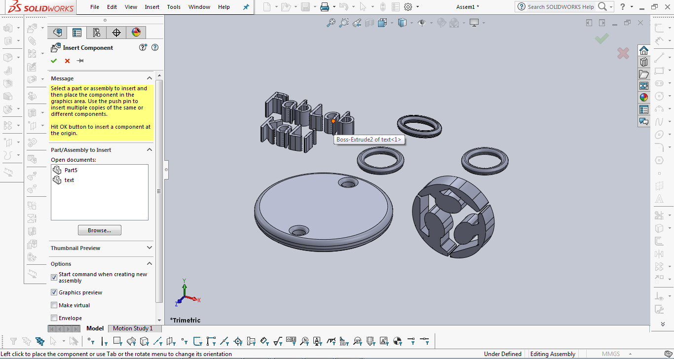
-After inserting all the components I started assembling them by placing them correctly.
Here are the commands I used:
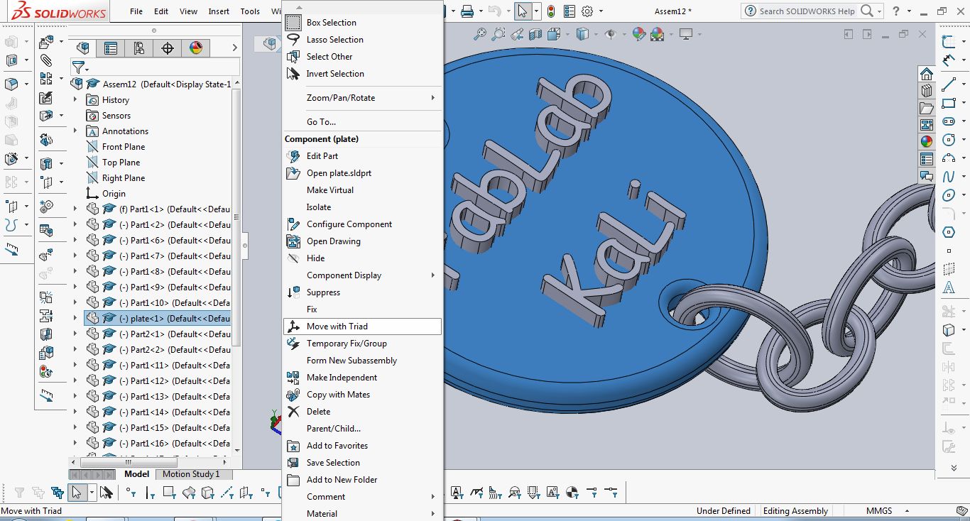
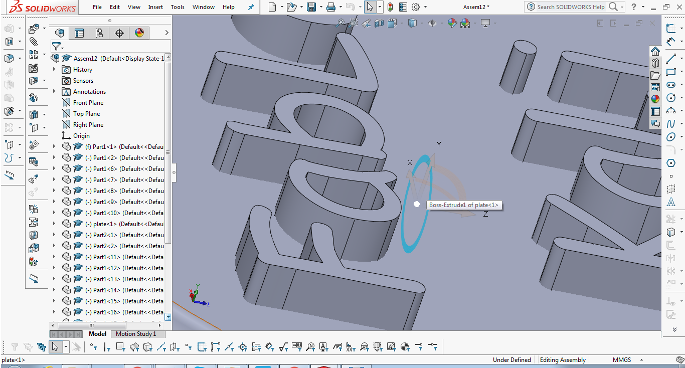
First: I selected the first component, right clicked and chose Move with triad
Second: I Copied part one and part two couple of times as I will need them, I did this by selecting them and pressing CTRL+C then CTRL+V.
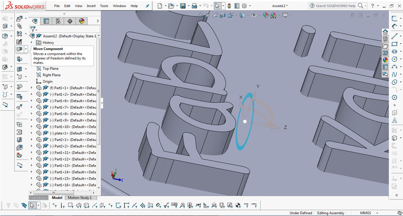
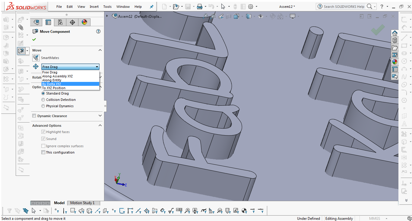
Third: I used the move commmand. I chose to move by Detla XYZ.
I kept using those commands until I reached what I wanted
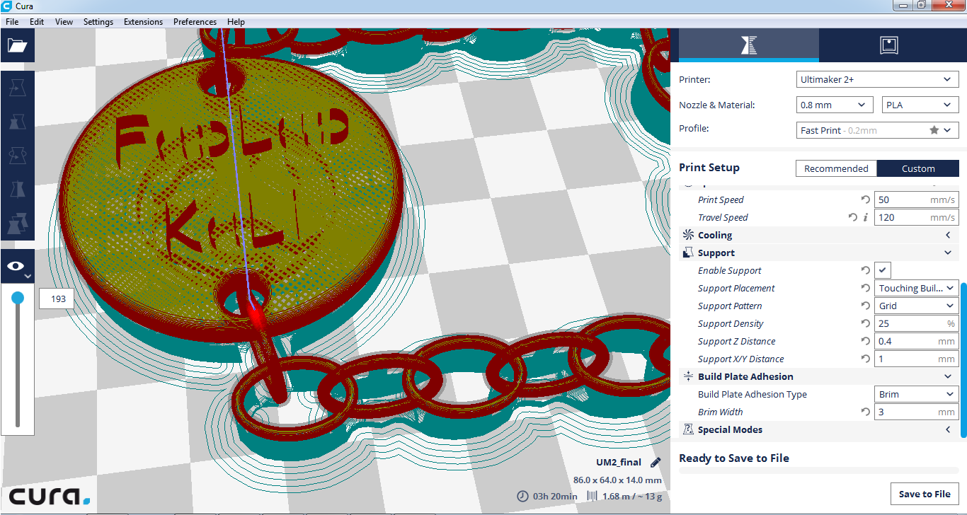
Slicing:
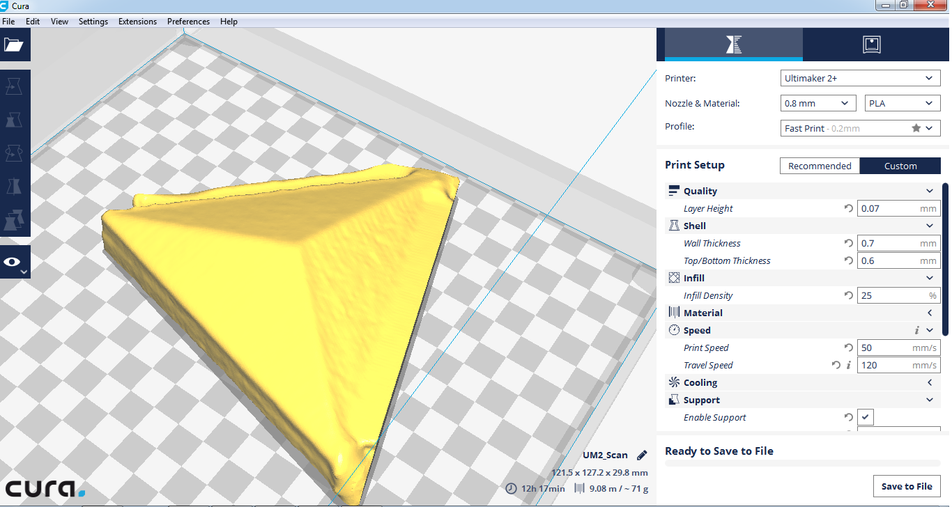
I used Cura to slice my model for Ultimake 2+ printer with nozzle diameter of 0.8mm.
-Here are the settings that I used:
Layer height: 0.07mm --> The thinner the layer height the better the quality, I wanted good quality
Wall Thickness: 0.7 mm--> Because some parts of the chain were really small I chose to go with a thickness less than 1mm
Top/Bottom Thickness: 0.6mm--> Same as with wall thickness
Infill denisty: 25%--> Because it's a small piece and it's not going to sustain any forces or stresses
Print speed: 50mm/s--> It's a moderate speed to get good printing quality
Travel Speed: 120mm/s--> Also affects the quality of the print if the head moves too fast after printing it may cause some damage
Enable support: Yes--> As some parts are not touching the builplate of the machine
Support placement: Touching Build Plate
Support Pattern: Grid
Support Denisty: 25%--> I tried with less but I saw that not all the parts are properly supported
Support Z Distance: 0.4 mm--> Distance between support and actual object in Z direction, The less the distance the better the quality of the surface but also the harder to remove support later on.
Support X/Y Distance: 1mm--> Horizontal distance between the object and support, I wanted to be able to remove support easily without breaking the small pieces
Build plate Adhesion Type: Brim--> Makes a brim around the object to fix it to the buildplate
Brim Width: 3--> Because the object is really small so no need for more than this

Printing:
I used Ultimake 2+ printer with nozzle diameter of 0.8mm along with PLA of diameter 2.85 mm.
-Here is how it looked after printing and before removing supports
.JPG)
.JPG)
-Here is how it looked after removing supports
.JPG)
.JPG)
.JPG)
Problems and Commments:
-During my first printing trial I was using 8% infill for support I thought that it would be okay but I noticed that it was not good enough to hold the details of the model so I increased it to 25%.
-One other problem was that not all of the text part was not printed succesfully some pieces are missing.
-Also the surface of the model facing the supports came out a bit rough I would say that this is because of the Z Distance but I believe it would have been very hard to remove the supports if I decreased the distance because of the small size of the object.
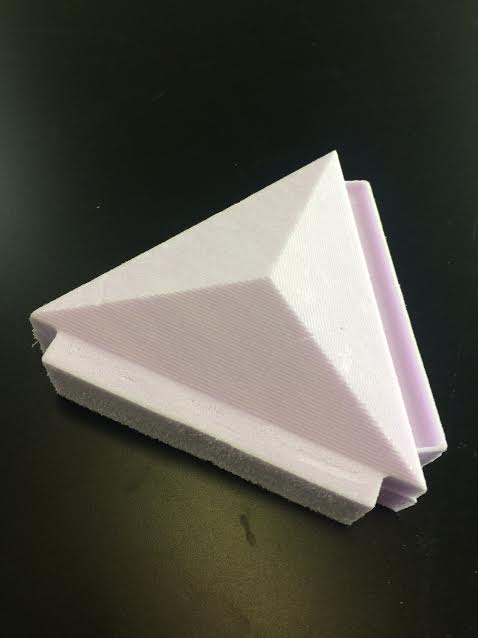
3D Scanning
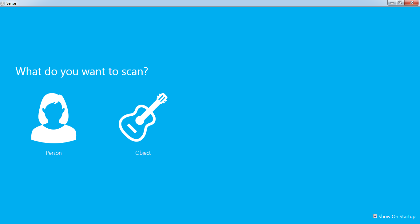
-I used Sense 3D scanner along with its Software .
This is the object I scanned
-First step is to choose the object to be scanned. I chose object.
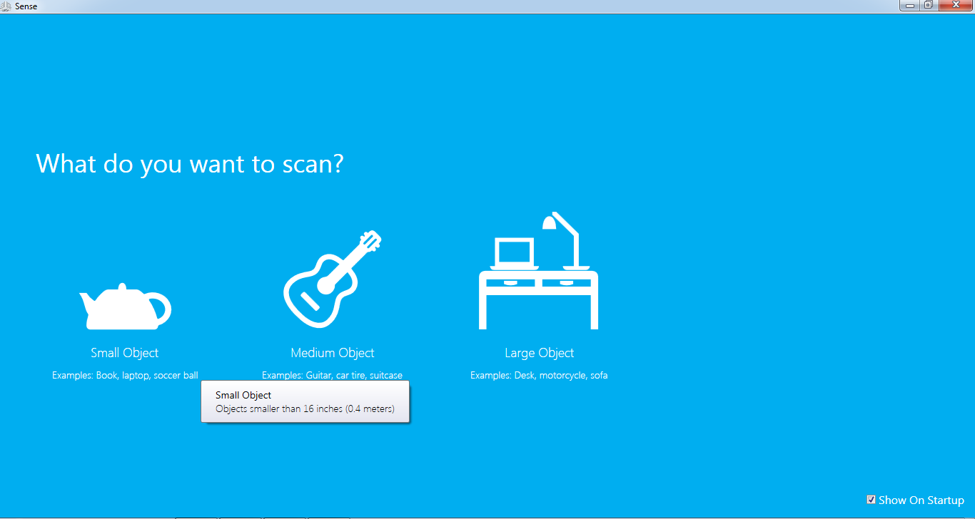
-Then I chose small size object.
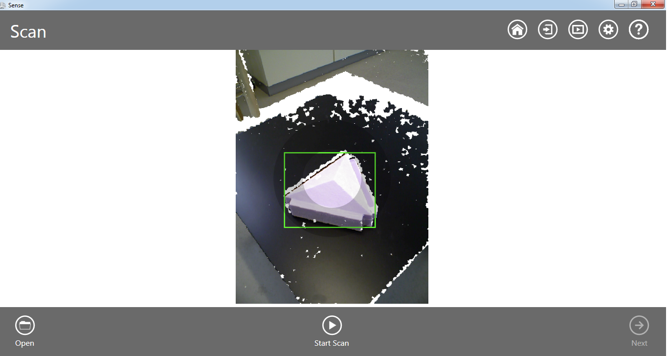
-I started the scan while focusing on the object.
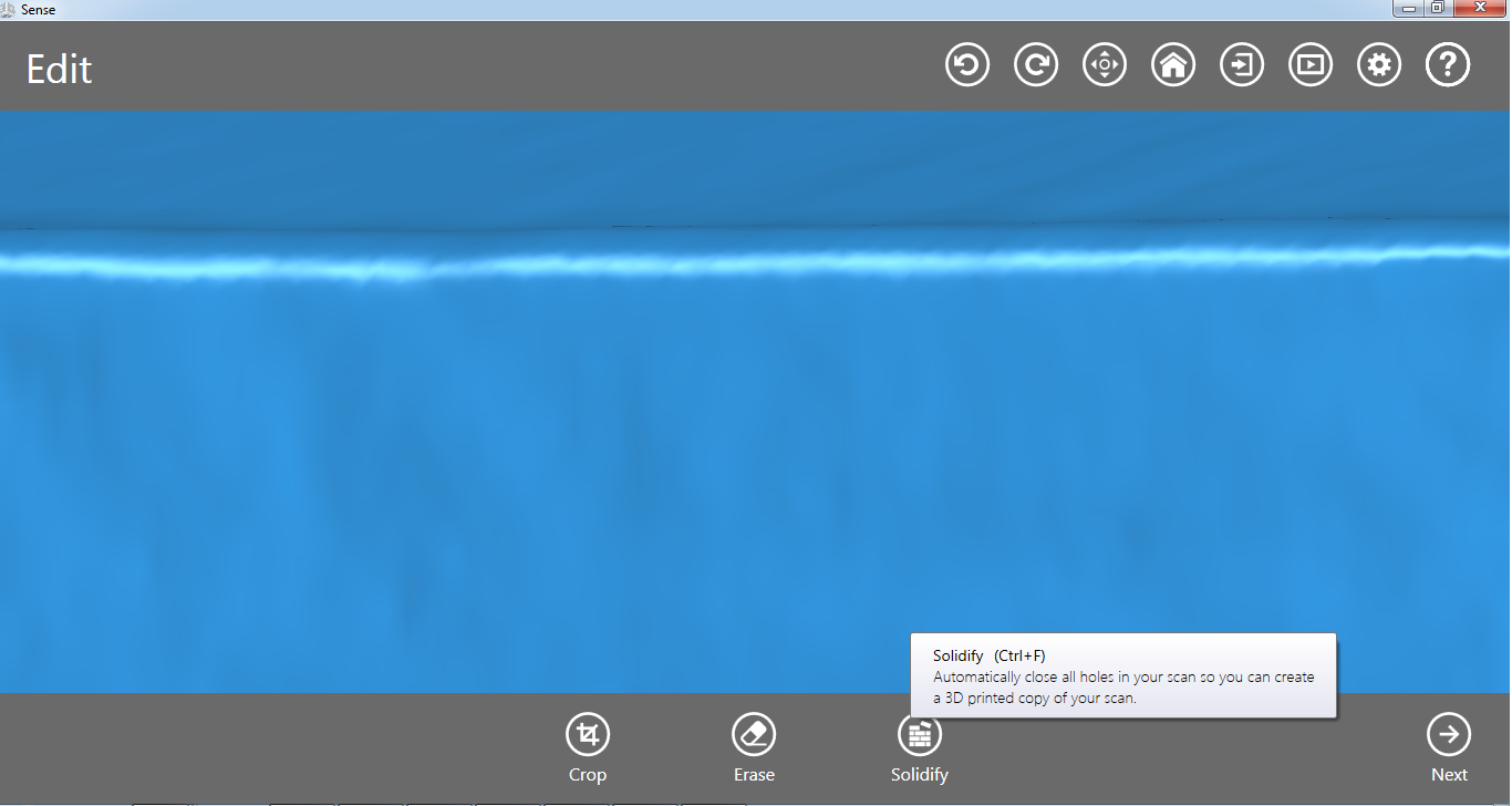
-When I finished scanning I pressed Solidify.
-This is how it looks after I trimmed some parts of it and erased some noise.
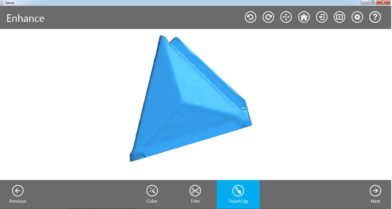
-I saved the file as STL and opened it in Cura.
Downloads
-Chain files-Scan file