WEEK 6
ELECTRONICS DESIGN HELLO WORLD
ELECTRONICS DESIGN HELLO WORLD
This week is all about the software EAGLE and adding some design and new components to the HELLO WORLD schematic. This is bound to be challenging!
So I downloaded the software, we had already saved the download in a file for all students to have easier access. I installed it and selected the freeware option. Next step was to download the helloworld file which I got here.
Because I had already installed it without going through a tutorial I realised I needed to add a library which was through the help of this page. I installed a sparkfun master library from git here.
And continued to work through the tutorial page.
At this junction I actually ended up watching this tutorial online so that I could get to know EAGLE before I started to work on the HELLOWORLD board.
I also checked out something about FRITZING (see second video below).
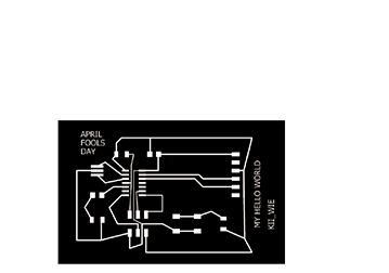
Later we worked on downloading another file from a FABacademy student because we ran into problems with our crystals, so we needed to rapidly prototype and check if it was possible to make a Hello World board that would run without this crystal. The student Katy Levine's here. Next up I went to this page as recommended by our mentor Ohad and looked into using the Arduino as the programmer.
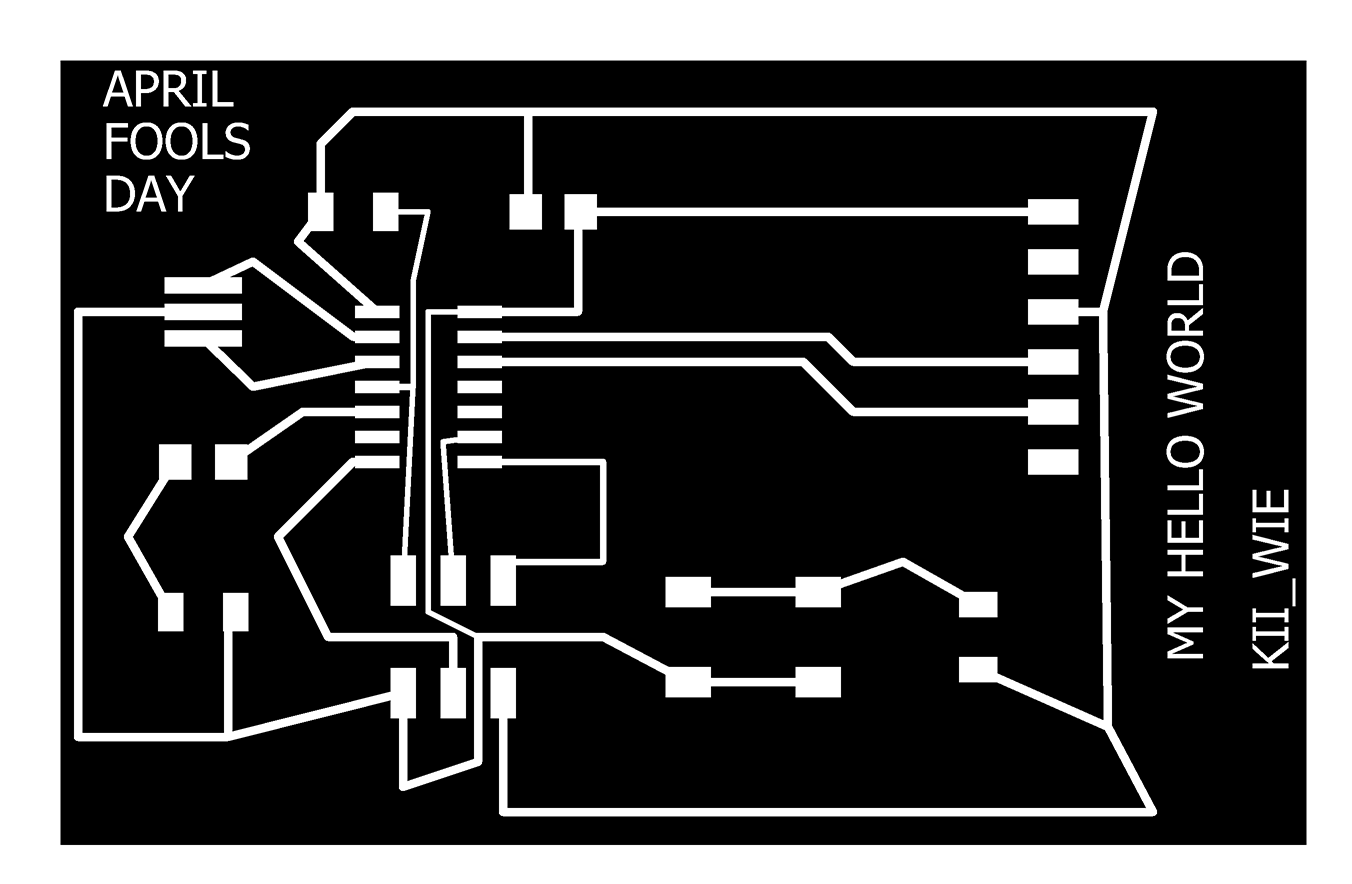
After doing the tutorial (above) it was much easier to work in the EAGLE software and start playing around with making my own board. Here is some of what I did.
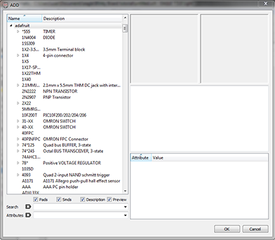
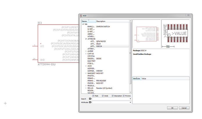
Make sure that you download the FAB.lbr for Eagle which we downloaded and saved into our NAS. You will also need the ADAFRUIT library because the LED is not listed in FAB.lbr (the one that looks exactly the same as the schematic examples).
Then you select the plug tool in the menu on the right and input all the parts you need - this will differ depending on the board you are making / modifying. In the tutorial I watched he was very clear to make the board neat, so therefore I followed the
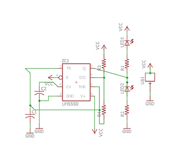
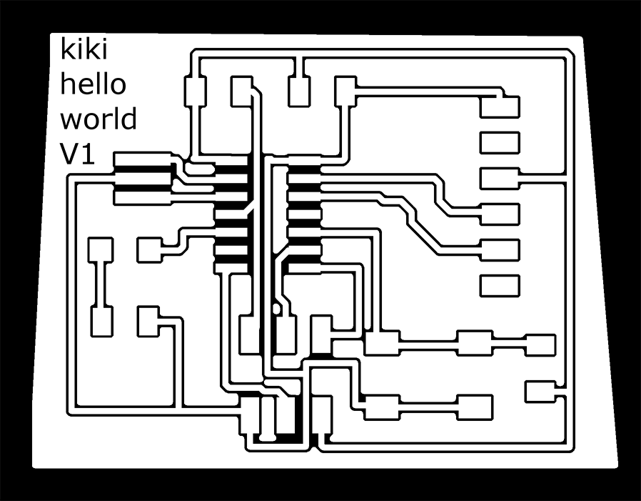
After some researching and lab discussions, we opted to redo the schematic and look at only adding ONE LED, instead of two.
I restarted from scratch because it gets even more confusing trying to revert changes because I had been to the BOARD screen already.
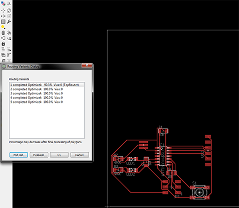
The tutorial said to ratsnest and then automate, which I did for my first attempt. The PROBLEM is that it is really confusing and the lines do not always work - ALSO you do not really learn the functionalities of what goes where and why, so I recommend doing the connections yourself in the board mode.
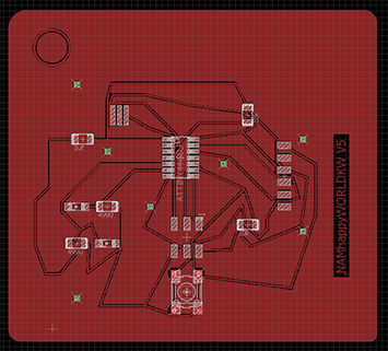
I tried various different options and saw some really cool board designs from other student pages in the archive. At this stage I am keeping it really simple but I do hope to come back to this and experiment further with placing the chips onto an image and connecting them in a visually aligned manner.
I must still mill my board but first I am tasked to lead group work on the final production of any other students board which we will programme and then return back here to make each of our own boards.
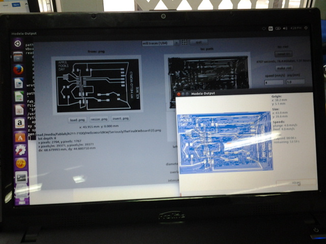
So I
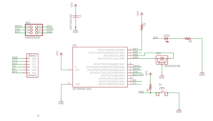
had to solder the Hello World setup the machine and we milled all of our boards(check my page here for settings) and got to soldering the parts on. The parts assembled for our group work are the following:
1. 2 x 10k resistors
2. Attiny44a
3. 4990 resistor
4. 1uf Capacitor
5. A red LED (but you could use any colour)
6. A 3pin (ISP) and 6pin header (FTDI)
7. 20MHZ crystal resonator - WHICH WE DO NOT HAVE SO WE WILL TRY PROGRAM WITHOUT IT! (Thanks for the advice OHAD, lets hope it works :))
Soldering is getting easier the more I practice so putting on the parts went fairly quickly. I watched this video a while ago and this tip comes in handy everytime - ESPECIALLY FOR THE SMALL TINY BITS!
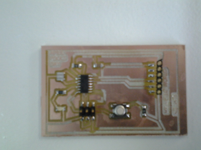
The LED has to have the green marker to GND because it is a diode (LIGHT EMITTING DIODE = LED) and the ATTINY has a circle on the top left which you have to make sure is in the right spot. We wanted to be sure that the parts were correctly placed and after looking at a few students pages we noticed that most people used a MULTIMETER to check. We were not 100% sure how to use it so we watched this video to have a look at how it works.
And there it is! We followed the tutorial of Mr Keith Tan from Fablab Singapore here. Thanks for a good instruction tutorial Keith!
Bjorn helped me to setup the machine because we were all milling our boards in one go and this made the milling time much quicker and all boards were ready for stuffing! The soldering was MUCH quicker than the first time, and my board is also pretty spacious and big i.e I did waste a fair bit of copper which I must not do again! The board is complete and in a week or so I will be programming it!
This is continued on the Embedded Programming page - which is still under construction.