WEEK 4 - ELECTRONICS PRODUCTION

TASK: make an in-circuit programmer.
Objectives:
* PCB (FabISP) fabrication
* PCB Assemblage
* PCB Programming
Software Downloads: Fab Modules,Eagle
1) Fab Modules Tutorial: Generate G-Code
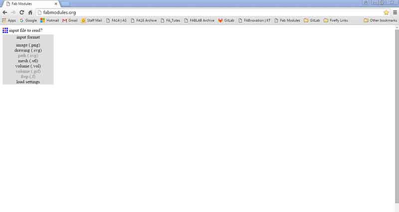
Fab Modules
The fab modules is an online program created to provide a set of software tools for personal fabrication, intended for use with machines common to fab labs.
FabISP
Generally, an ISP is the interface that exists between a computer and a micro-controller. It only translates data and nothing else. The FabISP is an alternative in-system programmer for AVR microcontrollers, designed for production within a FabLab. That is, it allows you to program the microcontrollers on other boards you make, using nothing but a USB cable and 6-pin IDC to 6-pin IDC cable.
Here are some of the critical steps:
Miller model: PCB2020B
a) Access FabISP PNG. files from here. At the bottom of the page look for "traces" and "interior". Next, access Fab Modules page and click "input format" to open PNG. file.
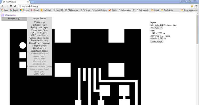
b) To conduct an isolation milling (only milling the traces), leave the "invert image" as default. Next, click "output format" and select G-code (.nc). Change settings to suitable configurations according to machine.
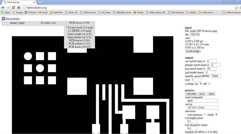
c) Once output format is set, click "process". This is where tool configurations are set. Select "PCB traces 1/64". Next, set the following configurations for traces and board outline to generate nc files:
- Cut Speed: 4mm/s
- Plunge speed: 2mm/s
- Cut depth: 0.18mm
- Tool diameter: 0.4mm
- No. of offsets: 4
- Offset overlap: 50%
- path error: 1.1
- image threshold: 0.5
- sort merge: 1.5
- sort order weight: -1
- sort sequence weight: -1
Once settings are done, click "calculate" to prepare and generate toolpath output file. Next, click "save" to save file (nc. format).
*Refer to the top of page for generated files.
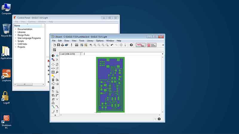
2) Eagles Tutorial: Generate Gerber Code
Gerber Code
Download generated files here:
FABISP.brd .FABISP.brd.lck .FABISP.cmp FABISP.dri FABISP.gpi FABISP.sol FABISP.sts FABISP.plc FABISP.stc
FABISP_interior.brd FABISP_interior.cmp FABISP_interior.dri FABISP_interior.gpi FABISP_interior.plc FABISP_interior.sol FABISP_interior.stc FABISP_interior.sts
Gerber file format serves as de facto standard for PCB image transfer. Gerber codes may be used for machines that do not accept G-code. Gerber codes can be generated using Eagle.
Here are some of the critical steps:
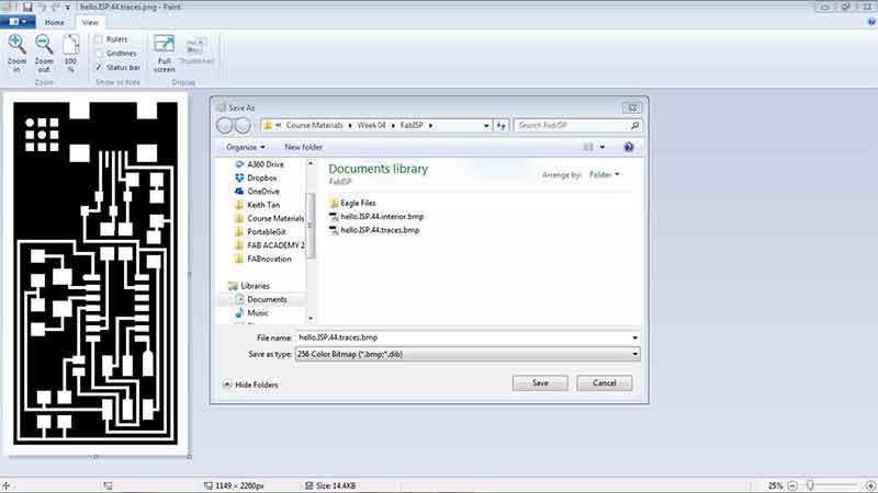
a) Download and setup Eagle. Due to interfacing issues, Eagle is only able to open Bitmap files and can only open Bitmap files with less than 256 colors. This can be resoloved by opening PNG. file in Microsoft Paint and save file as 256 Color Bitmap format. Solution was discovered here.
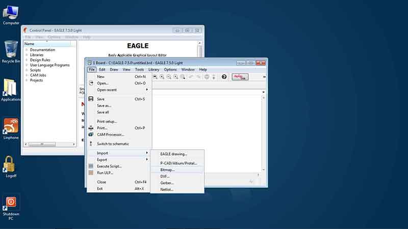
b) Next, open Eagle, go to "File" and click "New" and select "Board". In the Board window, click "file" and select "import" Bitmap to locate saved files. Click "OK" in the pop-up window.
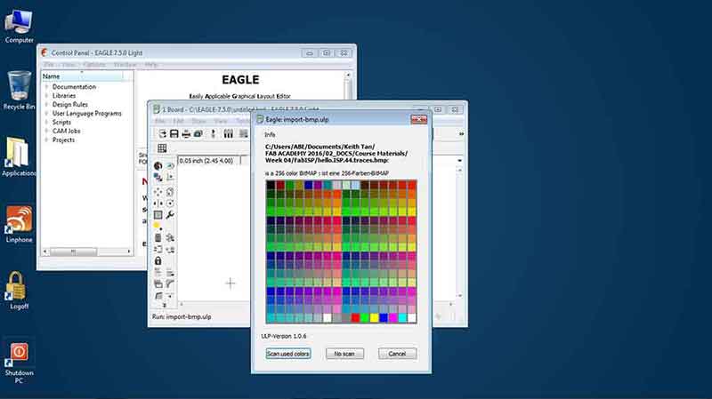
c) Once Bitmap file is selected, a color palatte window will appear. Click "No scan".
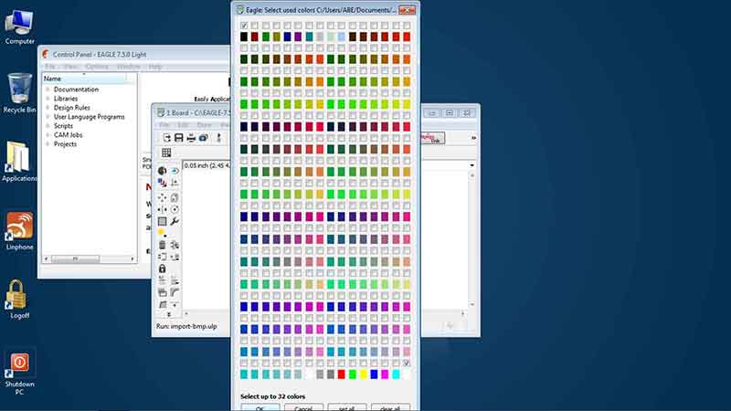
d) Next, another color palatte window will show up. Click the black (top left) and white (bottom right) check boxes and then click "OK".
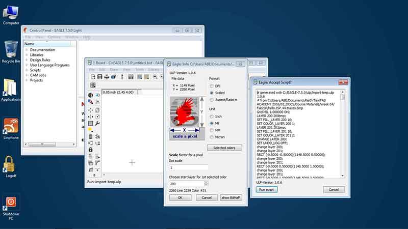
e) In the next pop-up window, click "OK" and click "Run Script" when prompted.
f) Once the traces image is generated, repeat step a to e for the board outline.
g) Here are the final steps to generate gerber codes. Under the Board window, click "File" and open "Job".

h) Select Cam Processor and go to "Cam"> "Open"> "Select job"> Select Gerber274x.cam> "Open". Next, go to "File" again and click "Open" > Select Excellon.cam > and press "Process Job". Once completed, these are some of the files that will be generated from Gerb274x.cam and Excellon.cam (*.cmp , *.gpi, *.plc, *.sol, *.stc, *.sts , *.drd & *.dri).

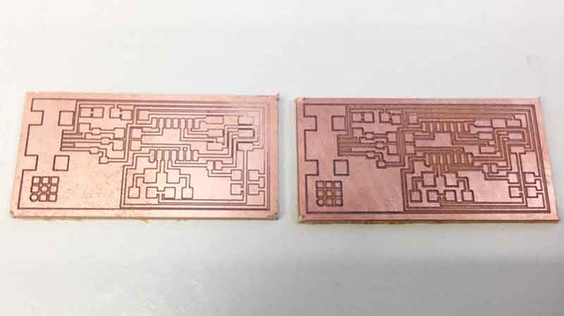
i) Finally, proceed with cutting PCB Board with the generated files. Grooves generated by the cut should be deep enough to isolate the components. As shown in the image below, the board on the right has more isolation quality.
PCB Assemblage
Download image of hello.ISP.44.components
Here are some of the critical steps:
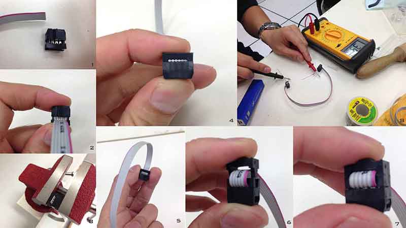
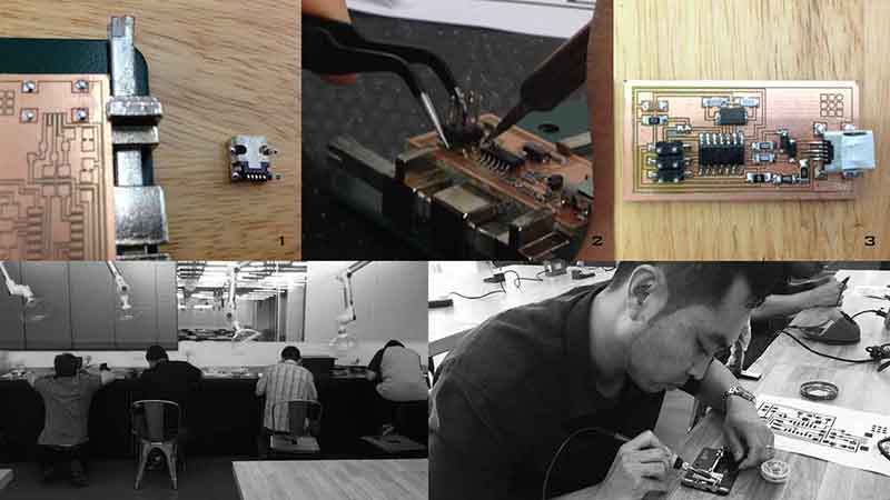
1) Preparation of the Insulation-displacement connector (IDC). Ensure that the wire 1 (red wire) is aligned and connected at the same orientation. Prior to installing the second connection, ensure that the wire is folded into position (refer to image 5 and 6 below) before securing the connector.
2) Follow the downloaded image of hello.ISP.44.components from above to complete solder and assemblage of PCB board. Follow the sequence below to avoid soldering at awkward positions.
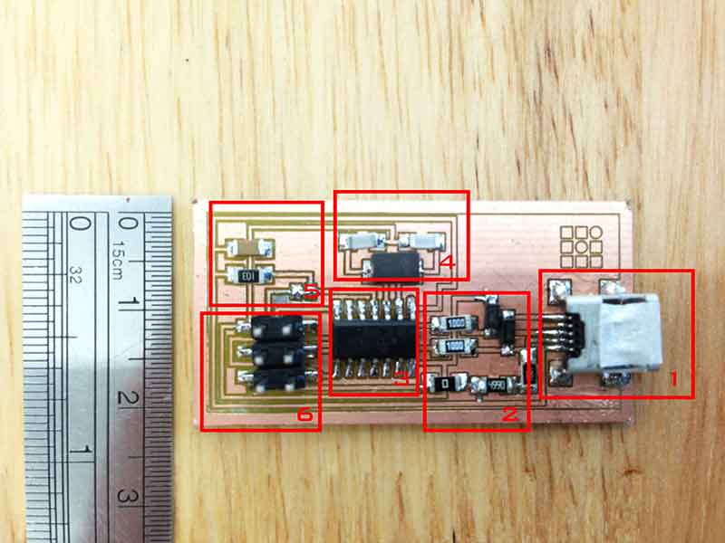
3) Few items to note about assembling the components.
* When soldering USB connector, remember to solder the legs first before the inner pins. This is to prevent it from shifting when soldering the pins (image 1).
* Hardest component to solder besides the USB connector would be the 6 pins connector (image 2). To assemble, ensure there's enough solder on the connection points. Heat the legs of 6 pins connectors to melt the solders to fix it into position. Refer image 3 for completed assembly.
* Practice, practice and practice.
PCB Programming
Tutorial for FabISP Programming
Mac (iOS) Software used: Arduino Crosspack AVR
Firmware required: FabISP Mac.0.8.2 Firmware
Alternate OS installation can be found in Tutorial stated above.
For this particular exercise, a Macbook Pro was used to connect to Arduino UNO and FabISP to process programming and checking connectivity of FabISP board. Here are some critical steps:
1) Ensure IDK connection orientation is accurate. This can be done by making sure that both ends are facing the same direction when connecting wires between Arduino and FabISP.
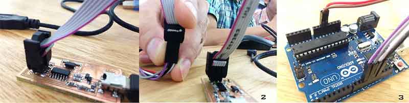
2) Connect wirings between Arduino and FabISP using below:
| Arduino | FabISP |
|---|---|
| 10 | Reset |
| 11 | MOSI |
| 12 | MISO |
| 13 | SCK |
| 5V | VTG |
| GND | GND |
3) Connect FabISP (together with the connected Arduino UNO board) using a USB cable (shown in image 1 above).
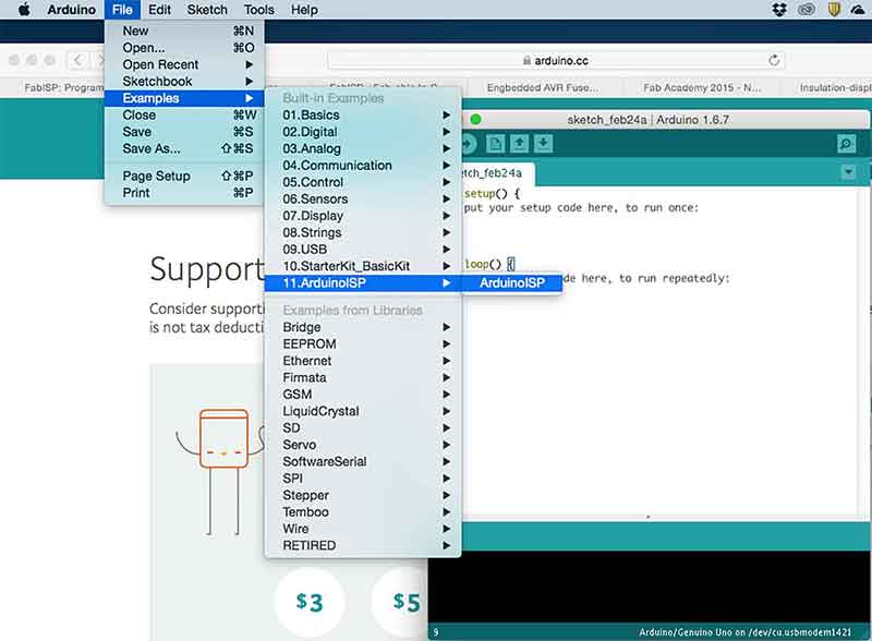
4) Next, open up Arduino Sketch program and go to File> Examples> 11.ArduinoISP> ArduinoISP. Once template is opened, load sketch to Arcuino by clicking the load button (arrow symbol at the top left corner).
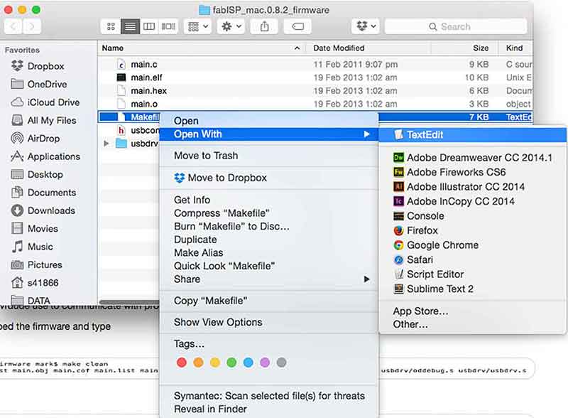
5) Once Arduino UNO is programmed, it's time to program the FabISP using the downloaded firmware for Mac. Unzip the folder (if required), access the folder and right click on the "Makefile" file and open it with TextEdit.
6) In TextEdit, change the commands (Arduino port location) shown below highlighted in yellow. Information of Arduino port location (i.e. /dev/cu.usbmodem...) can be found in Arduino Sketch under Tools> Port. Remember to add a "#" to beginning the line with the "avrisp2" in it to comment it out. Once done, save the file.
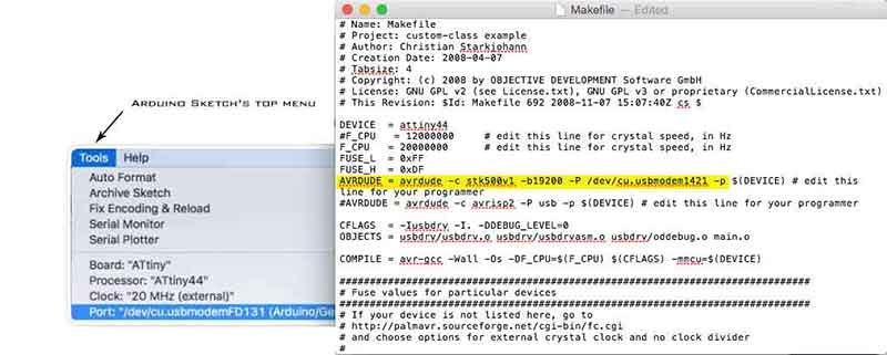
Makefile text below:
MAkefile words.8) Finally, open up terminal to execute a series of commands to program FabISP and to test connections. See text below for process:
[SYSTEM GENERATED MESSAGES] Generating public/private rsa key pair.
cd Desktop [ACCESS THE FIRMWARE DIRECTORY]
ls [LIST CONTENT TO SEARCH FOR FIRMWARE FOLDER]
cd fabISP_mac.0.8.2_firmware [ACCESS FOLDER]
ls [LIST CONTENT TO ENSURE Makefile DOCUMENT EXISTS]
make clean [EXECUTE COMMAND]

[SYSTEM GENERATED INFORMATION]
rm -f main.hex main.lst main.obj main.cof main.list main.map main.eep.hex main.elf *.o usbdrv/*.o main.s usbdrv/oddebug.s usbdrv/usbdrv.s
ABE-MB41866-1:fabISP_mac.0.8.2_firmware s41866$ make hex
avr-gcc -Wall -Os -DF_CPU=20000000	 -Iusbdrv -I. -DDEBUG_LEVEL=0 -mmcu=attiny44 -c usbdrv/usbdrv.c -o usbdrv/usbdrv.o
avr-gcc -Wall -Os -DF_CPU=20000000	 -Iusbdrv -I. -DDEBUG_LEVEL=0 -mmcu=attiny44 -x assembler-with-cpp -c usbdrv/usbdrvasm.S -o usbdrv/usbdrvasm.o
avr-gcc -Wall -Os -DF_CPU=20000000	 -Iusbdrv -I. -DDEBUG_LEVEL=0 -mmcu=attiny44 -c usbdrv/oddebug.c -o usbdrv/oddebug.o
avr-gcc -Wall -Os -DF_CPU=20000000	 -Iusbdrv -I. -DDEBUG_LEVEL=0 -mmcu=attiny44 -c main.c -o main.o
main.c:88:13: warning: always_inline function might not be inlinable [-Wattributes]
 static void delay ( void )
             ^
avr-gcc -Wall -Os -DF_CPU=20000000	 -Iusbdrv -I. -DDEBUG_LEVEL=0 -mmcu=attiny44 -o main.elf usbdrv/usbdrv.o usbdrv/usbdrvasm.o usbdrv/oddebug.o main.o
rm -f main.hex main.eep.hex
avr-objcopy -j .text -j .data -O ihex main.elf main.hex
avr-size main.hex
   text	   data	    bss	    dec	    hex	filename
      0	   2002	      0	   2002	    7d2	main.hex
ABE-MB41866-1:fabISP_mac.0.8.2_firmware s41866$ make fuse
avrdude -c stk500v1 -b19200 -P /dev/cu.usbmodem1421 -pattiny44  -U hfuse:w:0xDF:m -U lfuse:w:0xFF:m

avrdude: AVR device initialized and ready to accept instructions

Reading | ################################################## | 100% 0.02s

avrdude: Device signature = 0xffffff (retrying)

Reading | ################################################## | 100% 0.02s

avrdude: Device signature = 0xffffff (retrying)

Reading | ################################################## | 100% 0.02s

avrdude: Device signature = 0xffffff
avrdude: Yikes!  Invalid device signature.
         Double check connections and try again, or use -F to override
         this check.


avrdude done.  Thank you.


make fuse [EXECUTE COMMAND]

[SYSTEM GENERATED INFORMATION]
avrdude -c stk500v1 -b19200 -P /dev/cu.usbmodem1421 -pattiny44  -U hfuse:w:0xDF:m -U lfuse:w:0xFF:m

avrdude: AVR device initialized and ready to accept instructions

Reading | ################################################## | 100% 0.03s

avrdude: Device signature = 0x1e9207
avrdude: reading input file "0xDF"
avrdude: writing hfuse (1 bytes):

Writing | ################################################## | 100% 0.01s

avrdude: 1 bytes of hfuse written
avrdude: verifying hfuse memory against 0xDF:
avrdude: load data hfuse data from input file 0xDF:
avrdude: input file 0xDF contains 1 bytes
avrdude: reading on-chip hfuse data:

Reading | ################################################## | 100% 0.01s

avrdude: verifying ...
avrdude: 1 bytes of hfuse verified
avrdude: reading input file "0xFF"
avrdude: writing lfuse (1 bytes):

Writing | ################################################## | 100% 0.01s

avrdude: 1 bytes of lfuse written
avrdude: verifying lfuse memory against 0xFF:
avrdude: load data lfuse data from input file 0xFF:
avrdude: input file 0xFF contains 1 bytes
avrdude: reading on-chip lfuse data:

Reading | ################################################## | 100% 0.01s

avrdude: verifying ...
avrdude: 1 bytes of lfuse verified

avrdude: safemode: Fuses OK (H:FF, E:DF, L:FF)

avrdude done.  Thank you.


make program [EXECUTE COMMAND]

[SYSTEM GENERATED INFORMATION]
avrdude -c stk500v1 -b19200 -P /dev/cu.usbmodem1421 -pattiny44  -U flash:w:main.hex:i

avrdude: AVR device initialized and ready to accept instructions

Reading | ################################################## | 100% 0.02s

avrdude: Device signature = 0x1e9207
avrdude: NOTE: "flash" memory has been specified, an erase cycle will be performed
         To disable this feature, specify the -D option.
avrdude: erasing chip
avrdude: reading input file "main.hex"
avrdude: writing flash (2002 bytes):

Writing | ################################################## | 100% 2.89s

avrdude: 2002 bytes of flash written
avrdude: verifying flash memory against main.hex:
avrdude: load data flash data from input file main.hex:
avrdude: input file main.hex contains 2002 bytes
avrdude: reading on-chip flash data:

Reading | ################################################## | 100% 1.44s

avrdude: verifying ...
avrdude: 2002 bytes of flash verified

avrdude: safemode: Fuses OK (H:FF, E:DF, L:FF)

avrdude done.  Thank you.

avrdude -c stk500v1 -b19200 -P /dev/cu.usbmodem1421 -pattiny44  -U hfuse:w:0xDF:m -U lfuse:w:0xFF:m

avrdude: AVR device initialized and ready to accept instructions

Reading | ################################################## | 100% 0.02s

avrdude: Device signature = 0x1e9207
avrdude: reading input file "0xDF"
avrdude: writing hfuse (1 bytes):

Writing | ################################################## | 100% 0.01s

avrdude: 1 bytes of hfuse written
avrdude: verifying hfuse memory against 0xDF:
avrdude: load data hfuse data from input file 0xDF:
avrdude: input file 0xDF contains 1 bytes
avrdude: reading on-chip hfuse data:

Reading | ################################################## | 100% 0.01s

avrdude: verifying ...
avrdude: 1 bytes of hfuse verified
avrdude: reading input file "0xFF"
avrdude: writing lfuse (1 bytes):

Writing | ################################################## | 100% 0.01s

avrdude: 1 bytes of lfuse written
avrdude: verifying lfuse memory against 0xFF:
avrdude: load data lfuse data from input file 0xFF:
avrdude: input file 0xFF contains 1 bytes
avrdude: reading on-chip lfuse data:

Reading | ################################################## | 100% 0.01s

avrdude: verifying ...
avrdude: 1 bytes of lfuse verified

avrdude: safemode: Fuses OK (H:FF, E:DF, L:FF)

avrdude done.  Thank you.

[PROGRAMMING COMPLETED]
REFLECTIONS
Being able to complete a production of a circuit board was eye opening. The most difficult process is soldering the hairline components which will take a lot more practice to achieve a more presentable standards. Besides soldering, troubleshooting errors on the board can be hair-pulling experience as there are several components to check for continuity. All-in-all, it's been an amazing week.

Related Projects