Output devices
Have you:
- Described your design and fabrication process using words/images/screenshots.
- Explained the programming process/es you used and how the microcontroller datasheet helped you.
- Outlined problems and how you fixed them
Described your design and fabrication process using words/images/screenshots.
I decided to modify Neil's
hello.stepper.bipolar
board to control a step motor from Arduino.
BOM
- (02) A4953 drivers
- (02) Capacitor 0.1uF
- (02) Capacitor 10uF
- (03) Resistor 0 ohm (jumper)
- (02) Connector 2x1
- (01) Connector 4x1
- (01) Connector Molex 4x1
A4953 is a Full-Bridge DMOS PWM Motor Drivers capable of peak output currents to ±2 A and operating voltages to 40 V.
I'm going to work with a Bipolar Stepper Motor so I need to use (02) A4953.
Extract from Datasheet:
"Input terminals are provided for use in controlling the speed and direction of a DC motor with externally applied PWM control signals.
Internal synchronous rectification control circuitry is provided to lower power dissipation during PWM operation."
It is recommended to use heat sinks as they tend to heat up.
You can download datasheet from
Here
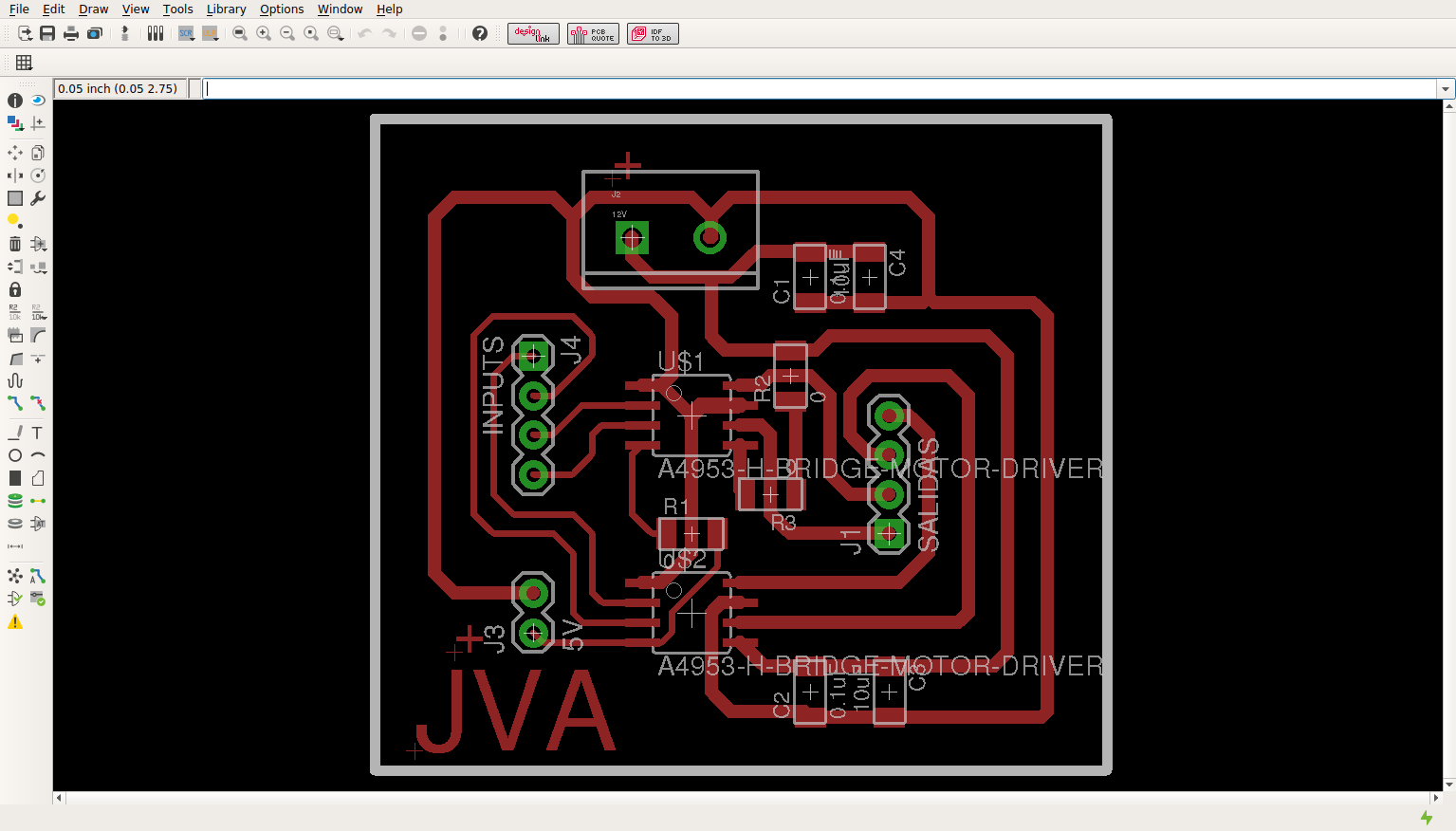
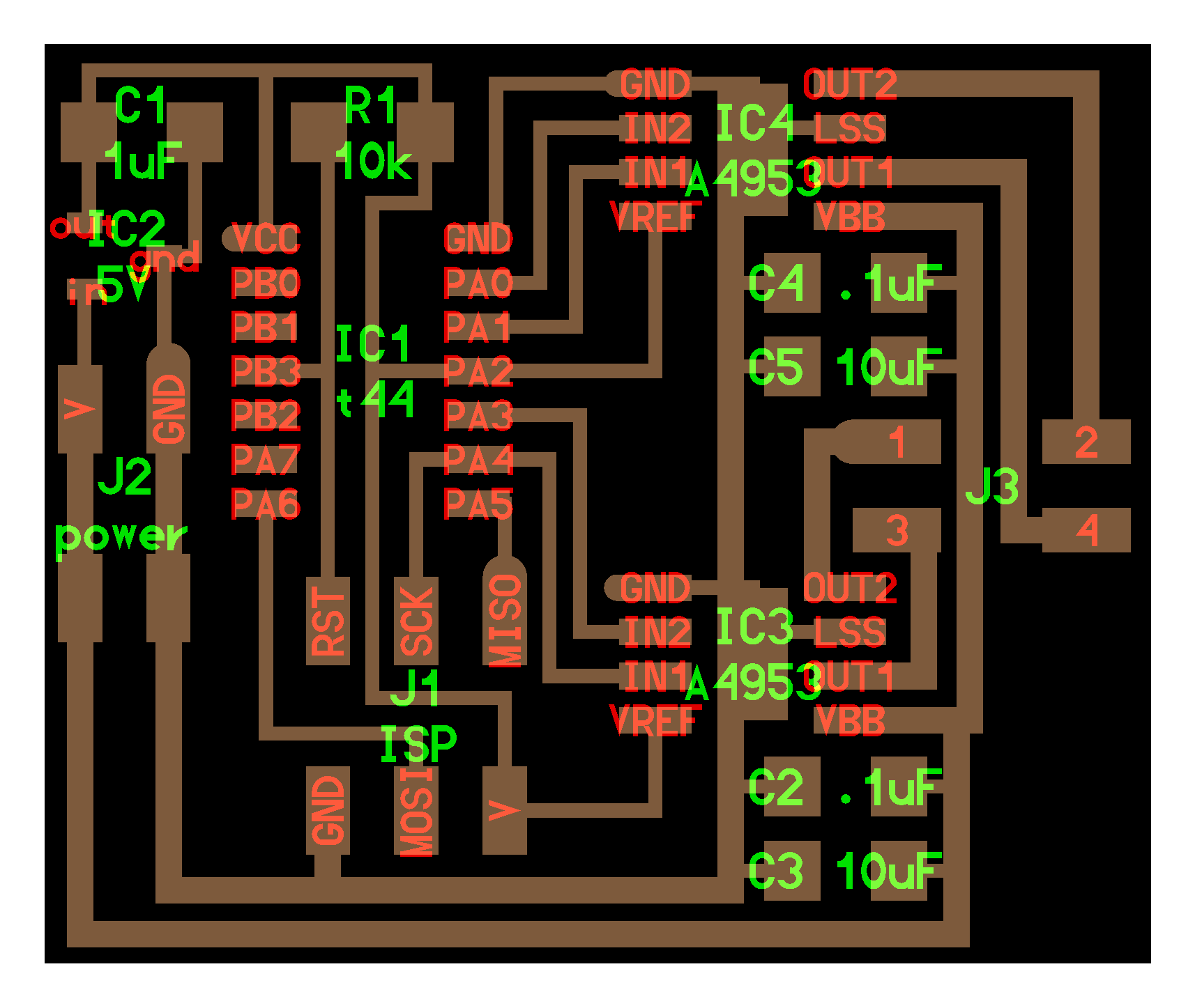
By using the "Eagle" software I designed my schematic circuit for controlling a stepper motor.
This printed board module can function as stepper motor control for any development board based on microcontroller.

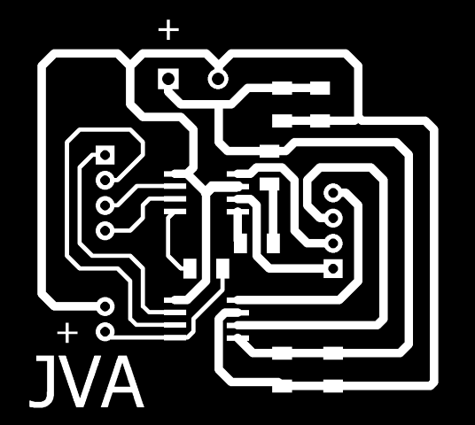
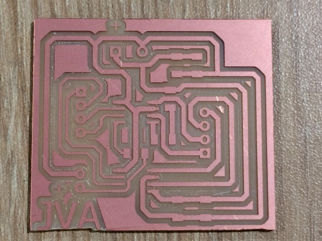
Files for milling with the machine.

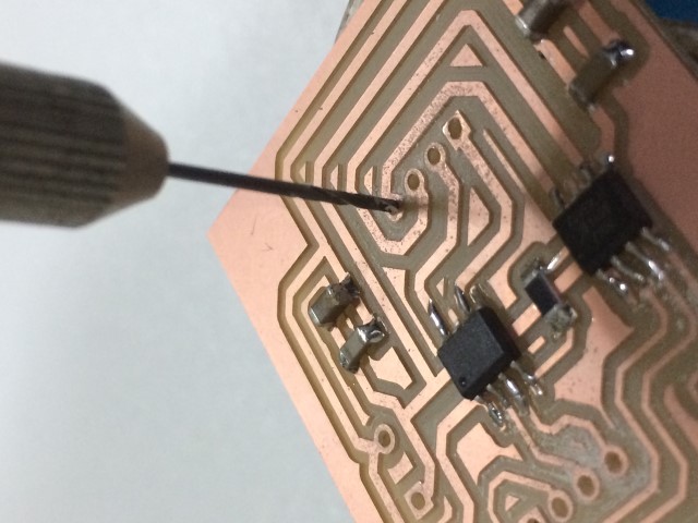
After the manufacture of the printed board to be cleaned and welded components.
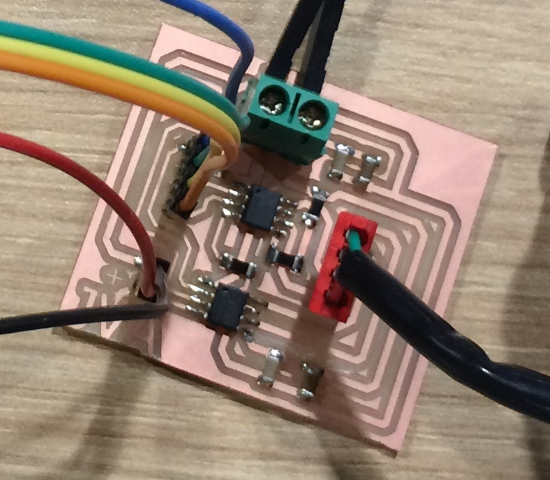
Explained the programming process/es you used and how the microcontroller datasheet helped you.
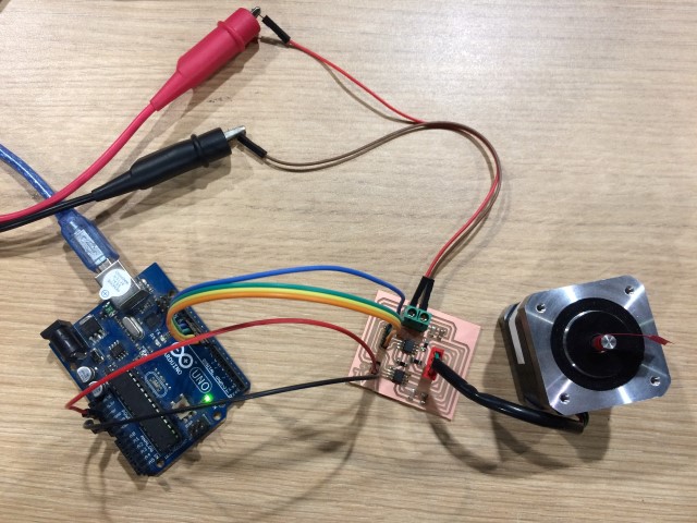
Make the following connections:
- Connect the Arduino module to the PC.
- Connect 5V and GND in the respective connector.
- Connect any of the PWM outputs.
- Connect an external source in the terminal (12V @ 1A)
Write the following code in the Arduino IDE:
										#include "Stepper.h"


										const int stepsPerRevolution = 200;  // change this to fit the number of steps per revolution

										// for your motor


										// initialize the stepper library on pins 8 through 11:

										Stepper myStepper(stepsPerRevolution, 8, 9, 10, 11);


										int stepCount = 0;         // number of steps the motor has taken


										void setup() {

											// initialize the serial port:

											Serial.begin(9600);

										}


										void loop() {

											// step one step:

											stepCount = Serial.read();


											myStepper.step(stepCount);

											Serial.print("steps:");

											Serial.println(stepCount);


											delay(500);

										}
Here is a video of the operation of the application.
Outlined problems and how you fixed them
I had problems when designing the pcb, I missed connect GND signals of the motor driver. I corrected my design and I returned to make the pcb.