Electronics design
Have you:
- Shown your process using words/images/screenshots
- Explained problems and how you fixed them
- Done fabbercise today
- Included original design files (Eagle, KiCad, Inkscape whatever)
Shown your process using words/images/screenshots
- Redraw the echo hello-world board
- Add (at least) a button and LED (with current-limiting resistor)
- Check the design rules, and make it
- Extra credit: simulate its operation
It is recommended to use the FabLab library for Eagle, download from Here. Select "Freeware" option when Eagle is installed.
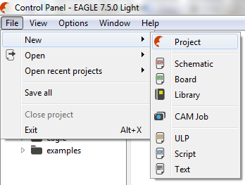
Step 1: Create a new Project.
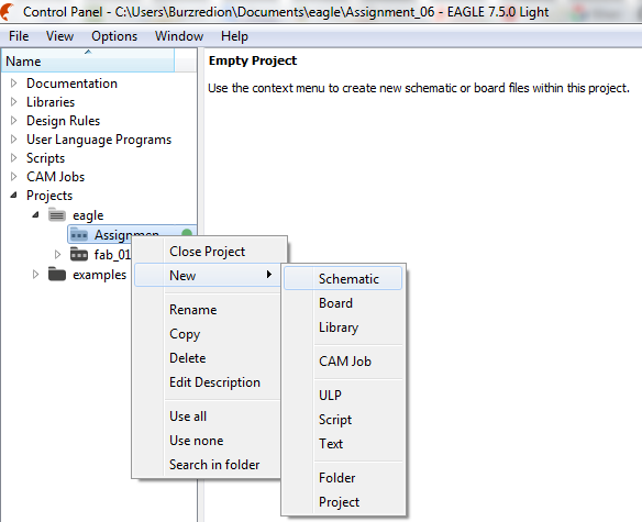
Step 2: Create a new Schematic.
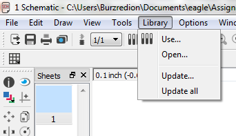
Step 3: Add fab.lbr library
Step 4: Add the following components:
- (01) ATTINY44-SSU
- (01) CAP-US1206FAB
- (04) RES-US1206FAB
- (02) LEDFAB1206
- (01) 6MM_SWITCH6MM_SWITCH
- (01) RESONATOR
- (01) FTDI-SMD-HEADER
- (01) AVRISPSMD
- VCC
- GND
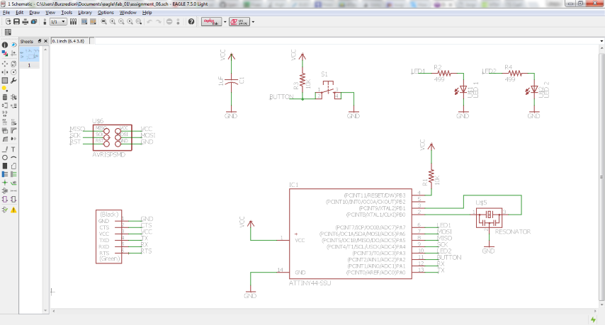
I recommend using the NAME tool for naming the wires and the LABEL tool to show their names on the schematic.
Step 6: PCB design.
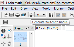
Press the "Generate/switch to board" option.
A PCB file is generated with the footprints of the components. You should order the components and then wire
The following is recommended:
- Work on the Top layer.
- Grid: 0.025"
- Width: 0.0116"
- Clearance: 16mils
- At the end, add Copper Pours as shown in the tutorial of Sparkfun
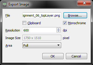
Step 7: Export PCB.
You must export the TOP and DIMM layers separately, File>>Export>>Image.
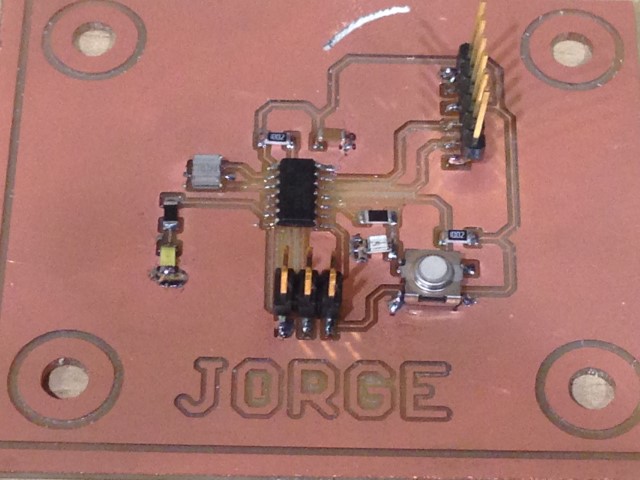
Step 8: Milling the PCB
Follow the same steps that were used in the Assignment 04.
Programming
You can program the PCB using the Arduino IDE. The following is required:- FabISP programmer
- FTDI cable
FabISP driver
FTDI driver
Download Arduino IDE from Here.
Install support for "Attiny" controllers. I recommend following this Tutorial, it is compatible with the current version: 1.6.7.
Code to toggle LEDs by pressing the push button:
										void setup() {

											// put your setup code here, to run once:

											pinMode(3, OUTPUT);

											pinMode(7, OUTPUT);

											pinMode(2, INPUT);

										}


										void loop() {

											// put your main code here, to run repeatedly:

											if(digitalRead(2) == LOW)

											{

												digitalWrite(3, HIGH);

												digitalWrite(7, LOW);

											}else

											{

												digitalWrite(3, LOW);

												digitalWrite(7, HIGH);

											}

										}
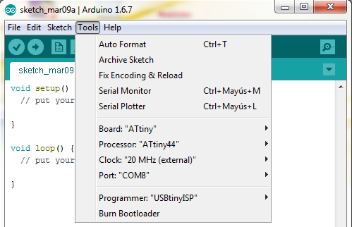
- Board: "ATtiny"
- Processor: "ATtiny44"
- Clock: "20MHz (external)"
- Programmer: "USBtinyISP"
Turn up the code and test PCB. You will see that an LED is on and the other off, pressing the pushbutton the LED goes on and off is turned on.
Simulating
To simulate the circuit use the following software:- Proteus: to design and simulate the schematic operation..
- Atmel Studio: to write the code that runs the simulation.
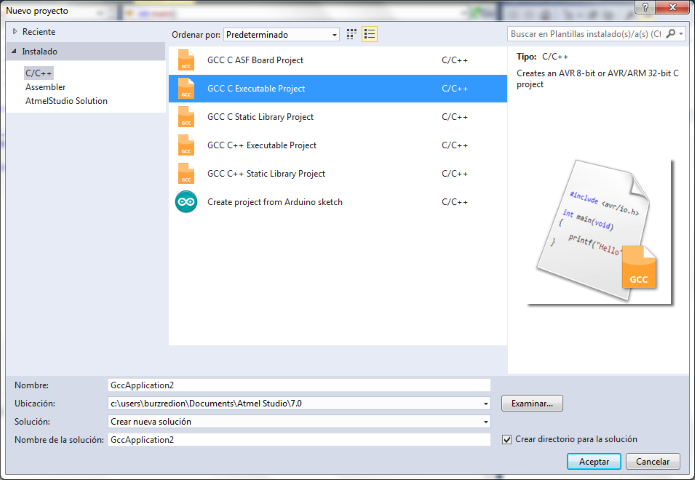
File>>New>>Project
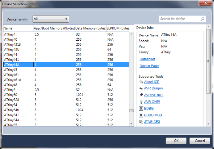
Choose the device
Step 2: Type the following code
#define F_CPU 20000000UL
#include
#include
int main() {
DDRA |= (1 << PA3)|(1 << PA7);
DDRA &= ~(1 << PA2);
while (1)
{
if((PINA & (1<
PORTA |= (1 << PORTA3);
PORTA &= ~(1 << PORTA7);
}
else
{
PORTA &= ~(1 << PORTA3);
PORTA |= (1 << PORTA7);
}
}
}
<Step 3: Create a new project on Proteus
File>>New Project
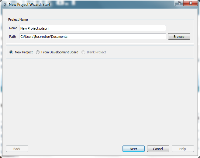
Create a schematic from the selected template
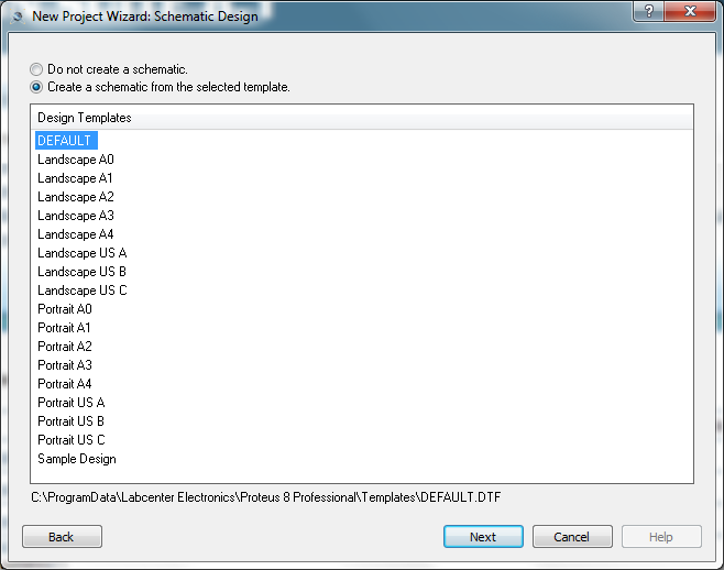
Do not create a PCB layout
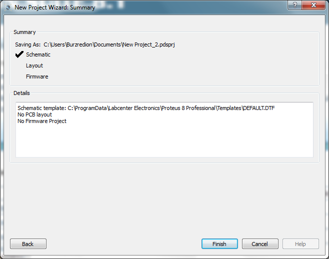
No Firmware Project
New Project Wizard: Summary
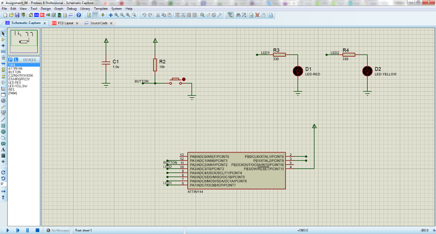
Place the parts:
- (01) ATTINY44
- (01) BUTTON
- (01) CAPACITOR
- (01) LED-RED
- (01) LED-YELLOW
- (03) RES
Edit component ATTINY44, double-click and configure
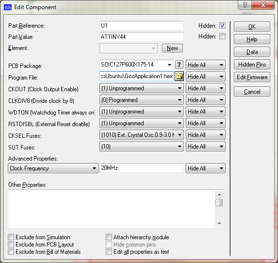
Finally, run the simulation. You can see if you push switch the LED-RED and LED-YELLOW toggle.
Explained problems and how you fixed them
- I had problems with Interior (mill out) PNG, I used "Paint" in Windows to invert the colors, but two sides were too thin. I did it again and enlarged the borders.