Week 7: Computer-controlled machining
One of the things I wanted for this Fab Academy is to use more the CNC milling machine. Both the modela for PCB manufacturing and the big one for making big things! We were lucky to have a big (1600x1000mm) and relatively powerful (130W) laser machine that allowed us to cut 10mm of MDF, plywood and PMMA at a decent speed, between 400 and 600 mm/min. That allowed our members to protoype big things just using the laser cutter. But after about 1800 hours of use, it's not cutting 10mm as used to be.
From my experience and conversations with other Fab Labs and other digital fabrication laboratories, the milling machine is not as friendly as a laser cutter can be. First thing is the tool itslef, while the laser tube degrades over a few thousand of hours and the laser beam doesn't apply any force to the material, the life of a mill can go from seconds (if you break it as you take it outside of its box) to several hours, but most importantly, there are big forces being applied to the material by the movement of the mill bit.
So we had lot of members completely autonomous when using the laser cutter, but none with the milling machine, that we used most for projects developed by us for artist residencies or other collaborations. Another thing is that mills aren't cheap, and good mills are quite expensive. One 6mm 2 flute universal end mill costs around 15€ (VAT incl.) and it may not seem much, but a good supply of mills to perform different operations can sum up 500-600€ easily including some duplicates so you don't see yourself without a certain tool in case of a break. Even a good starter kit, with 5 or 6 mills for most purpouse can cost up to 100-120€. So it is understandable that we were a bit reticent about users handling our mills and that the users didn't make that kind of investment prior to really know how to operate the machine.
At this point I must confess myself as "China-supplied". Because one of my main interests in this fab movement is the democratization of technologies and cost has a lot to do with that. I've been buying little gadgets and DIY supplies from China for around 8 years, first at dealextreme.com then ebay.es from international sellers, and now most of what I buy from overseas comes from aliexpress.com . I hope Neil won't read this but I believe that would be interesting to have an alternate Fab Inventory with items from aliexpress.com which is truly global. Recently I've made a secondary aliexpress.com account just to put Fab items, from machines to electronic components, and the first cart I've filled, with a big laser, a big CNC, an FDM printer, an SLA printer, a cutter plotter, oscilloscope, solder stations, power supplies, hand tools, mill bits, and whatever I was able to find on aliexpress, and the total car was less than 10000€! which is not really true, cause you'll have to add taxes and other costs, but a base price for that starting at 10k€ it's just amazing.
But my confession took a whole paragraph and did not relate to the assignment, here it comes, about a month prior to the "make something big" assignment I took a mill bit search at aliexpress.com, and found prices so low that it was just not logic to to get some bits and test them. I ended up buying 6 different mills (6mm end 2, 3 and 4 flutes, 6mm ball, 4mm 1 flute, 3mm 2flutes) for just 8€! And what if they break or get dull sooner than the good ones? nothing, I think they're still a great option for practising. I dind't fully test them, but 90% of the cutting for this assignmnet was made with the 2 flute 6mm end mill and wear seems similar to a good one, still not enough use to get a solid conclusion.
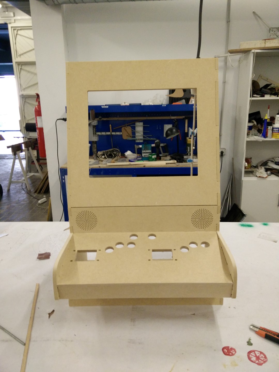
As for the actual assignment, I wanted to go with one of the ideas I got on week 1 about a final project: The WallCade. As someone who likes video games, I've always wanted to have an arcade cabinet but it is difficult to have that spare space available living in a flat. So the alternative is usually to make what is known as a bar-top which is reduced scale cabinet to place over a table. I didn't liked that because it's more like having controls to a tablet than to play a real arcade, so I came up with an idea: a wall cabinet. A cabinet you would hang on the wall. First thing was to look online for it and there were some examples but to my surprise not so many DIY builds or projects. I've discarded it for my final project because of the simplicity of just cutting the cabinet and then attach electronics, but it's now being considered as an option for the final project.
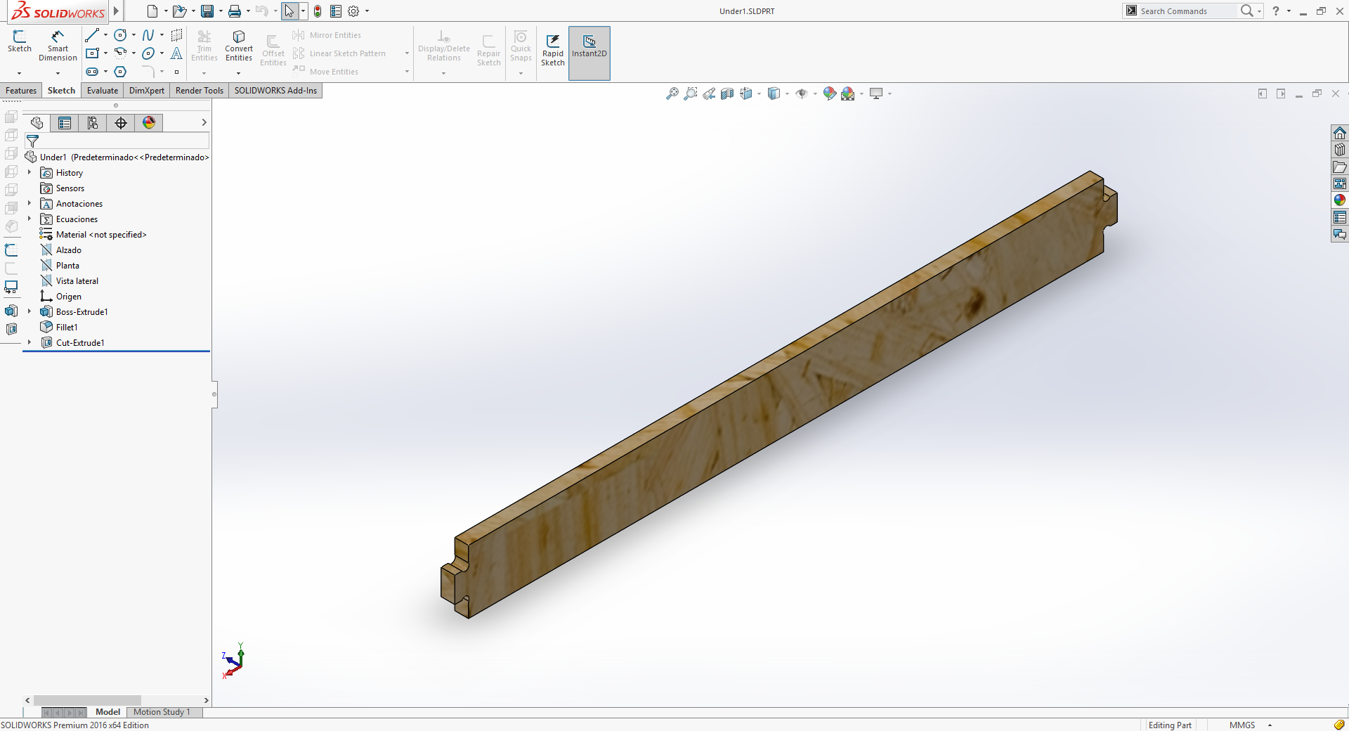
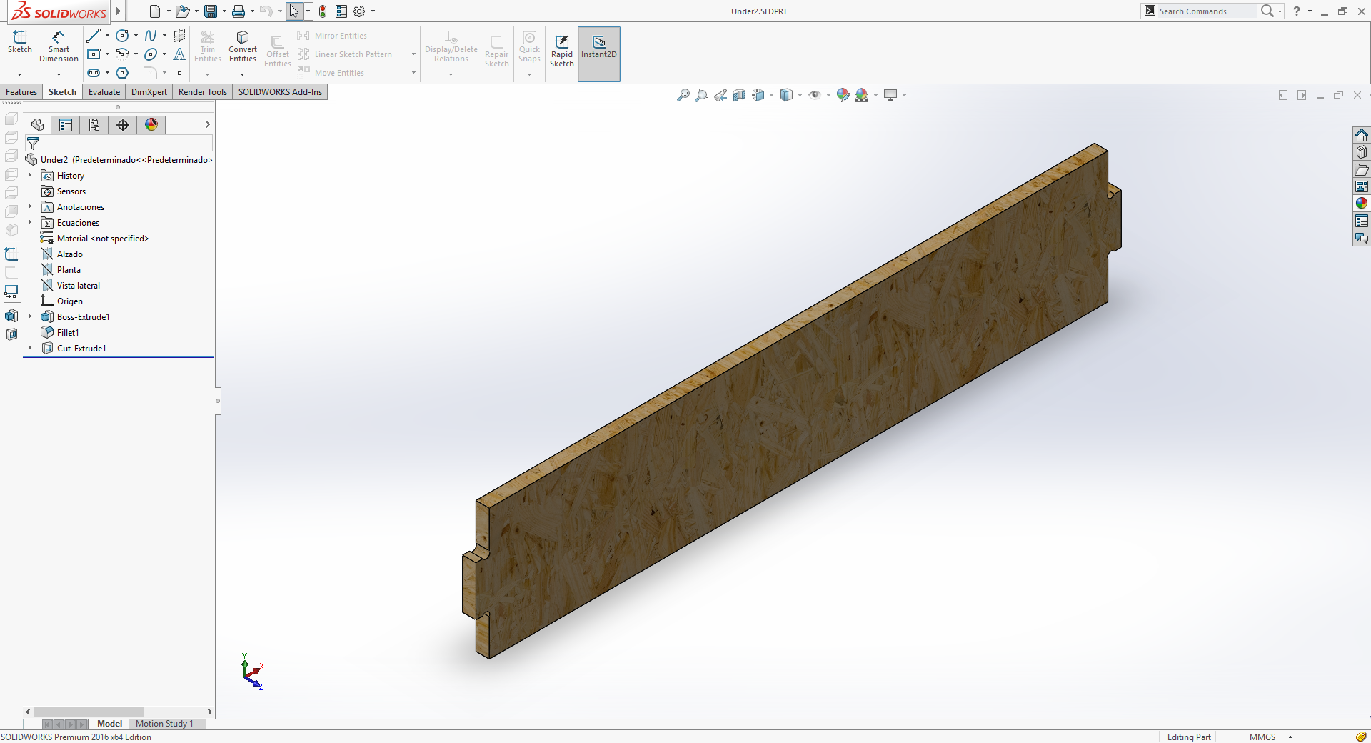
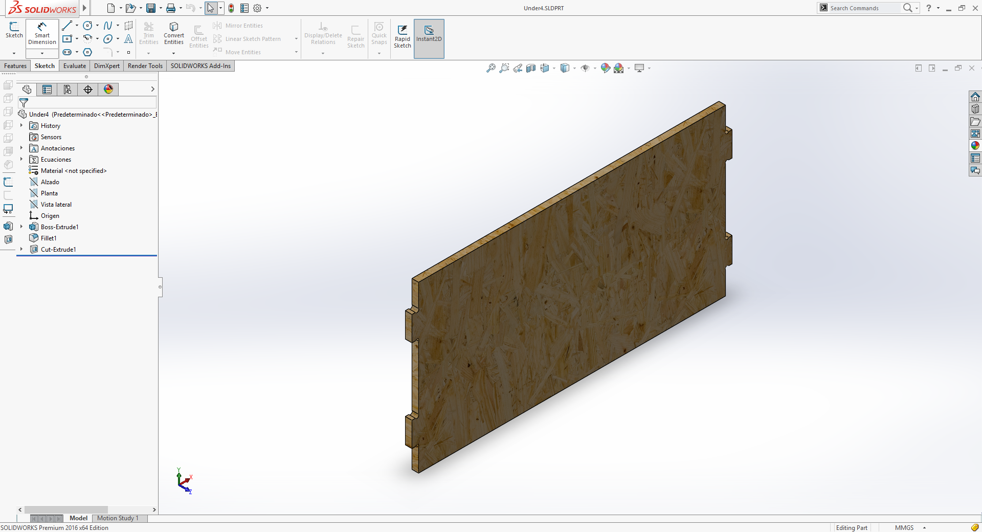
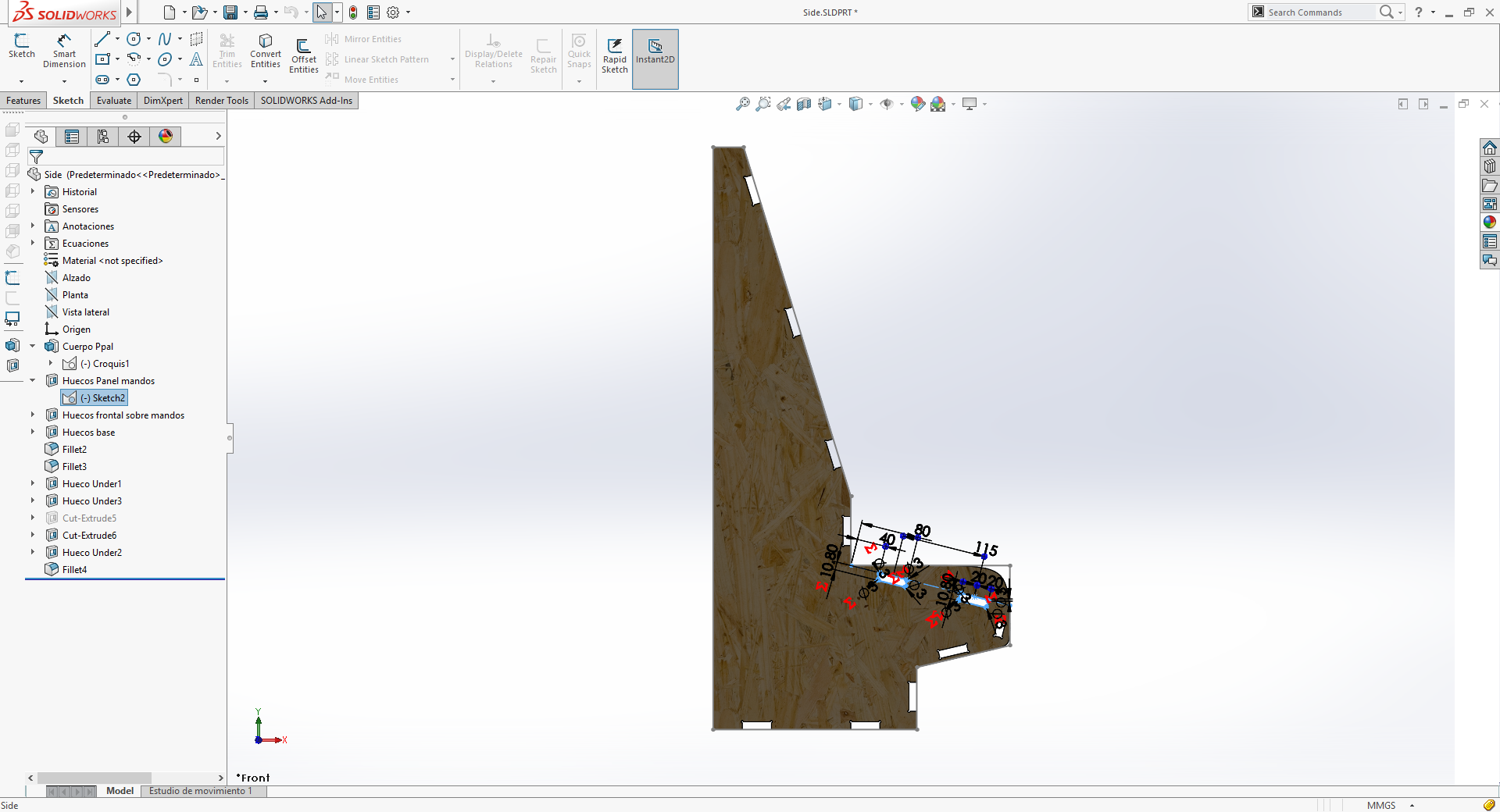
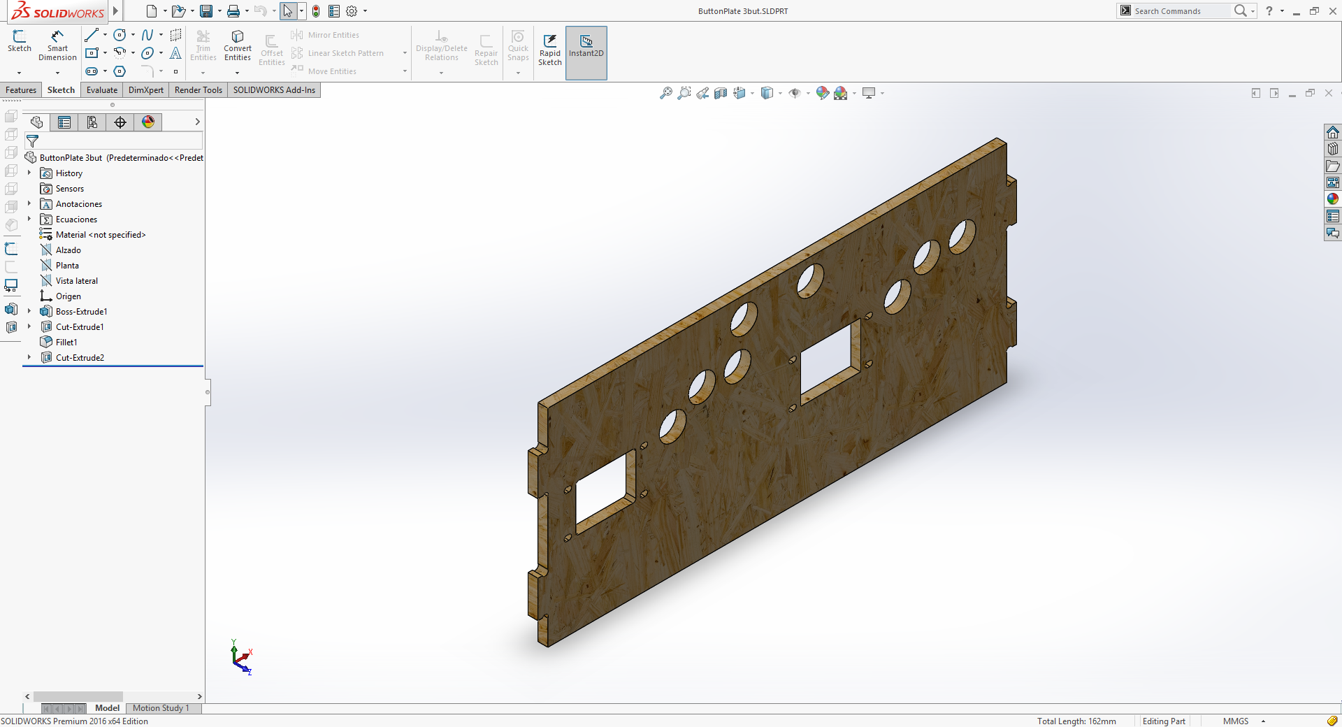
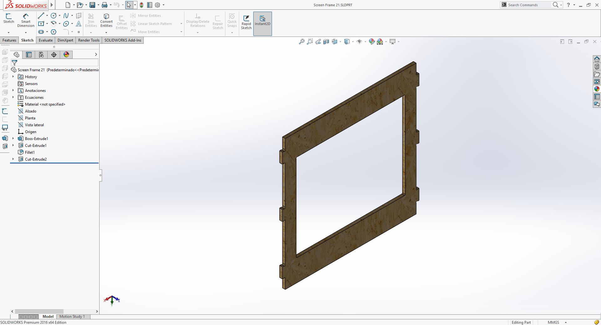
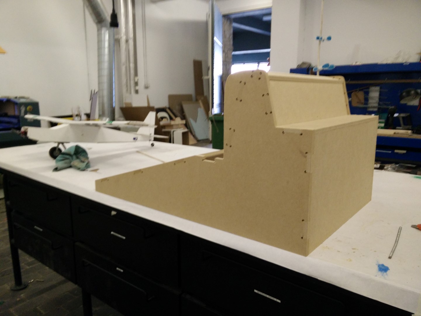
So first thing was to design it. I'm gonna keep using SolidWorks for this asignment too. For the first design, I've imported a side schematic picture of a full size cabinet, defined some measures and started designing from that base. The first part to design was the side panel, from that I will just need to close it with other panels including screen and controls panels.
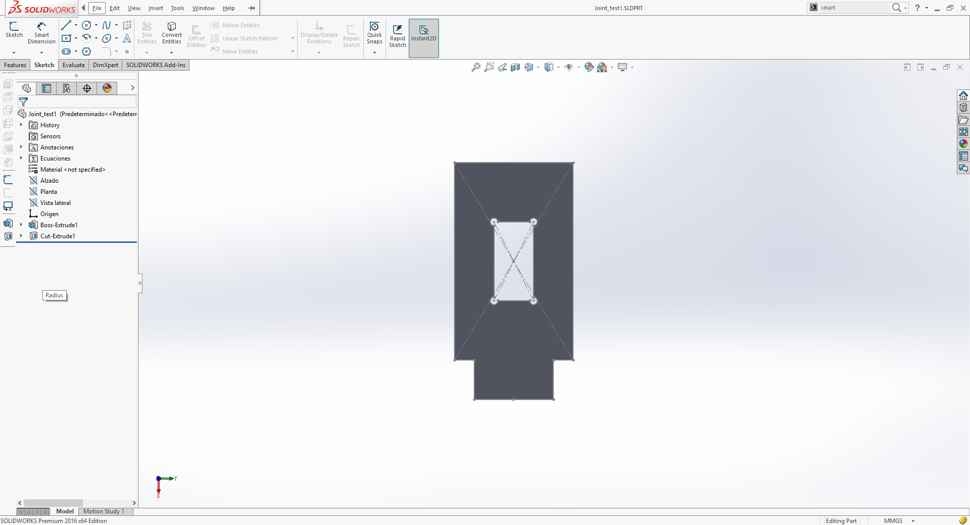
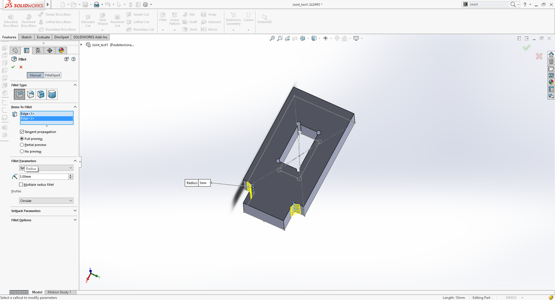
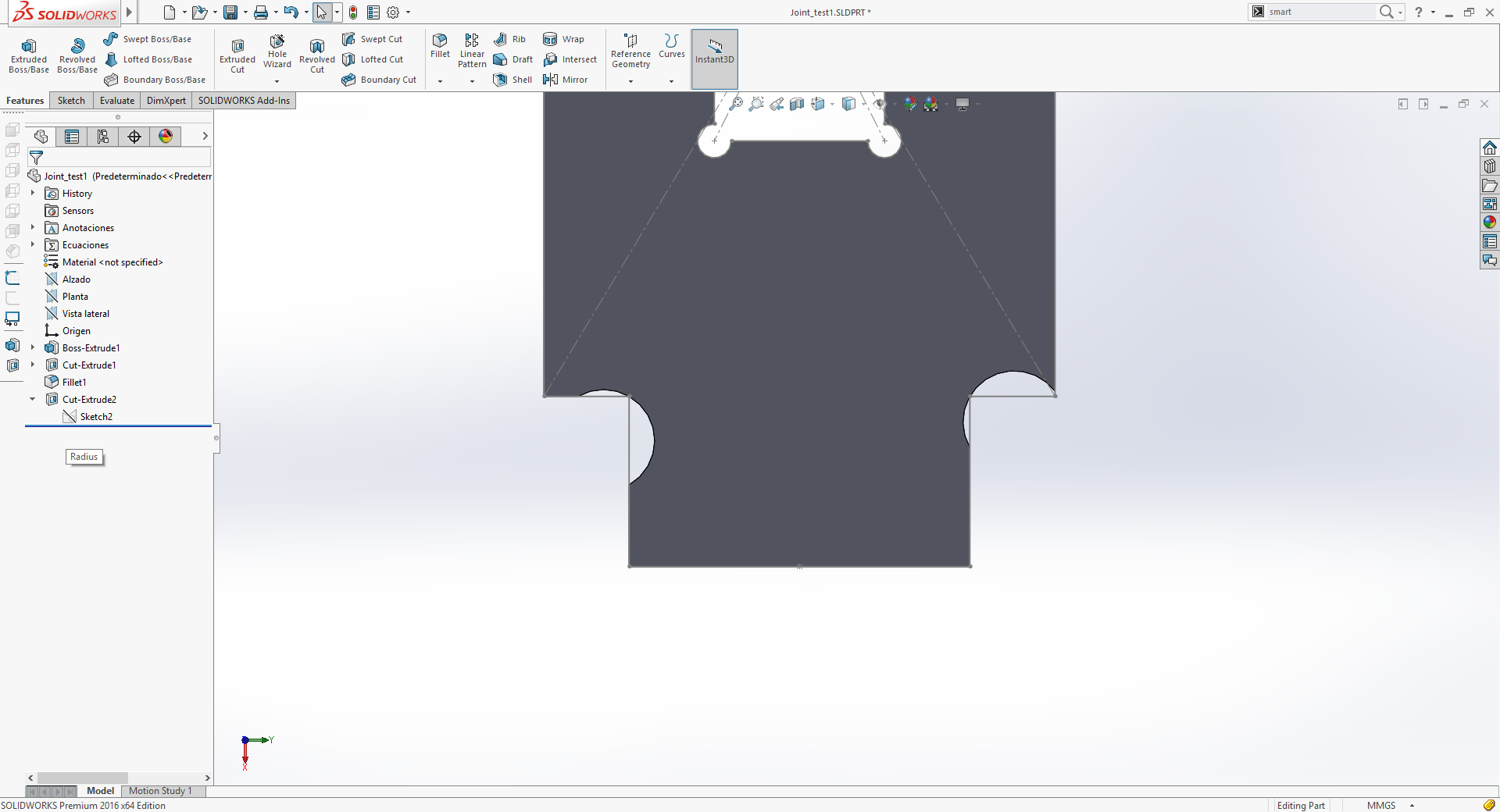
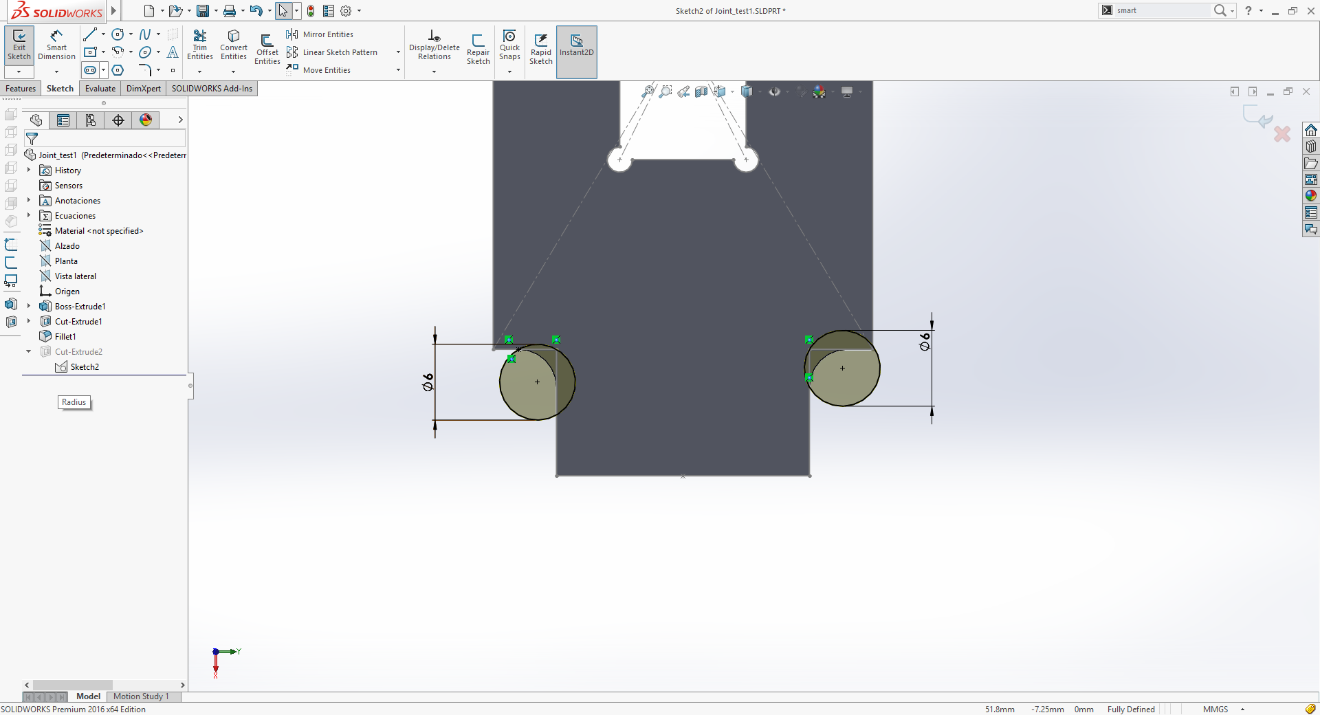
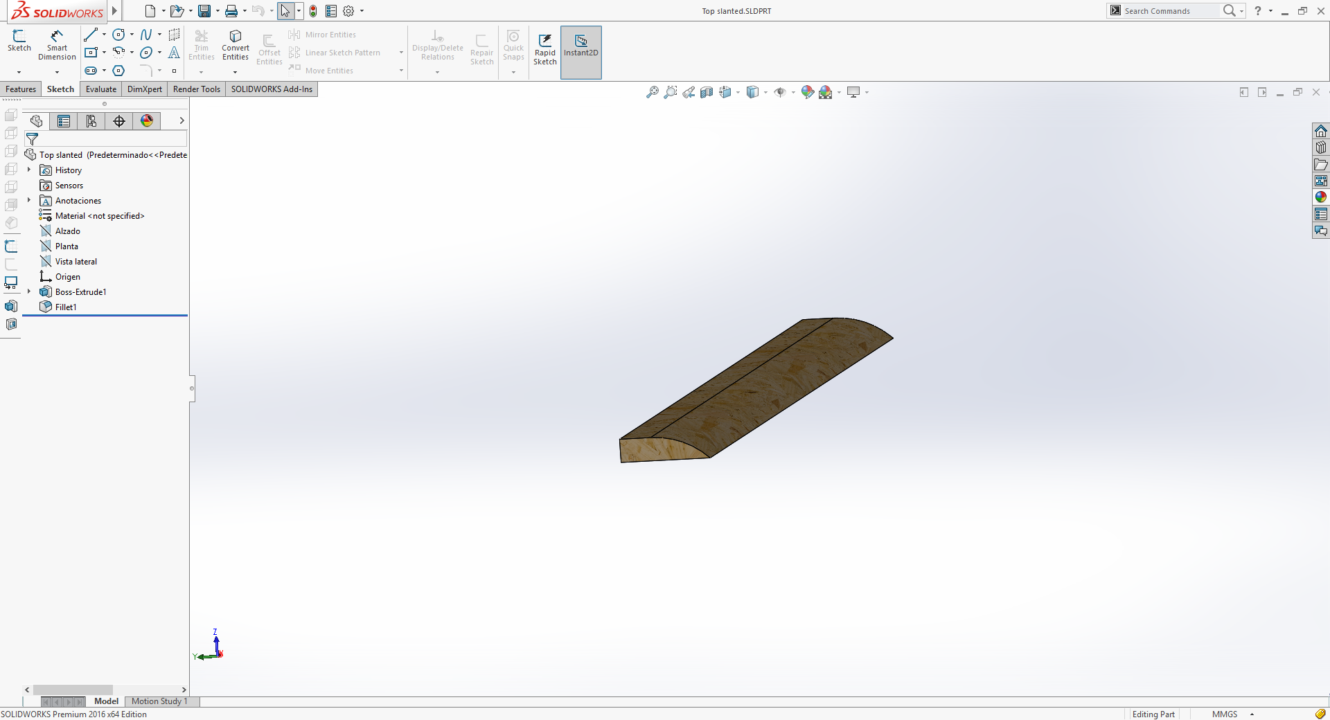
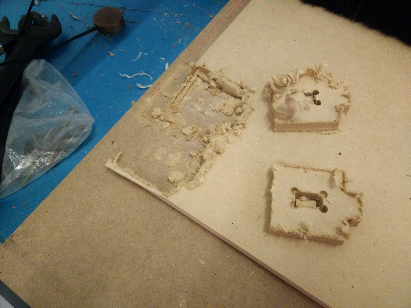
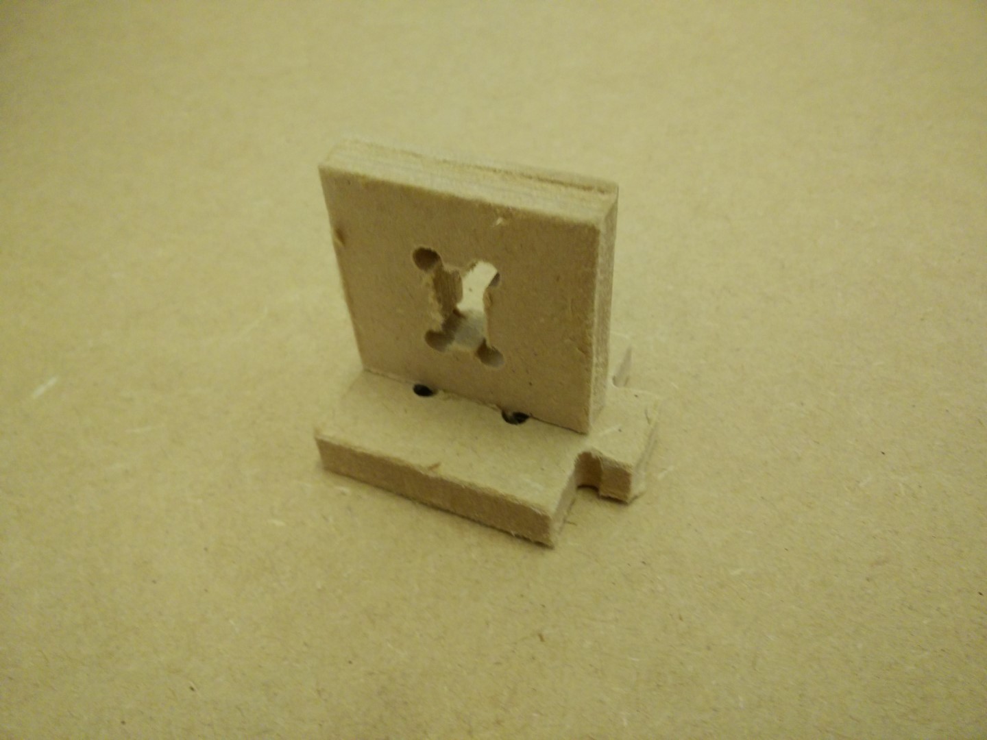
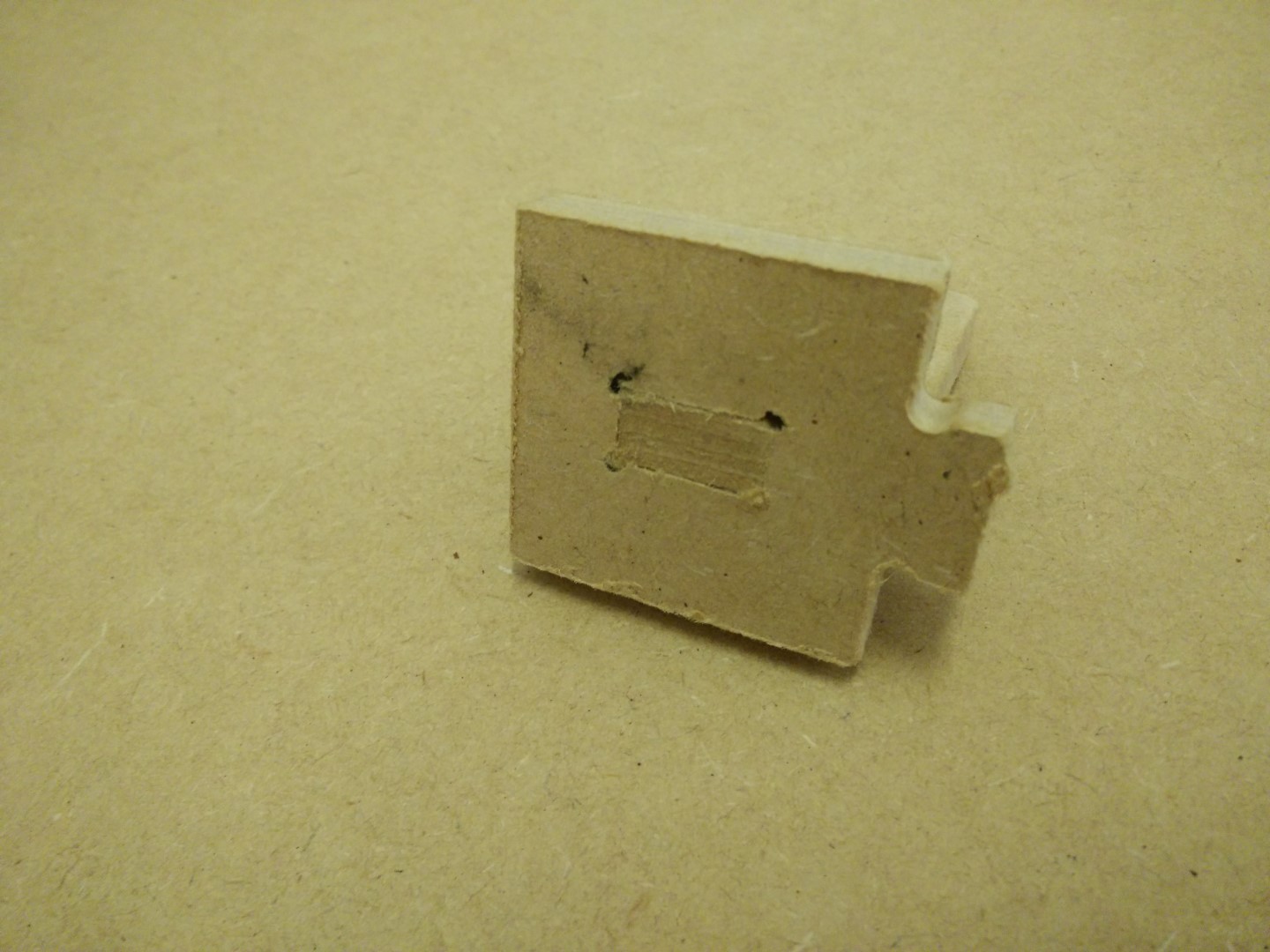
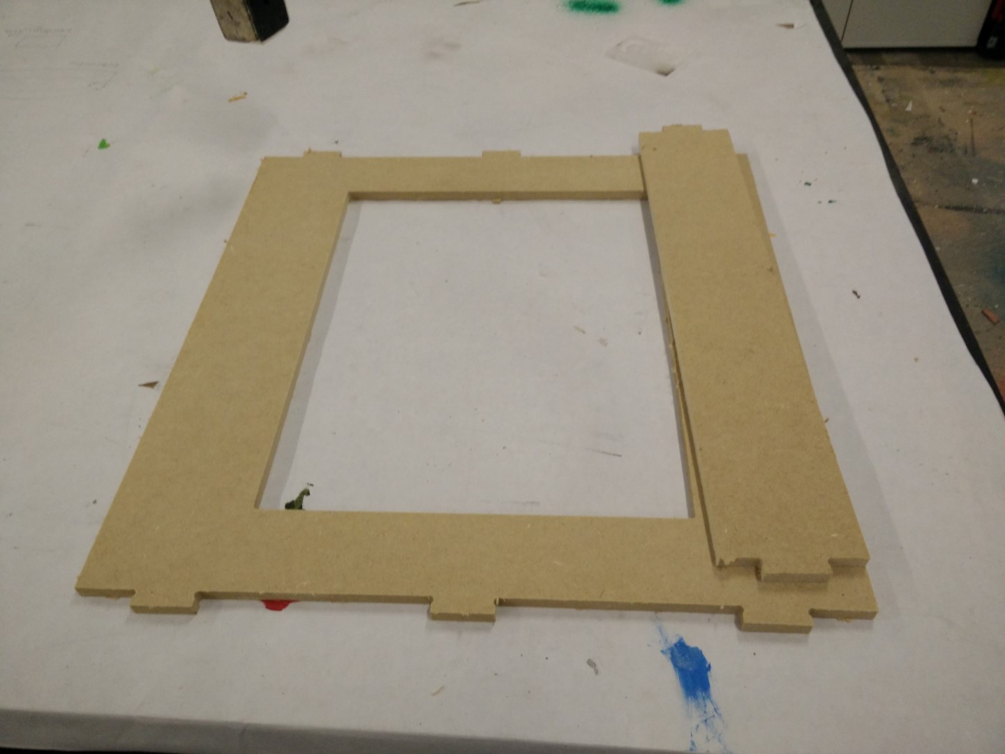
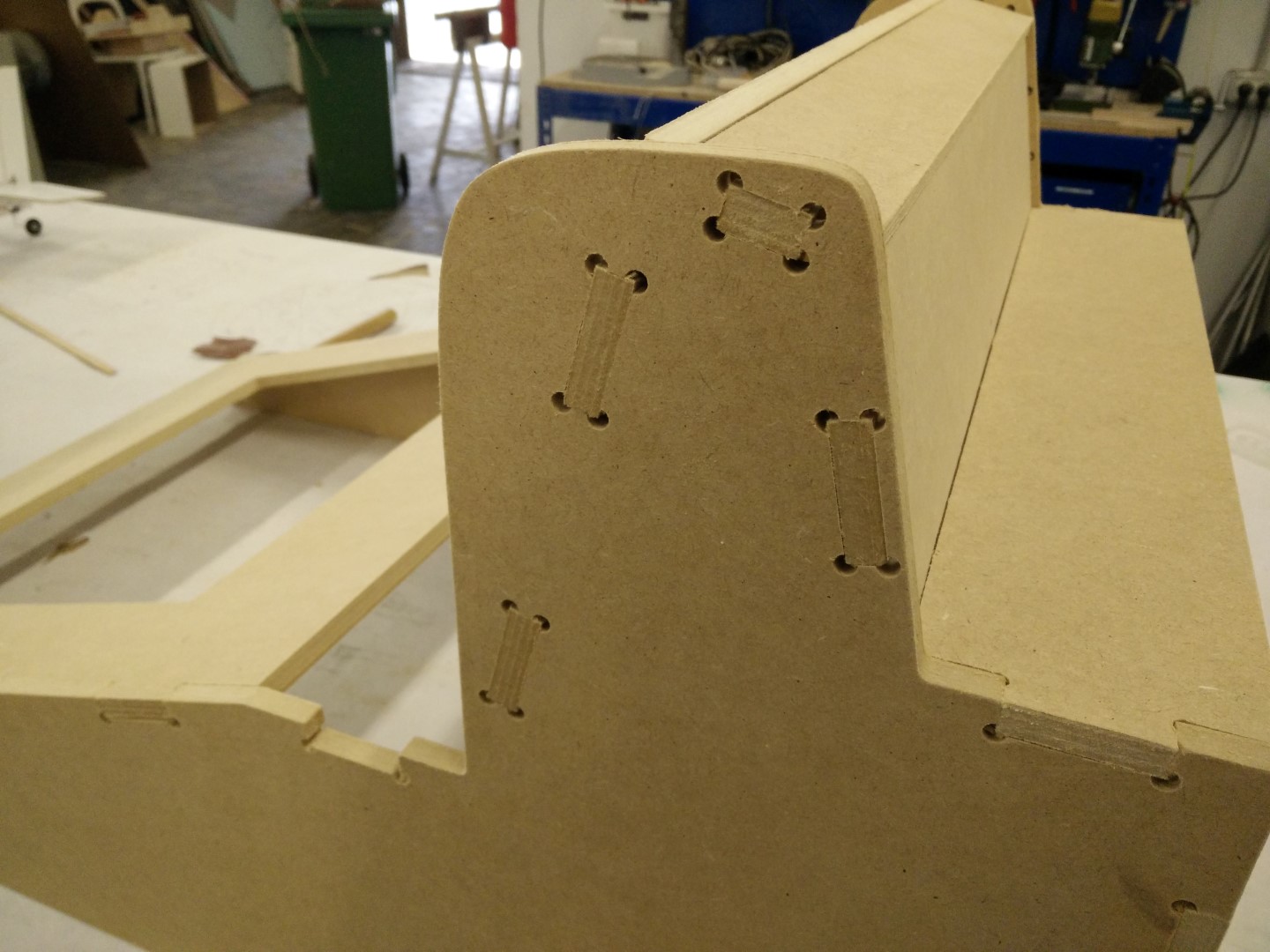
Then I realized that I needed to check press fitting and decided to do a test part to mill and check for tolerances and joint design. One of disadvantages of the CNC is the inhability to inside contours with sharp edges, as the tool is cilyndrical and will always leave a round edge with the radius of the tool. So if you need to clear an square inside area, you need to do some extra milling on the corners.
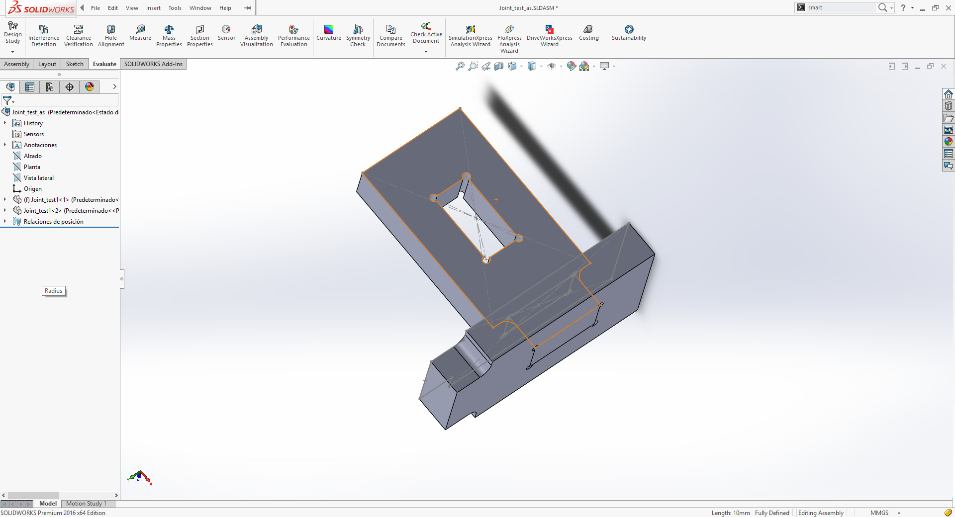
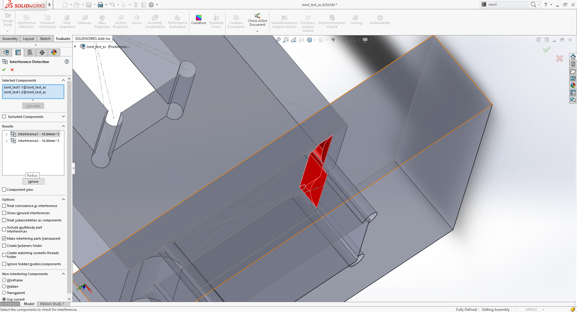
I realy liked to run the interference check, I knew it could be done but never tried before. It was quite usefull to check for misalignments and wrong measures during main assembly.
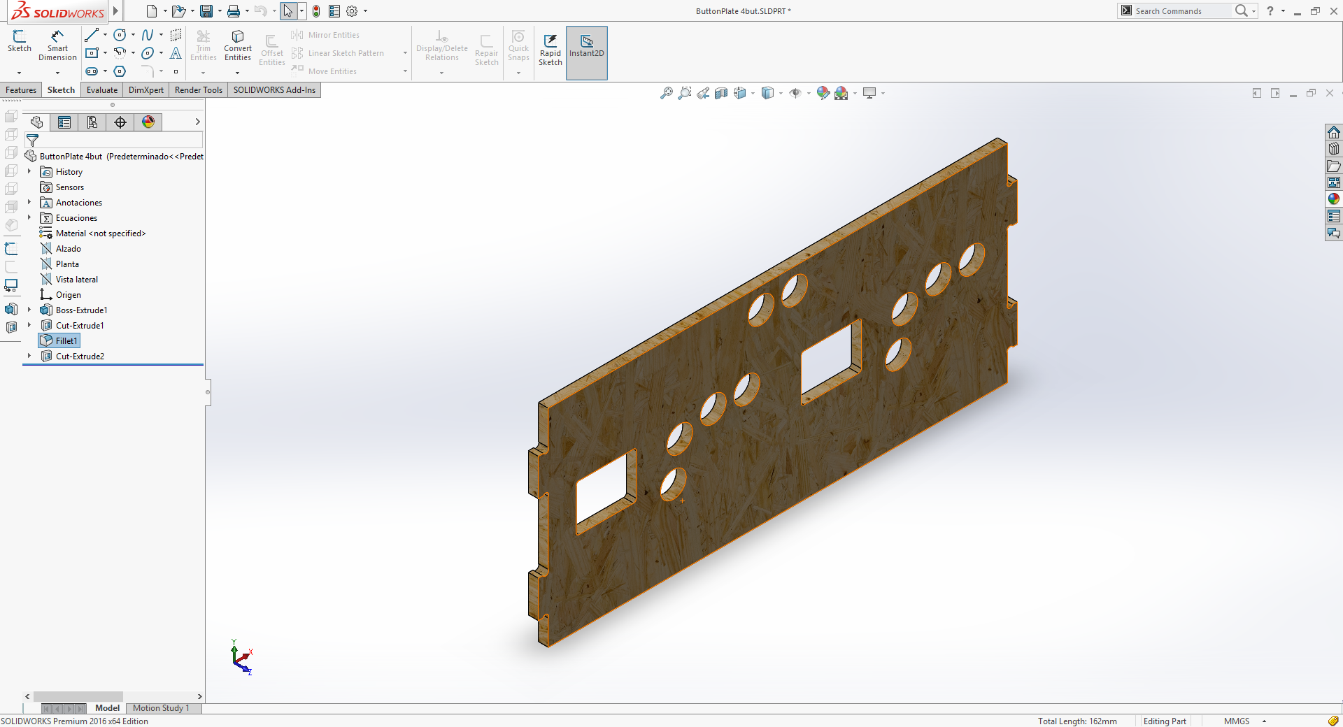
By writing comments on the pictures that I've probably choosen the hole to clear the edge wrong, as the one on the right on the last photograph on the carousel above leaves more surface to contact the connecting part, maybe creating a strongest assembly. Nevertheles, after making it, it's strong enough.
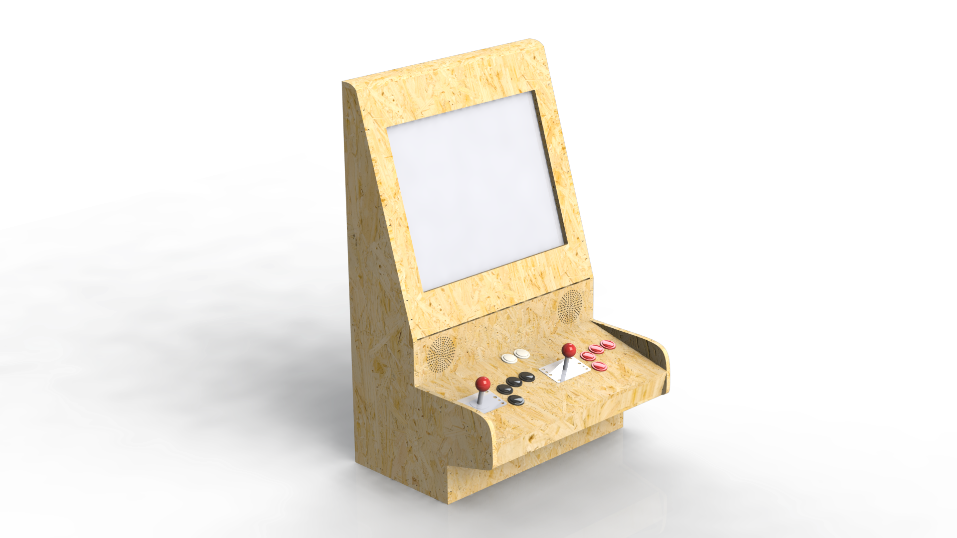
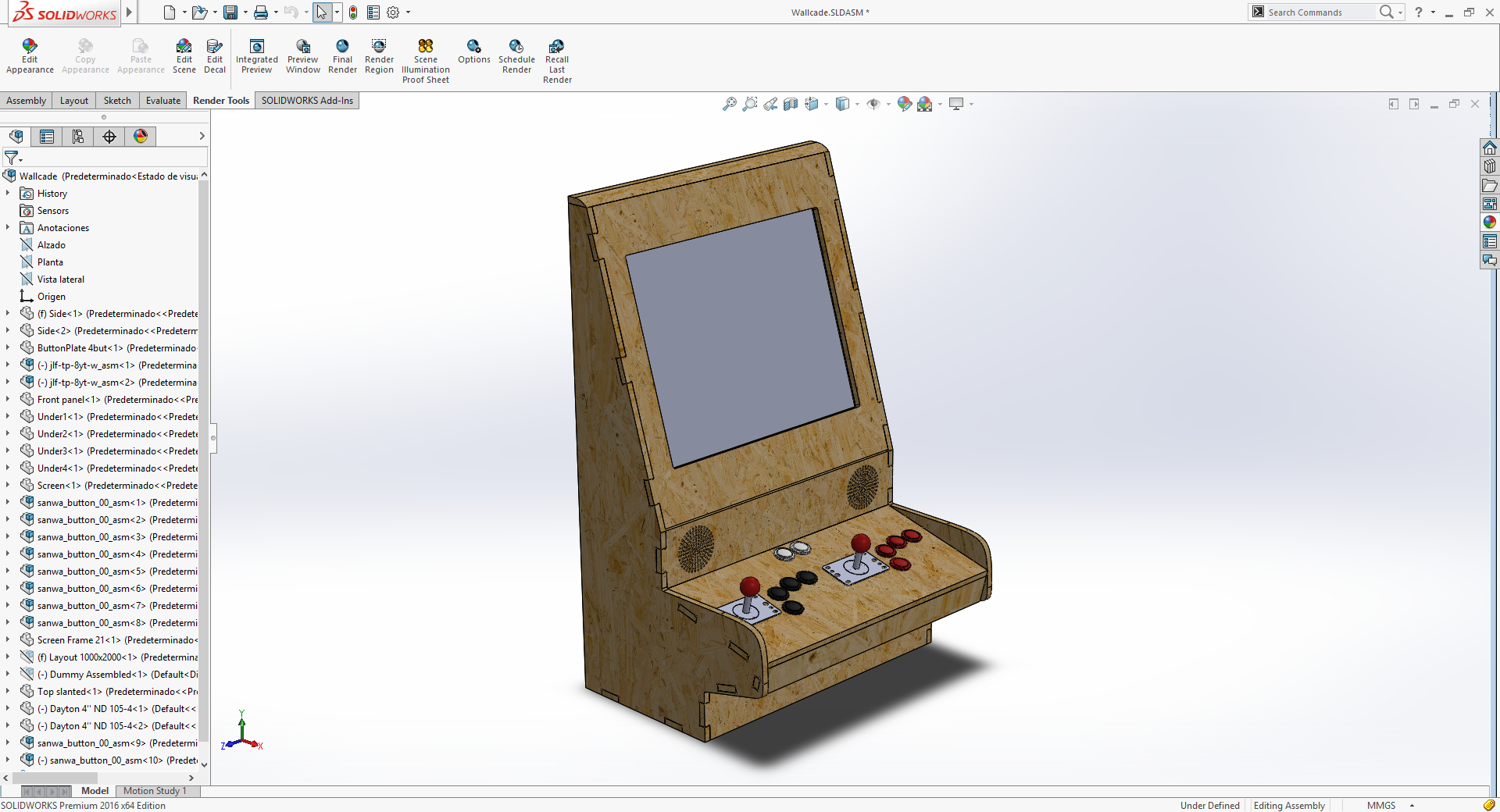
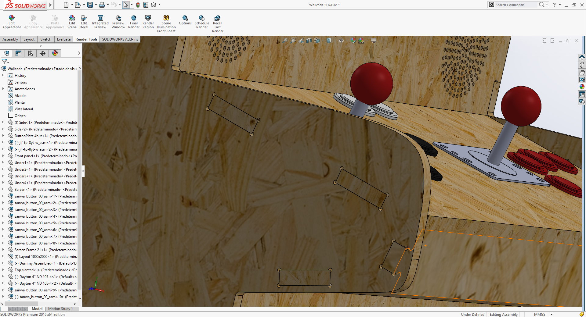

For this assembly I've also used some models from grabcad.com like the joysticks, the speakers and the buttons. I've also grabbed a dummy that was the only thing available (at grabcad) to simulate a human pose with the cabinet.
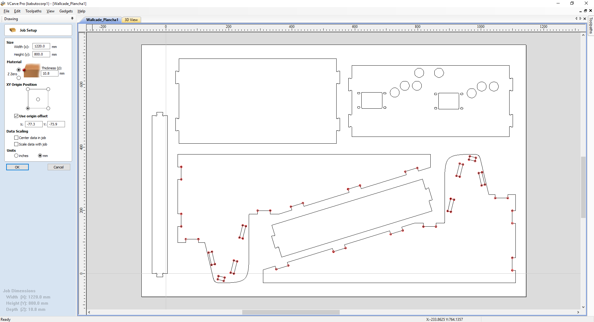
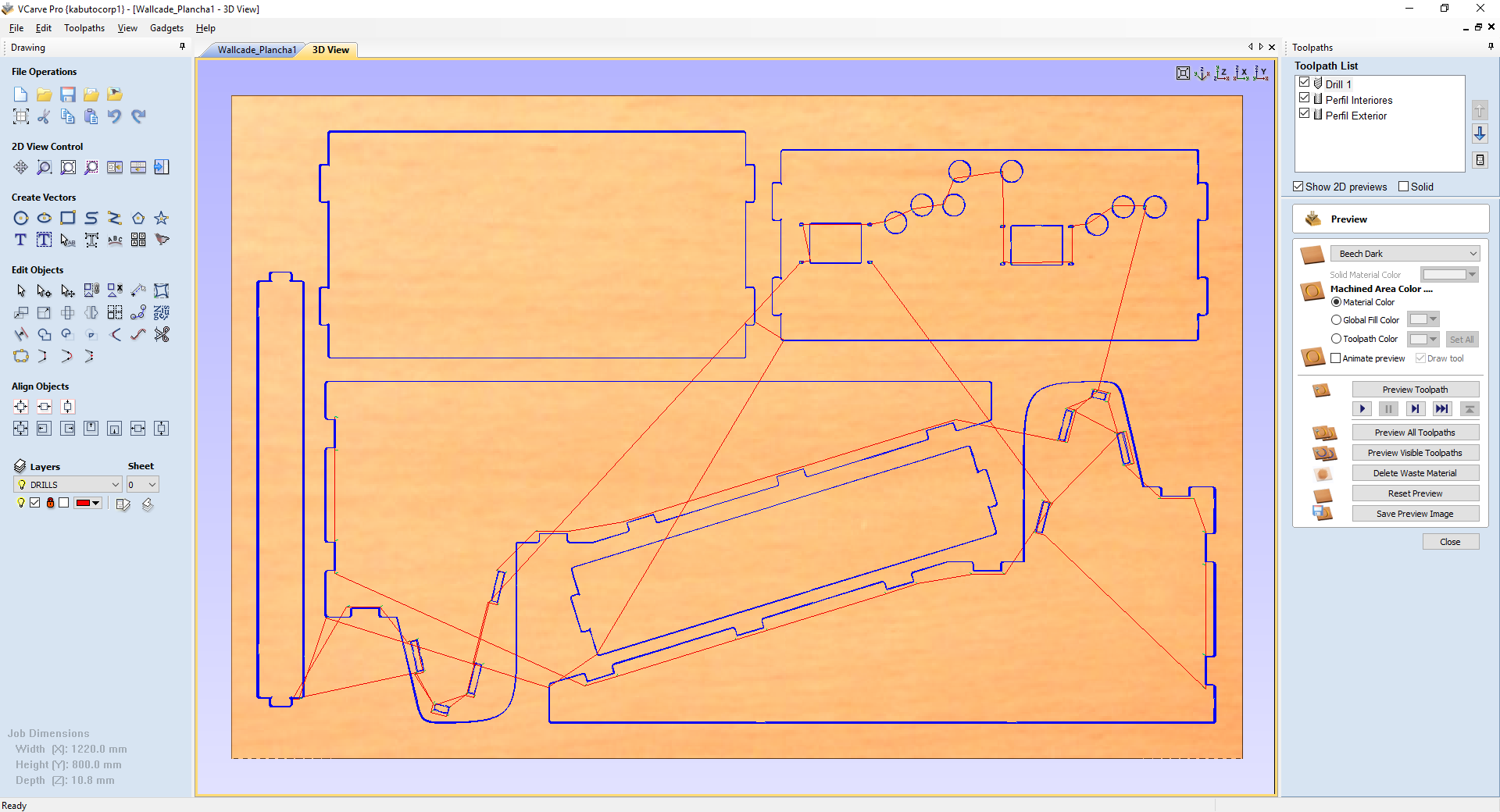
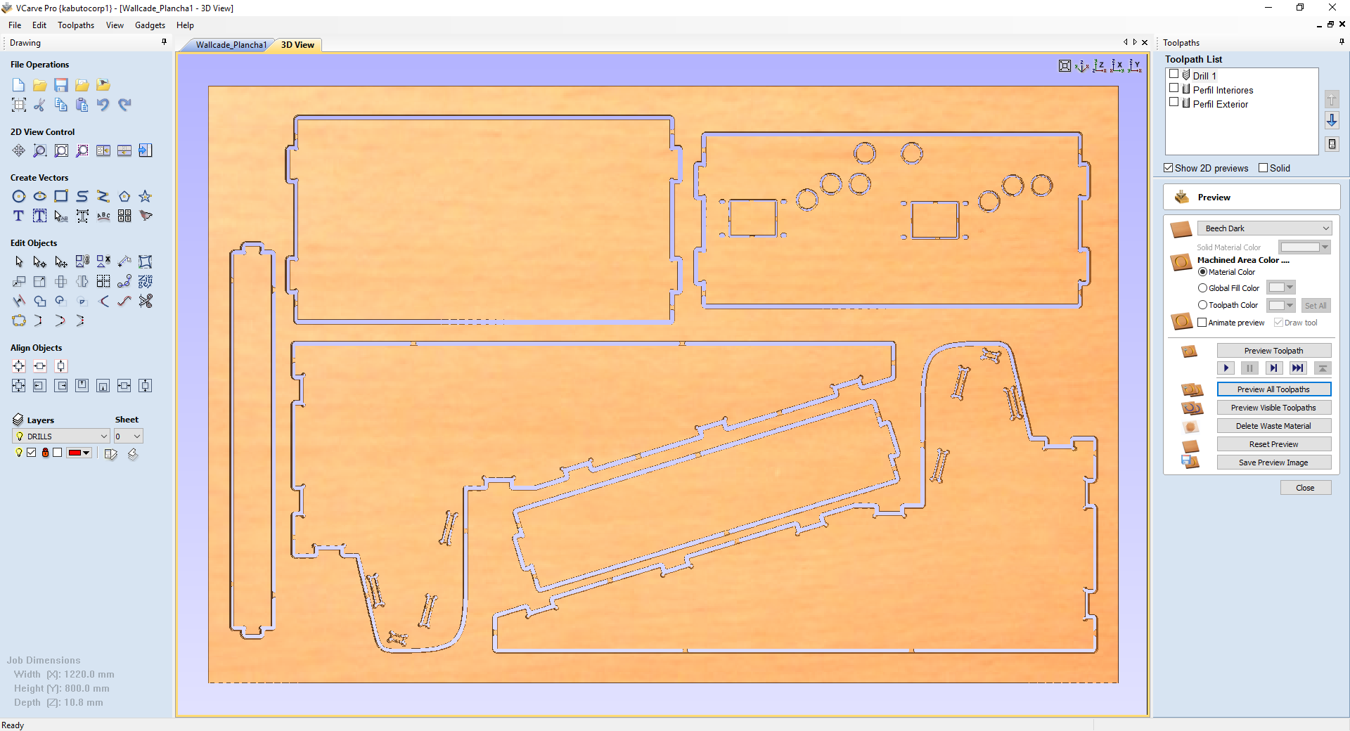
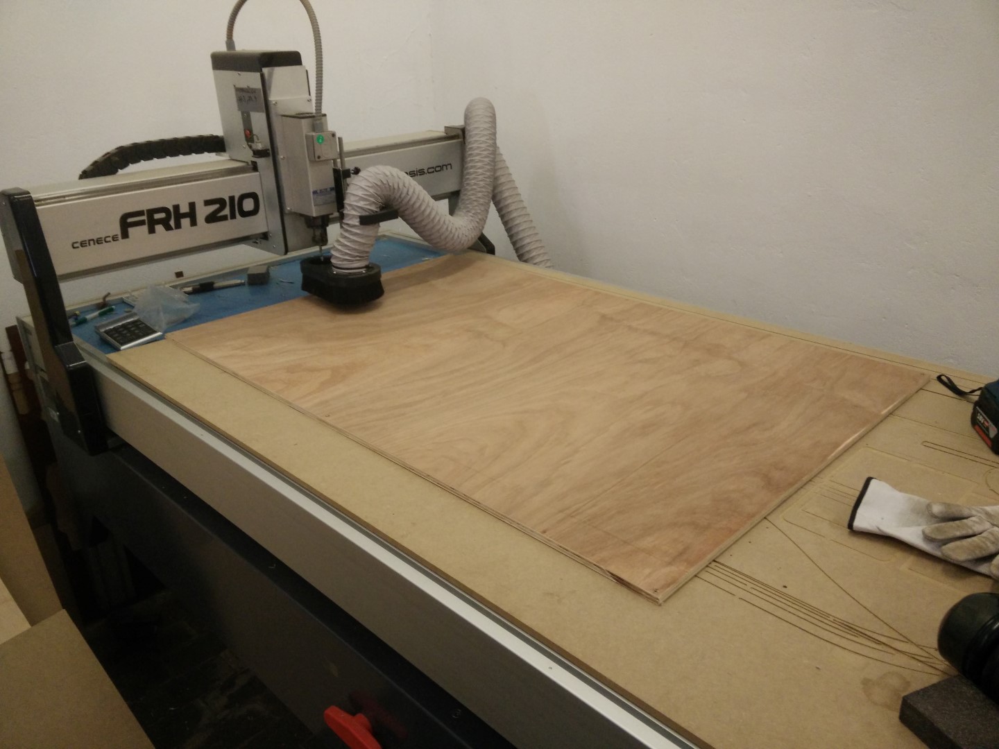
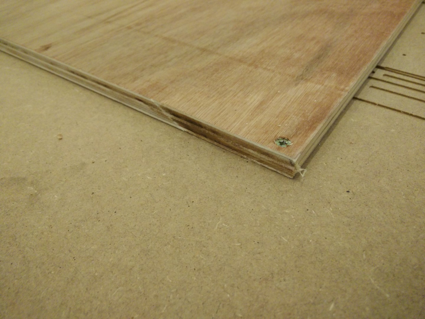
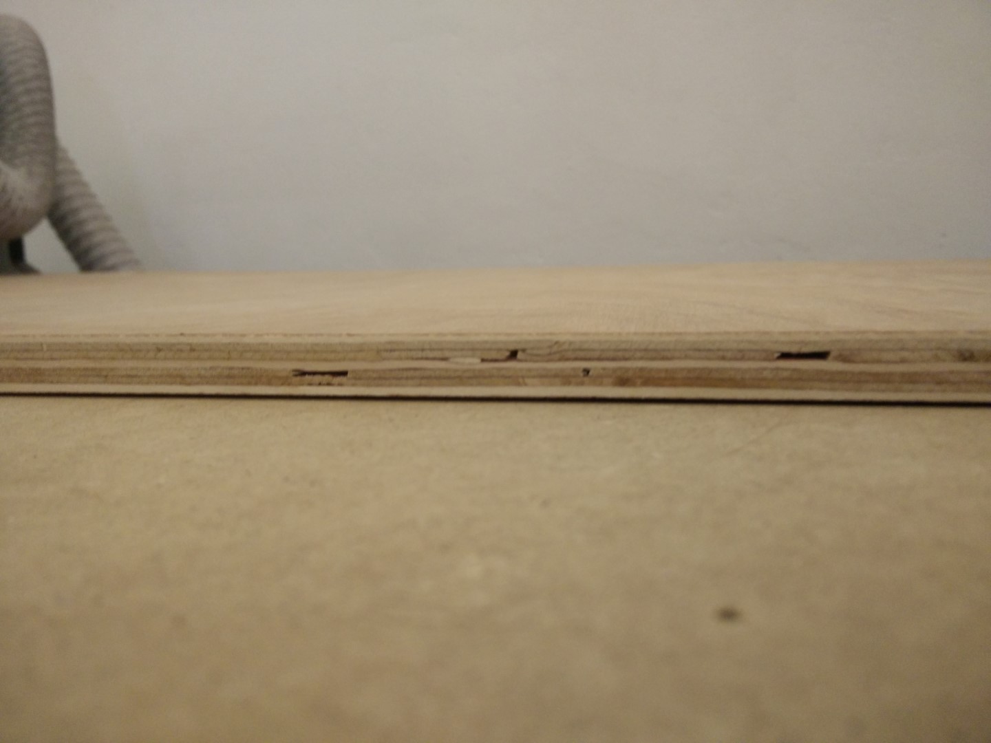
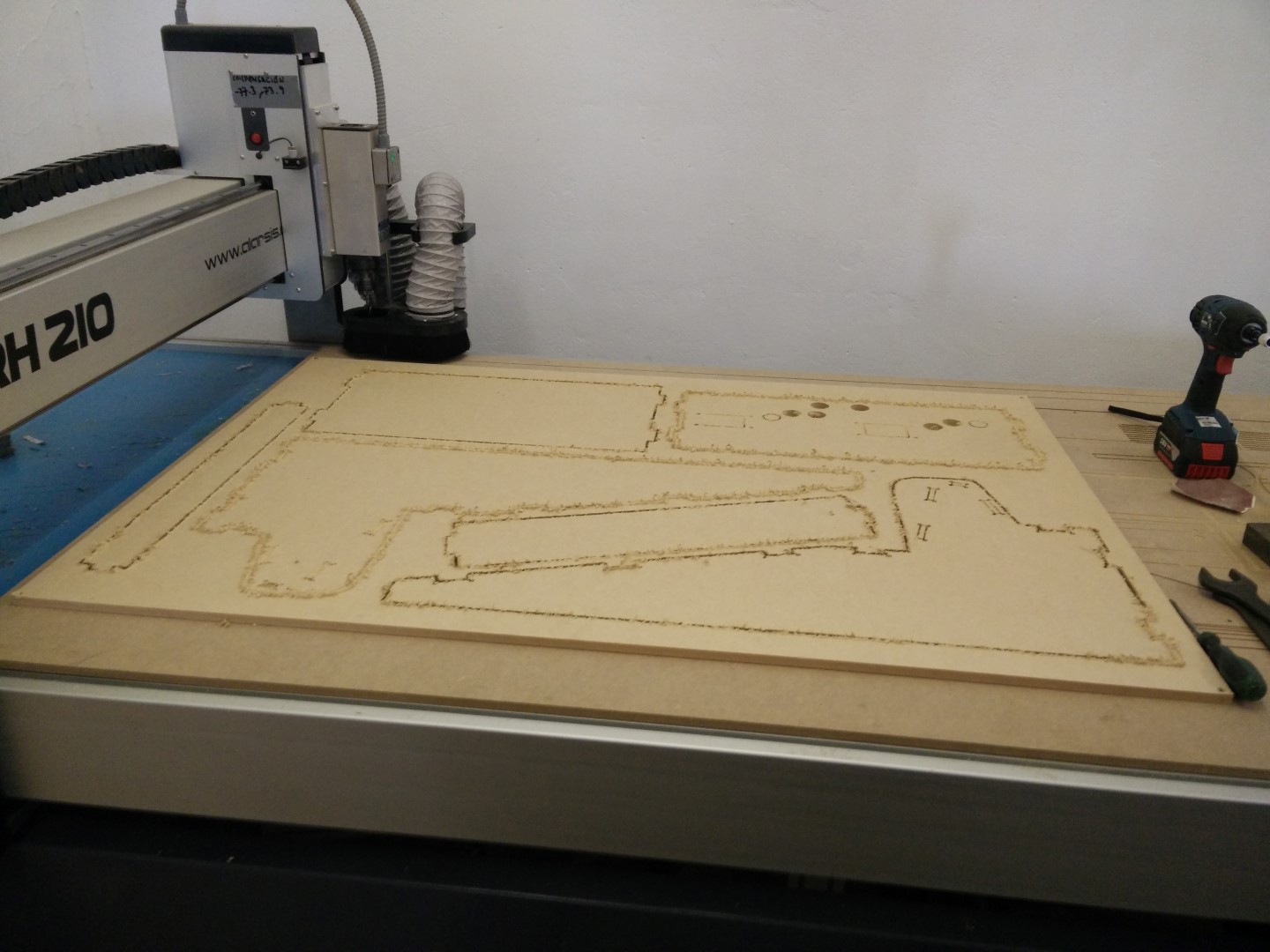
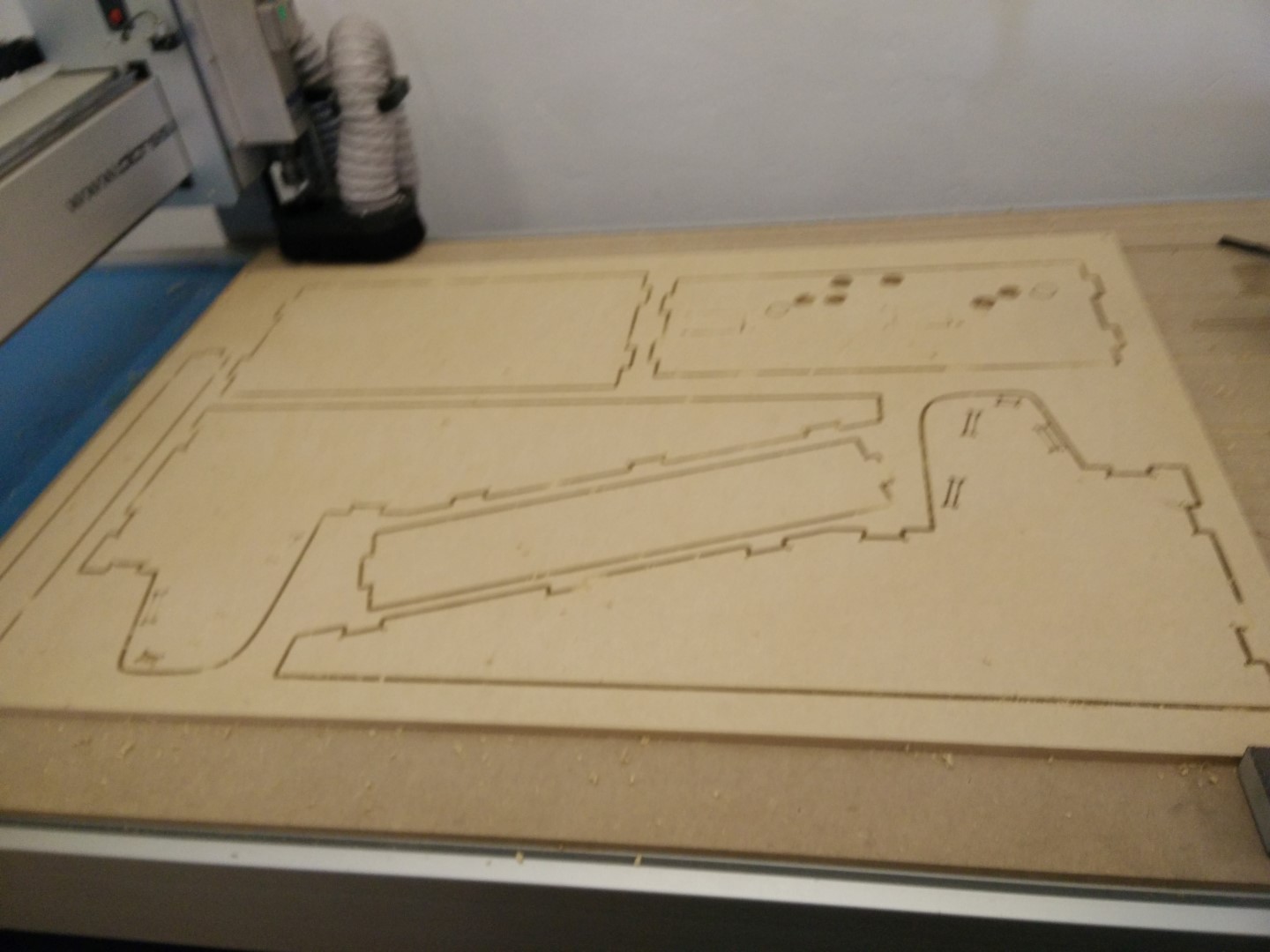
I had a couple of 1000x800mm plywood sheets and several 1000x800 MDF sheets, both "10mm" thick. So as plywood looks better than MDF I started the first joint tests on plywood. I'm using an MDF sacrifice board and screwing corners onto it, because the board is a bit curved.
I've ordered some parts from aliexpress, a couple of joysticks and some buttons as well as a couple of boards that emulate usb joystick controllers. But all of those could be made at the Fab Lab, in fact David designed a board using an ATmega32u4 that emulates USB and he gave it to me so I can also test it and think of possible improvements.
Source files:
vCarve Files
SolidWorks Files