Assignments
This week I had a problem following the assignment but I'm considering it uncomplete. This is because I didn't get the 1/64" mill bit in time. On the other hand I consider my soldering assignment complete since I've soldered quite a few times, including SMD, cables and connectors, boards... I'm not such proficient with the air gun, but getting better every time.
But I didn't really lacked mill bits, I had access to some, a v-bit of unknown angle, a couple of 0.7mm and a 2.0 mm routing bits. And the MDX-40 isn't really used at the fablab because we use the big one (2000x1000mm) for everything we mill and we allways use acid for making PCBs.
Most of the process is explained in the pictures, even when I didn't come with an ISP, I've learned a lot this week and I'll definitely use the MDX this year for PCBs and with the artists in residency at the fabLAB.
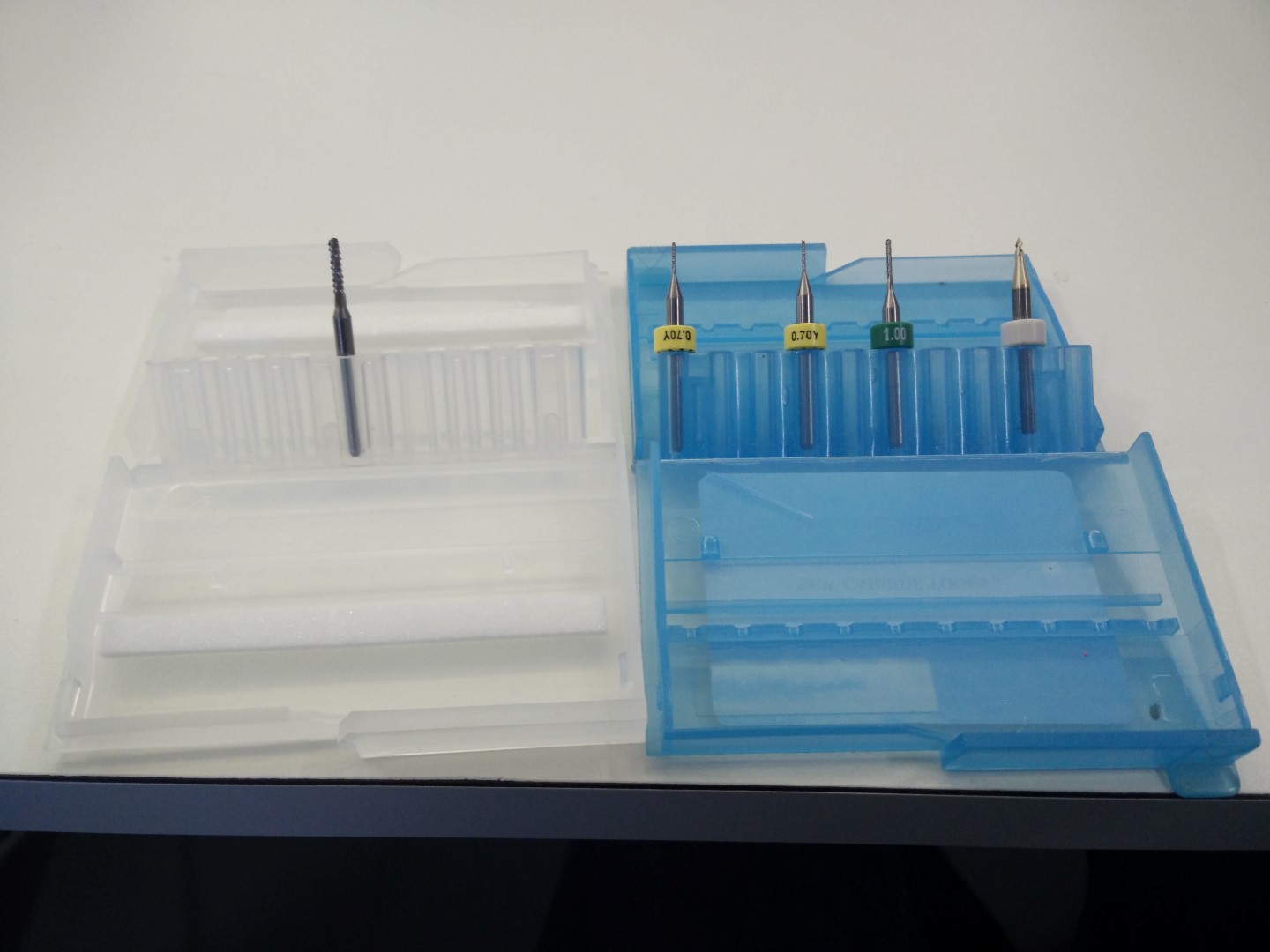
Mills available by now
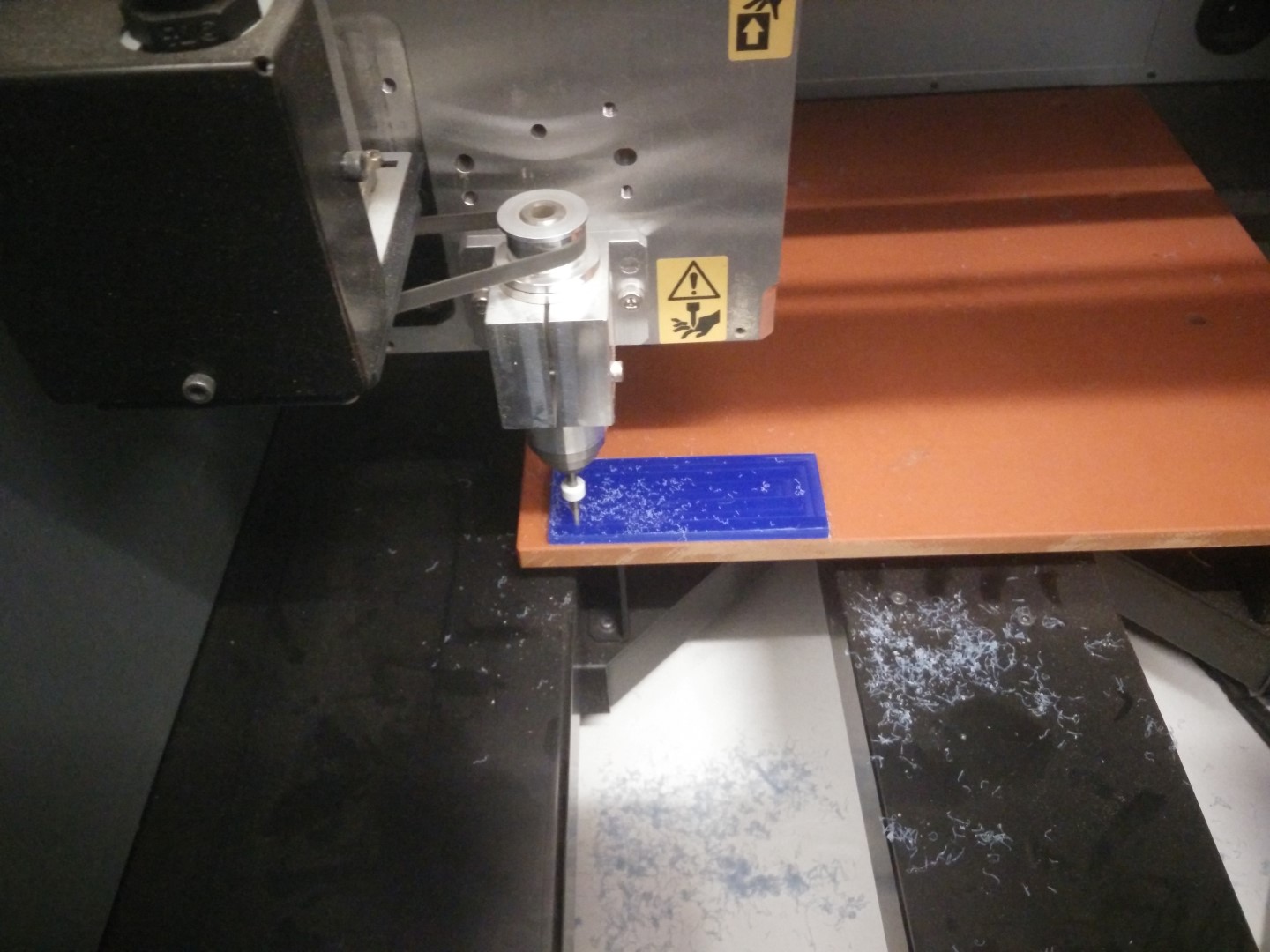
First testing with wax
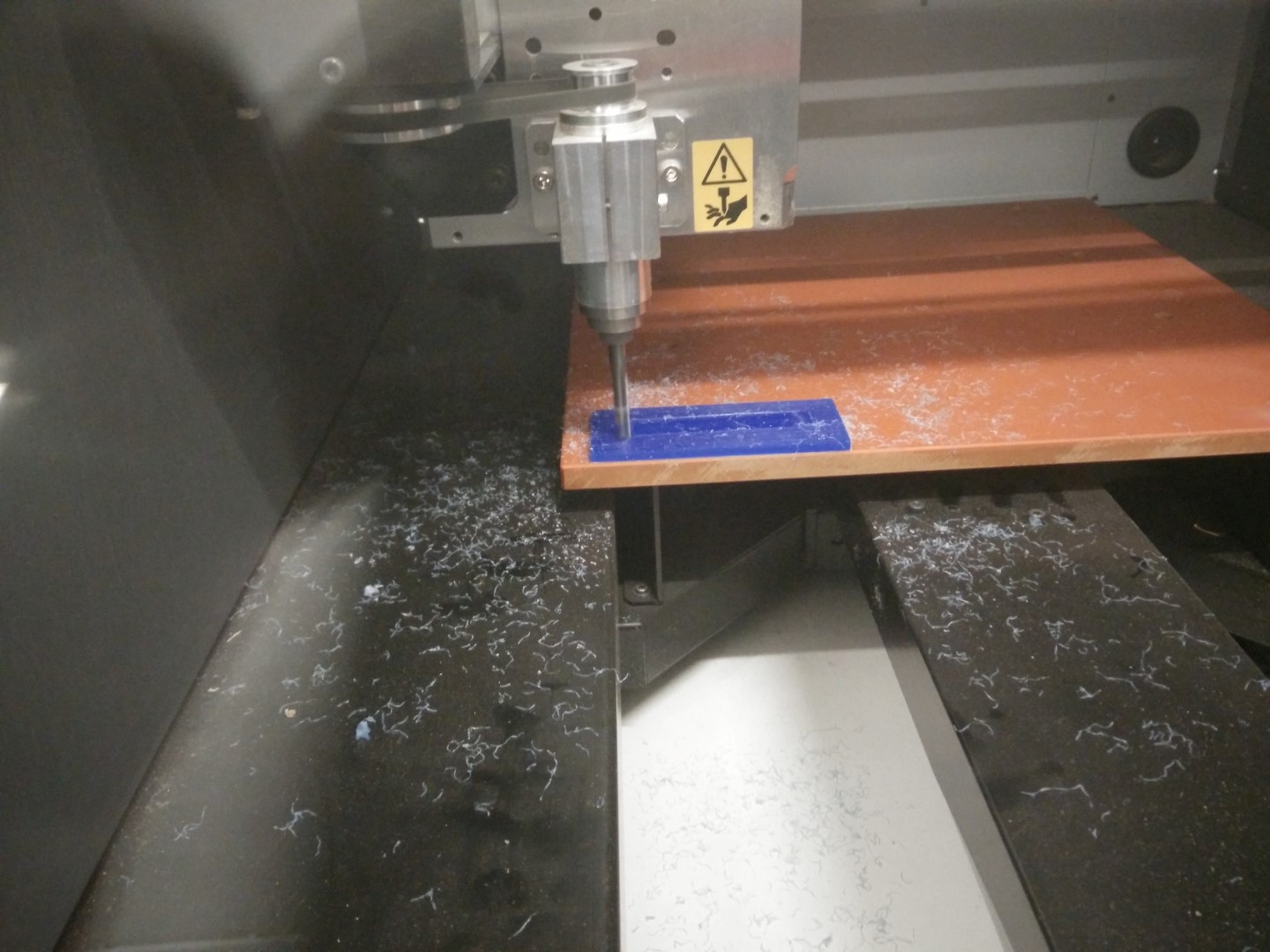
Make it flat, beautiful shades of the milling process.
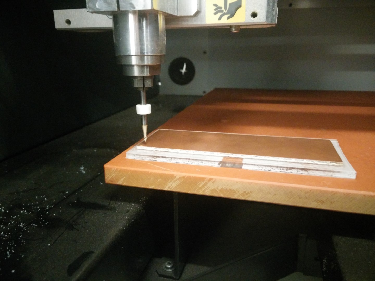
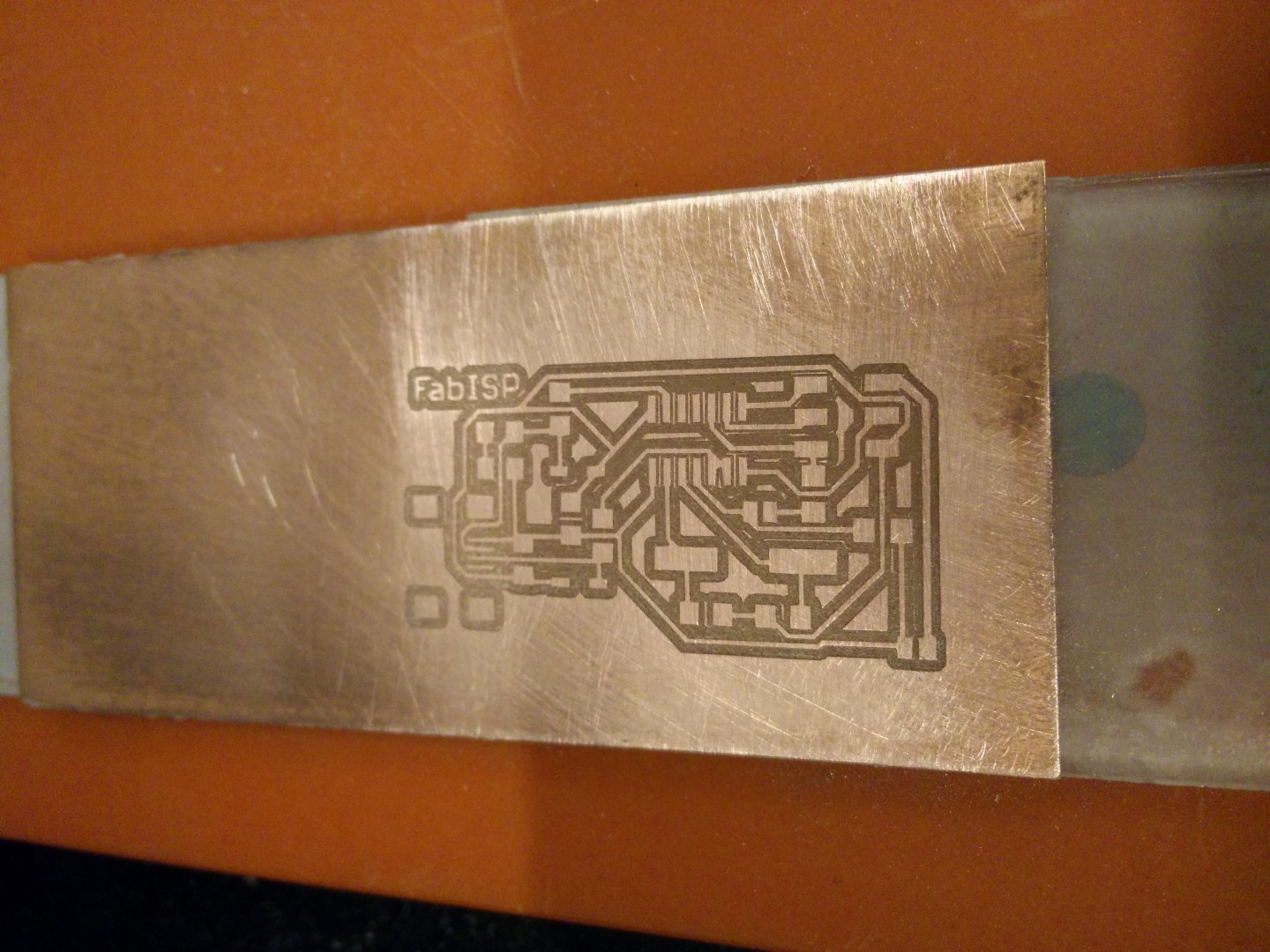
Testing the V bit with PCB traces 1/64" process 0.1mm depth
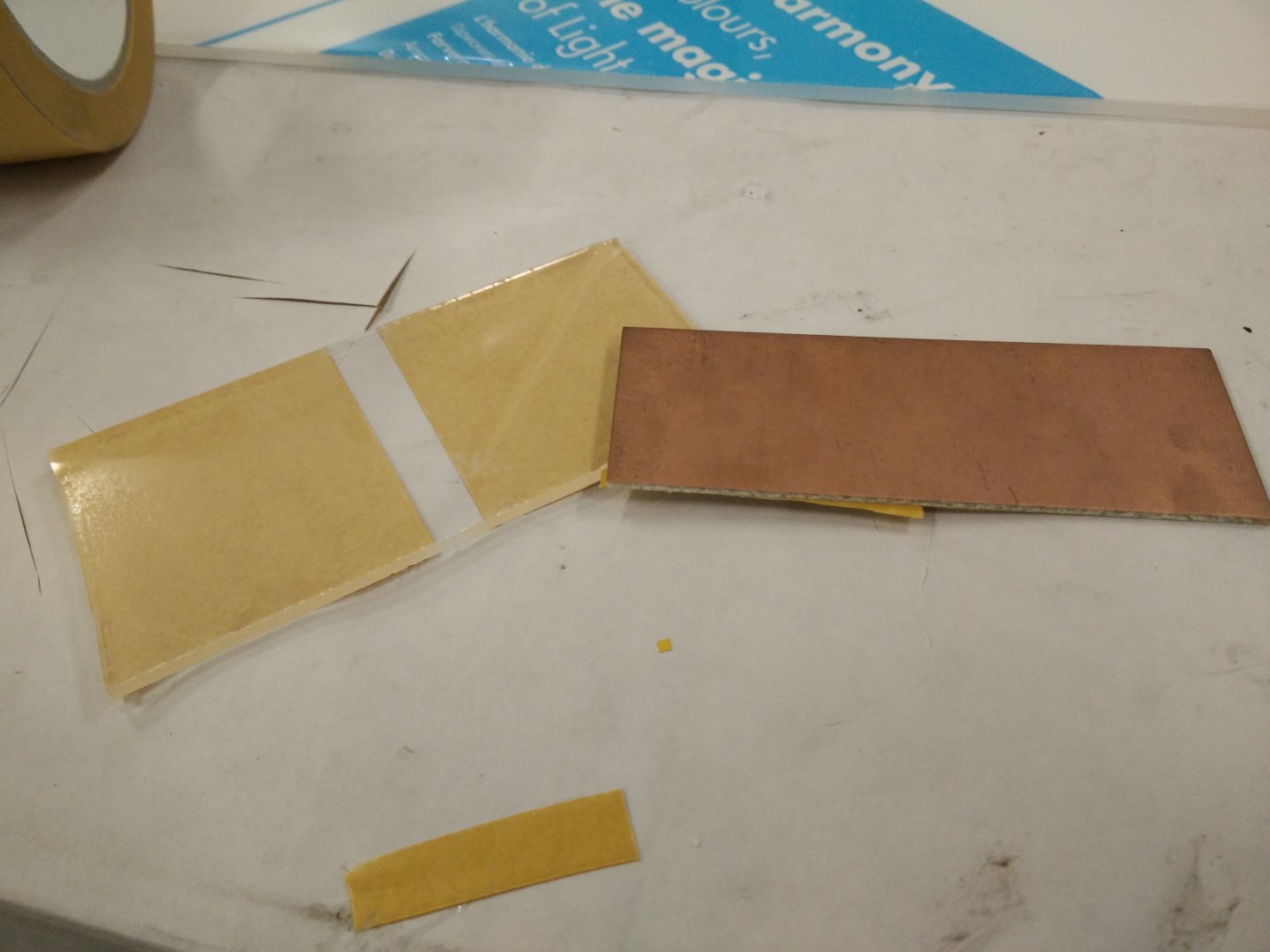
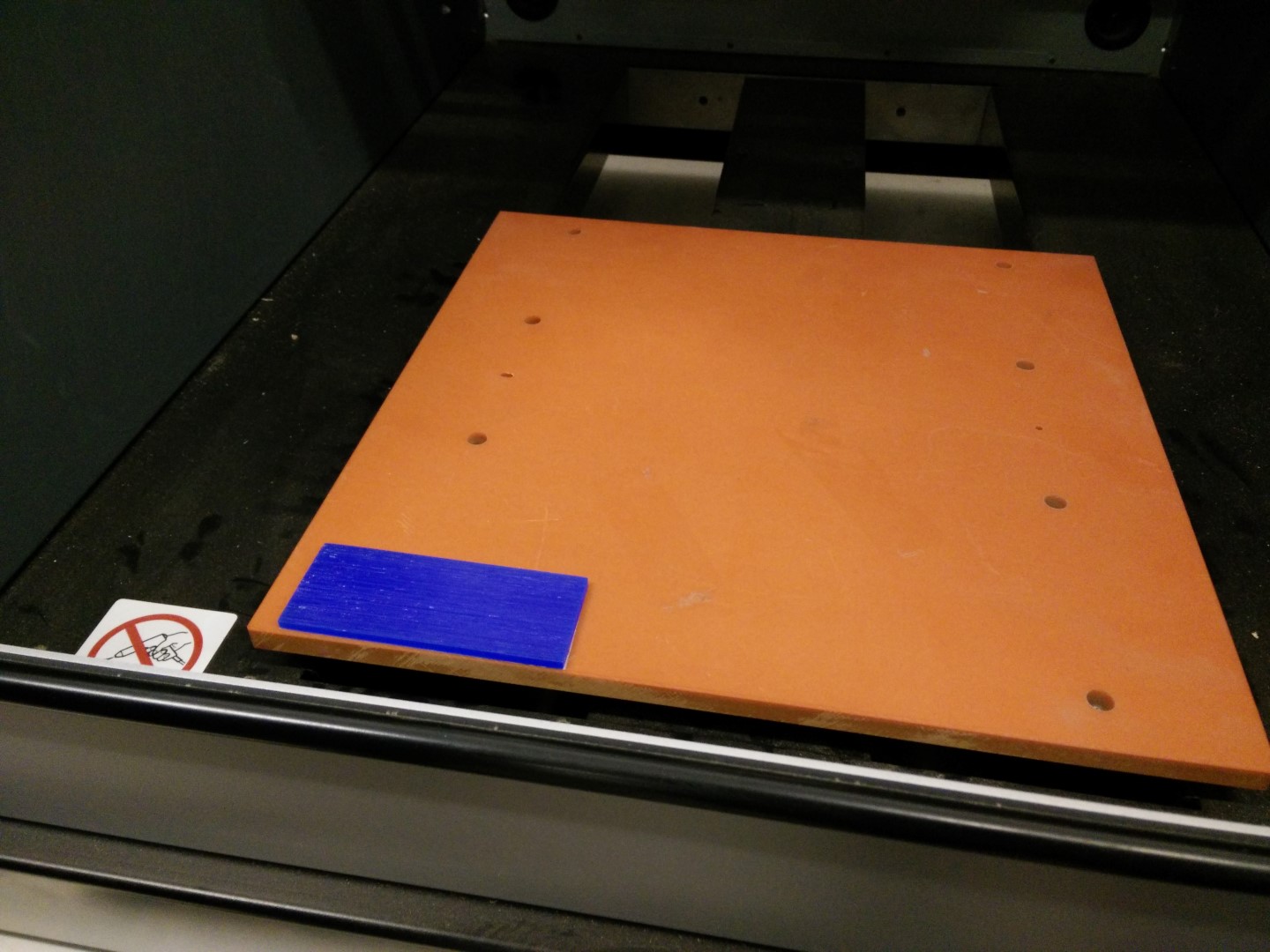
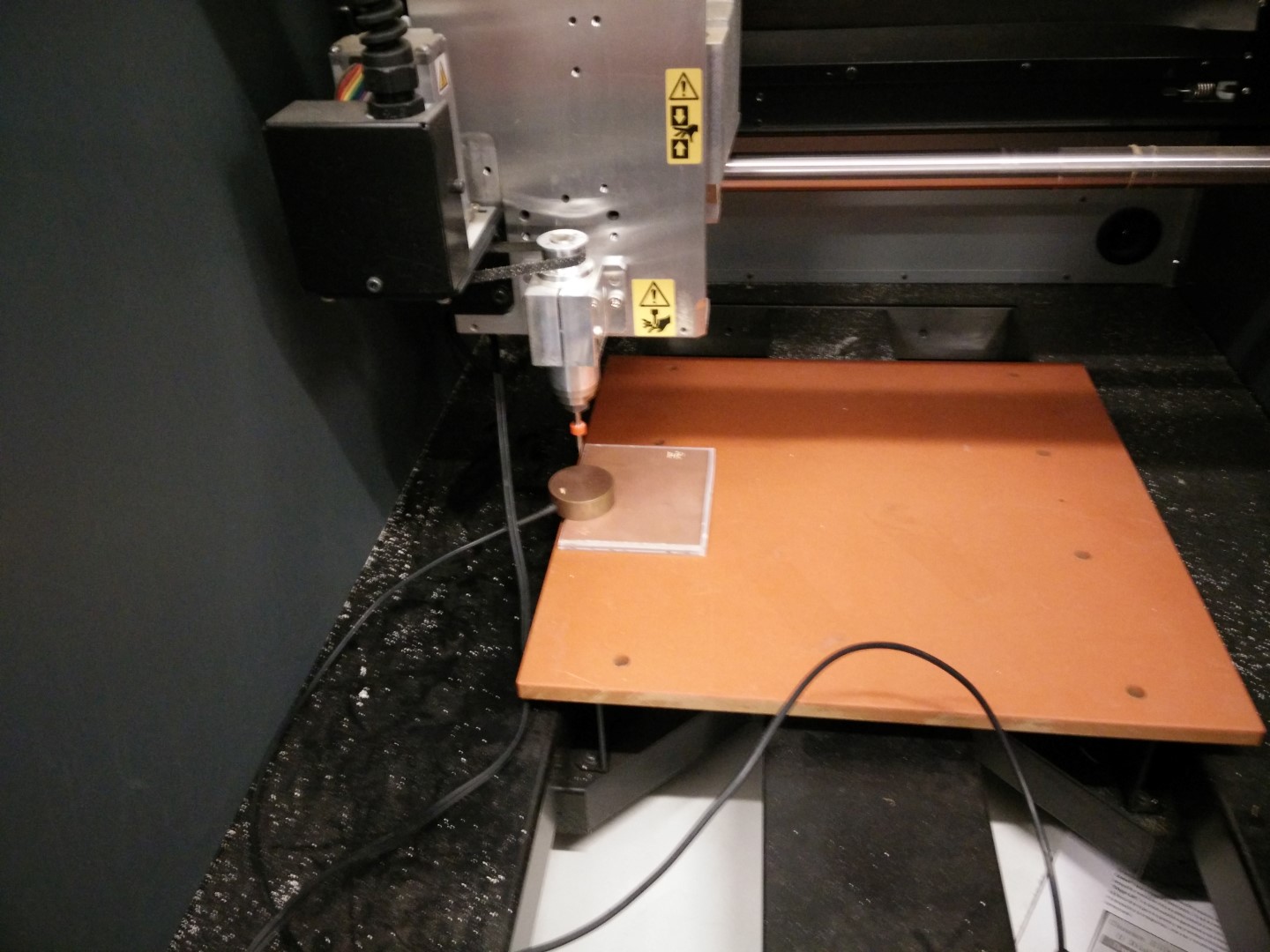
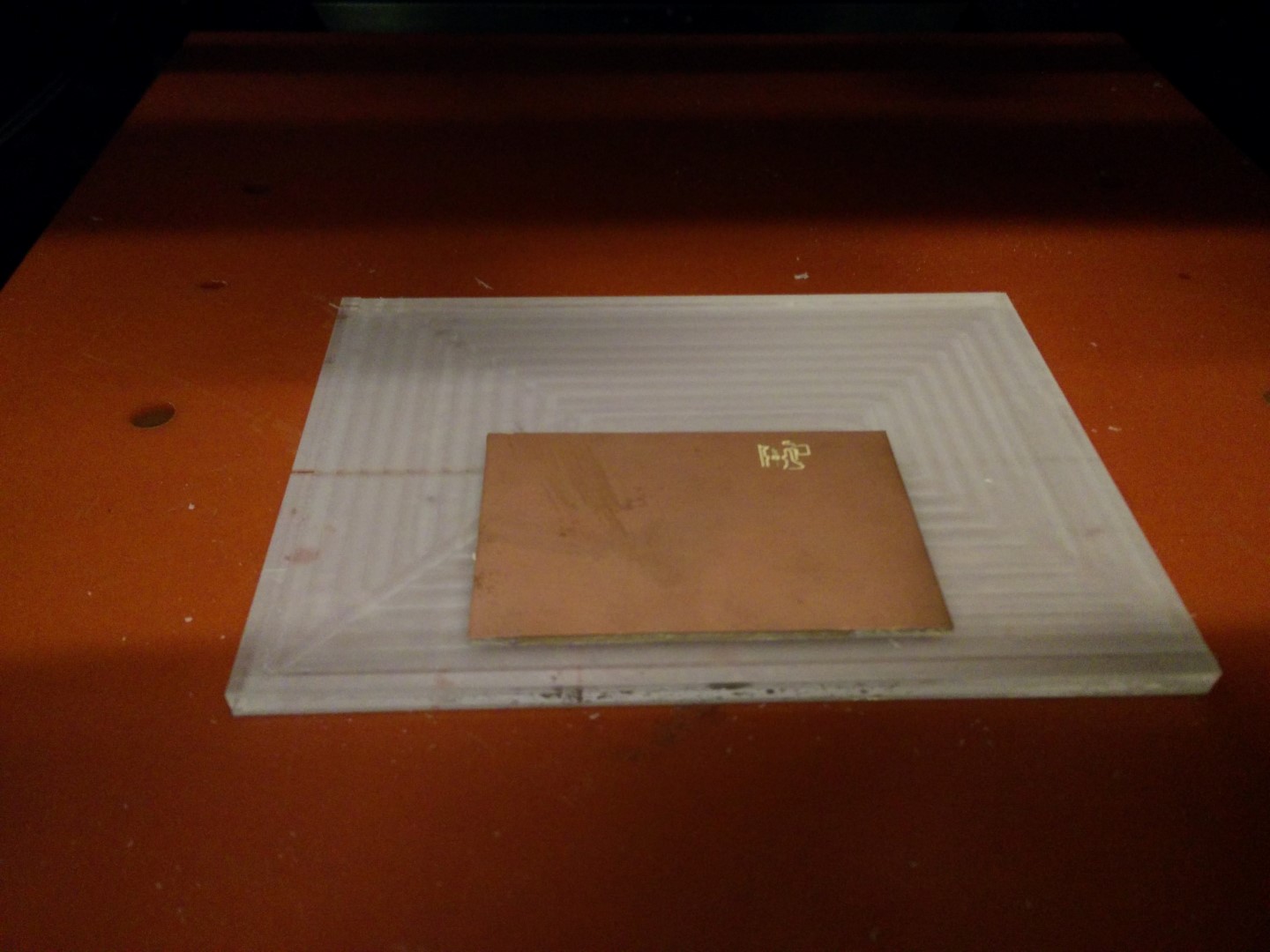
A piece of plexy and a piece of FR1 for testing
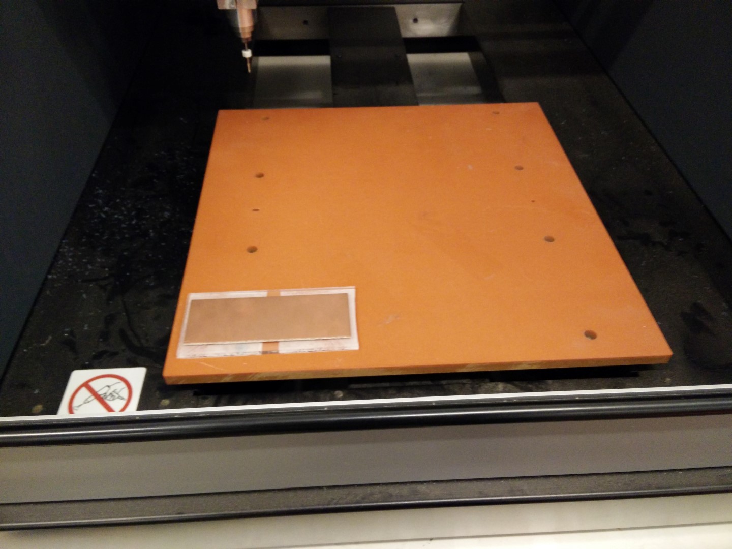
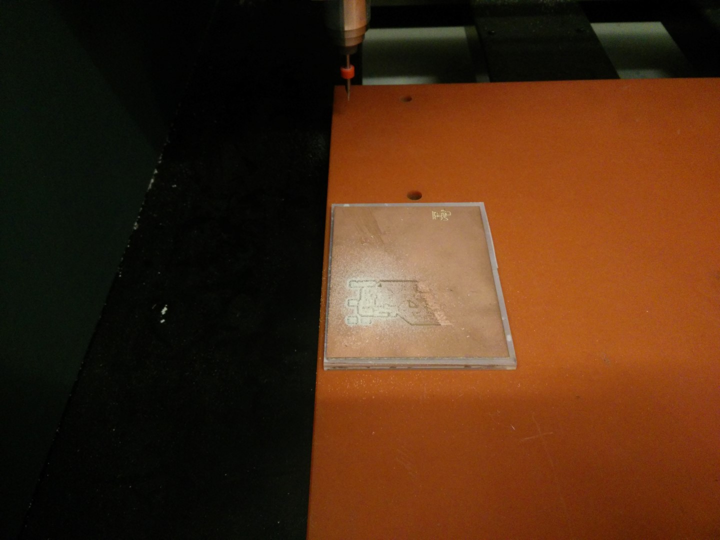
Placement on the MDX40
First result, flatness is critic.
With a V bit the deeper you go, the thicker you get
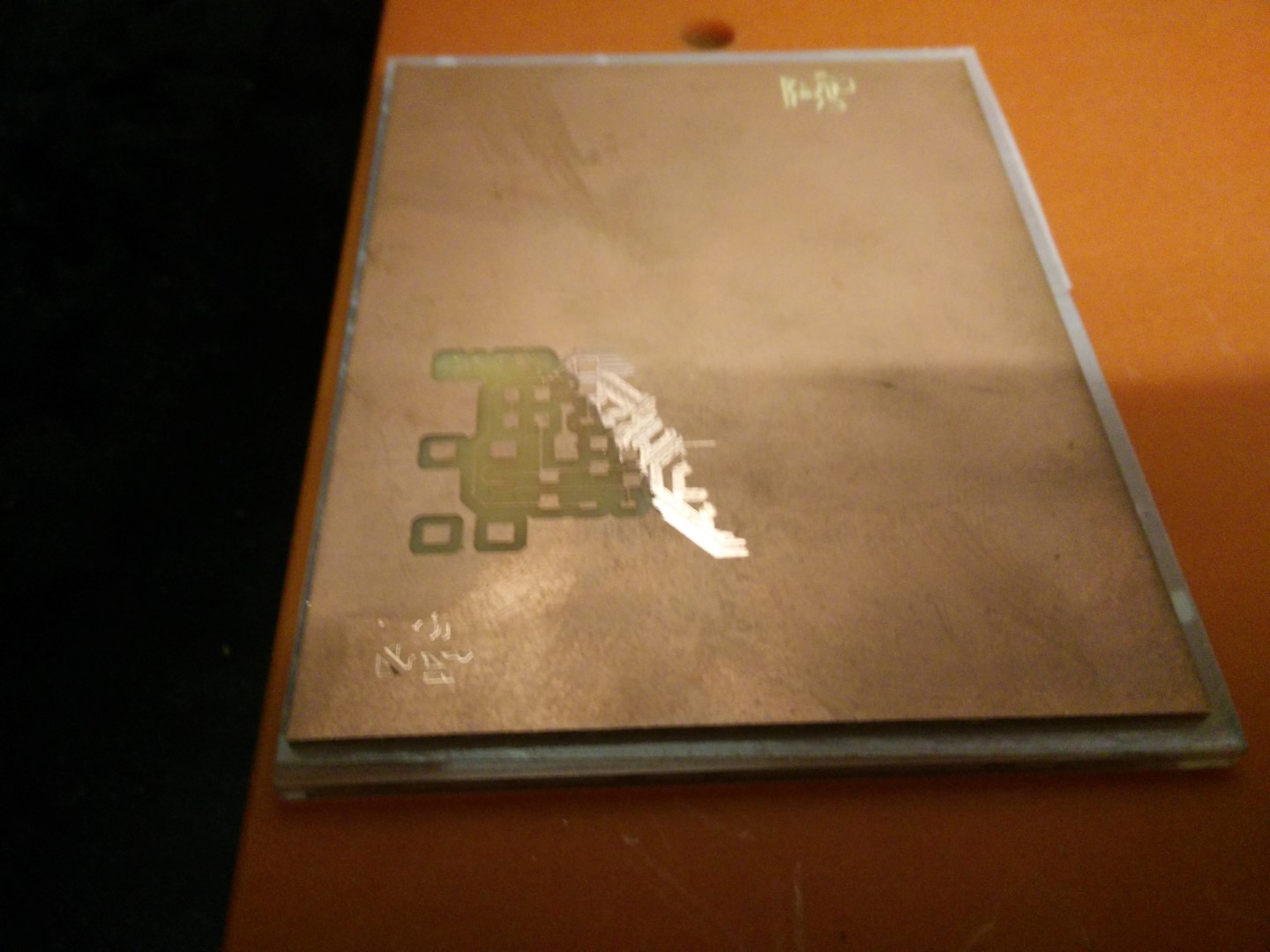
Result of testing different parts of the board and also with the 0.7mm bit.
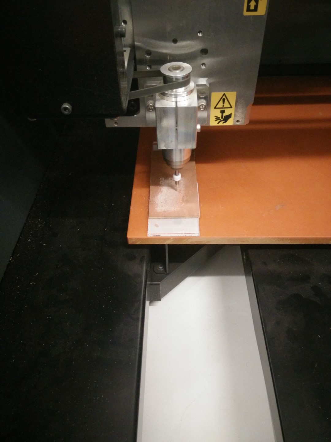
Now is place vertically over the bolts. More flat?
Not bad before cleaning, for a v bit. Still not usable
Another pass a little bit deeper and. This could be fixed and used.
The software stopped during cutting-out. Tried desktop fabmodules, but clearly missed somwthing about the coordinates. I'll try again tomorrow.
Morover, we don't use fabmodules usually and was a good way to start trying it, even though I didn't connect the machine, just generated the files to the load them into the MDX Vpanel. This is another issue to solve, as sometimes it seems to stop before finishing, at first we thought it was coming from the end of file descriptor or something like that, as the pcb traces are difficult to tell if it lacks some cutting. Then we witnessed how the cutout stopped before finishing. Seems like a problem with something on the code from fabmodules.org This is something I want to keep doing during the fabAcademy and I will come back to this page.
UPDATE! 29/02/16
Well, yesterday was able to finally make a board using 0.4mm mills. Also David updated the MDX40 firmware after seeing at the MDX support page that Firmware version 1.50 for the MDX-40A. Fixes bugs with thickness of Z0 sensor settings and ability to read H command in 3rd party CAM programs.
So I've started with the fabISP with a 0.1mm depth cut. But the surface it is not leveled at all. But what I was able to do is to use the calibrated Z0 sensor from our big CNC FRH210 with the Roland MDX40. It's a 12mm sensor, but the Vpanel only lets you enter a number between 14mm and 16mm. Solution obviously is to put 14mm, detect Z0 with sensor, then remove sensor and move the head so its 2mm. Then manually set Z0. Also, the length of the cable was not enough to reach modela's back panel, so I grabbed a stereo cable I had in hand, and I was mistake-proof enough to grab a broken bit to test the extension, being an stereo cable. I was right and wrong, because it failed and had to change the tip and ring because modela reads the tip of the jack. I'll get parts to make an extension cord.
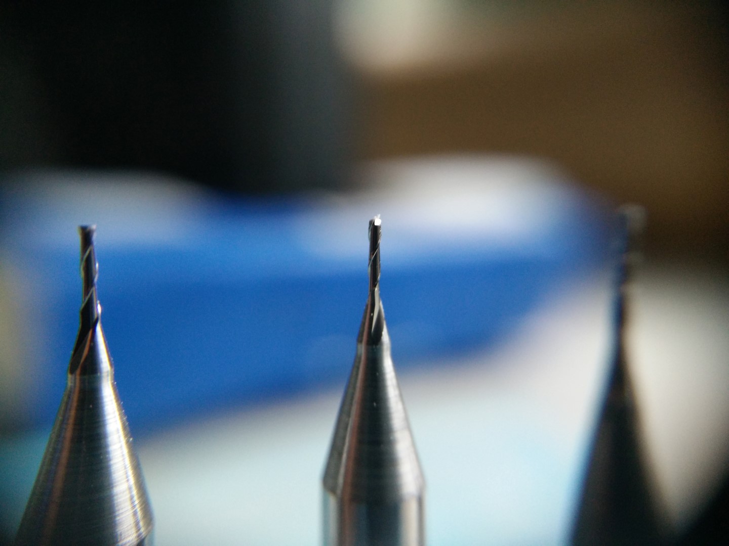
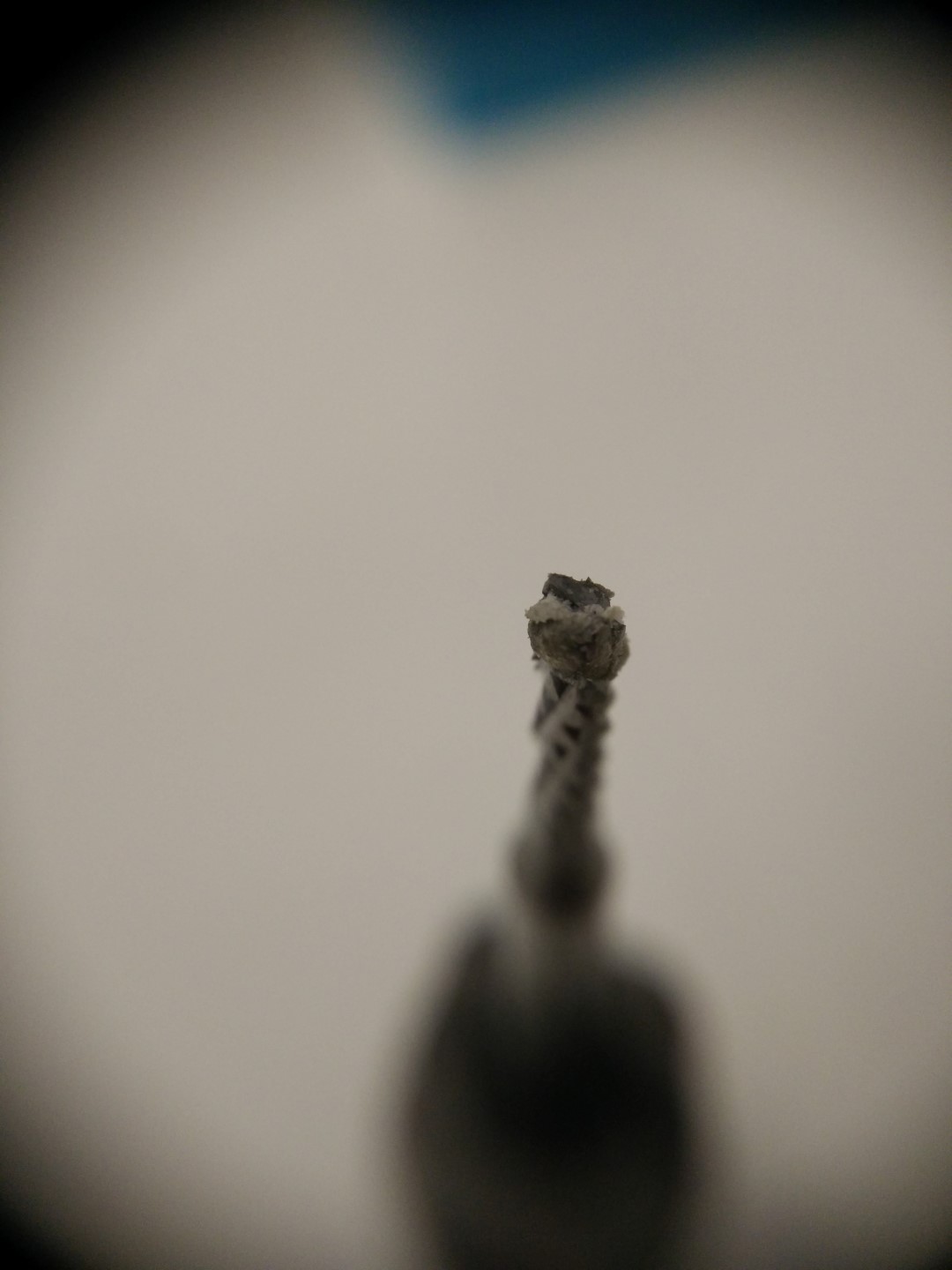
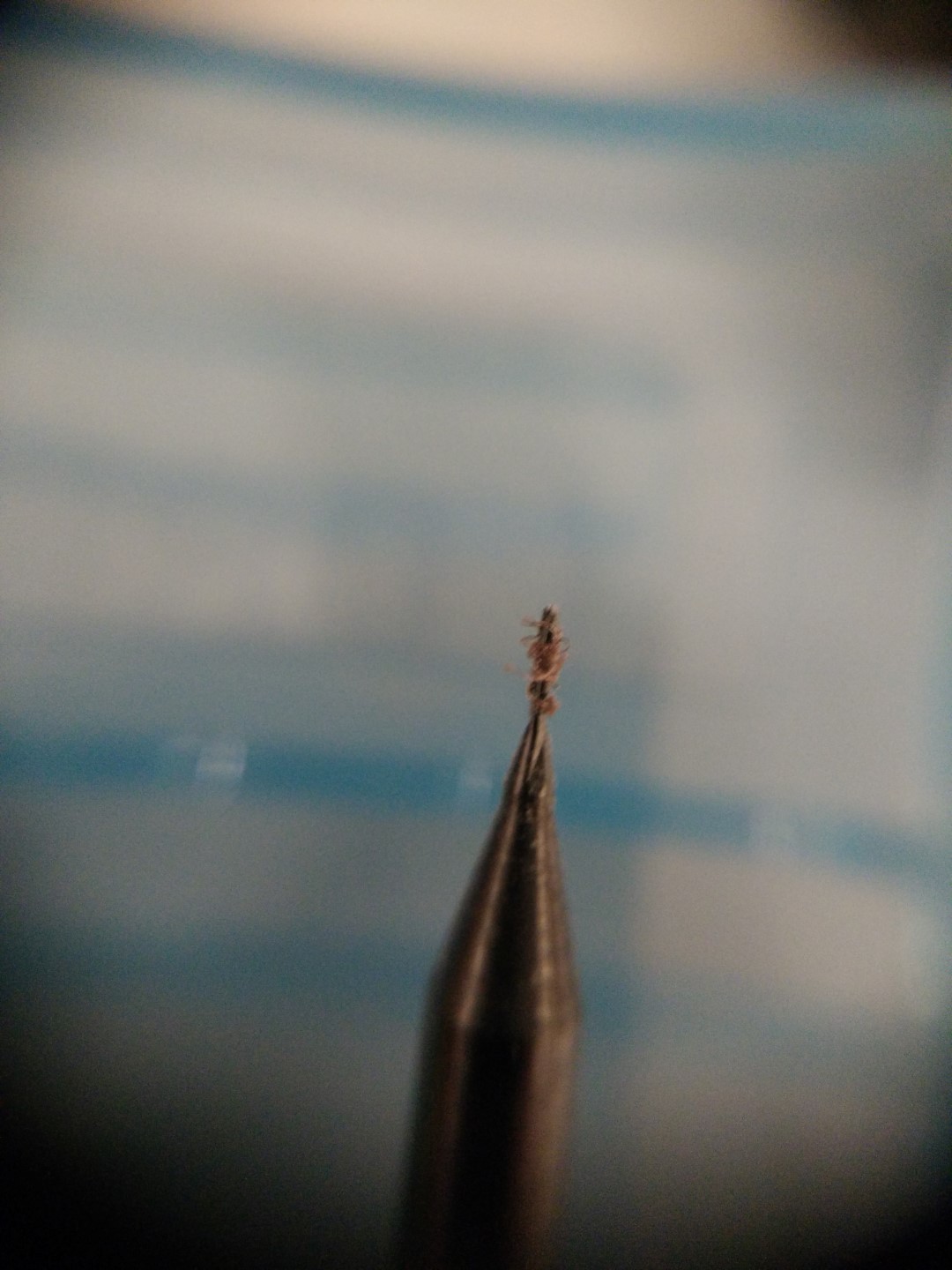
Detail of the 0.4mm bit
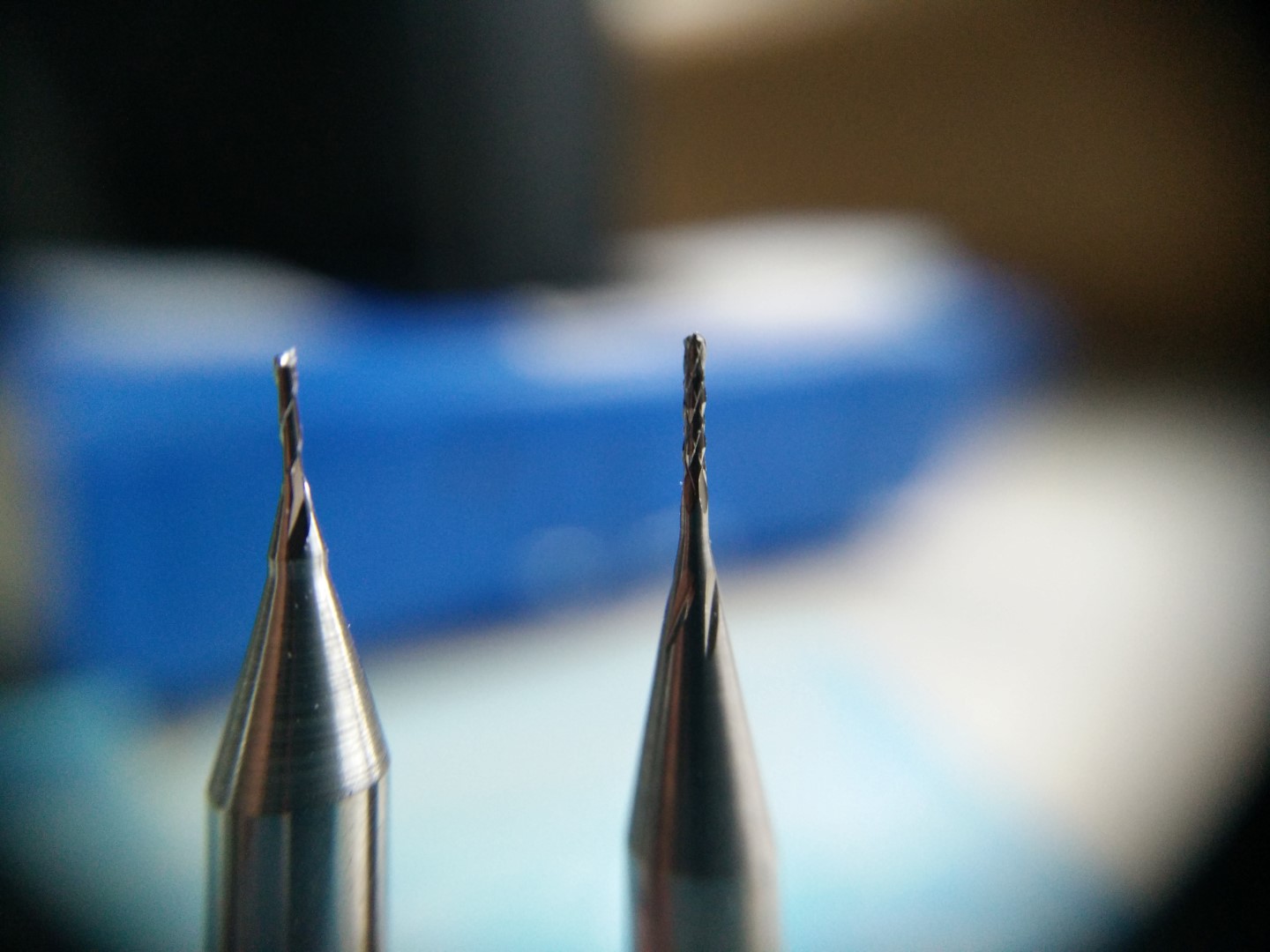
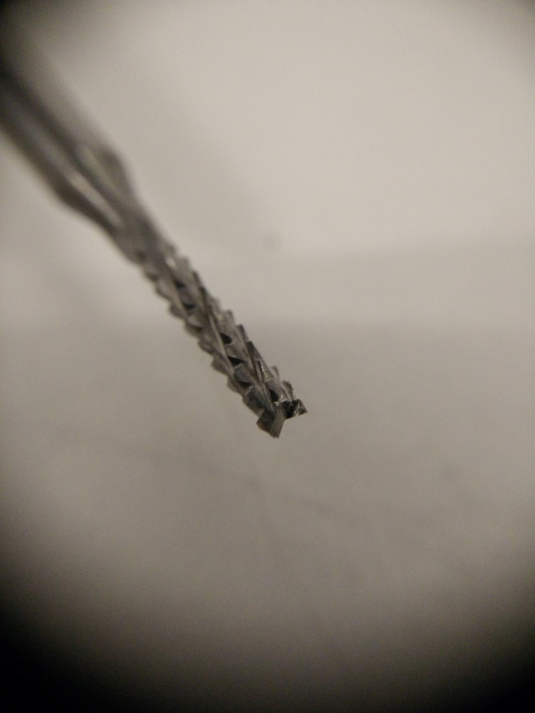
Detail of the 0.5mm bit
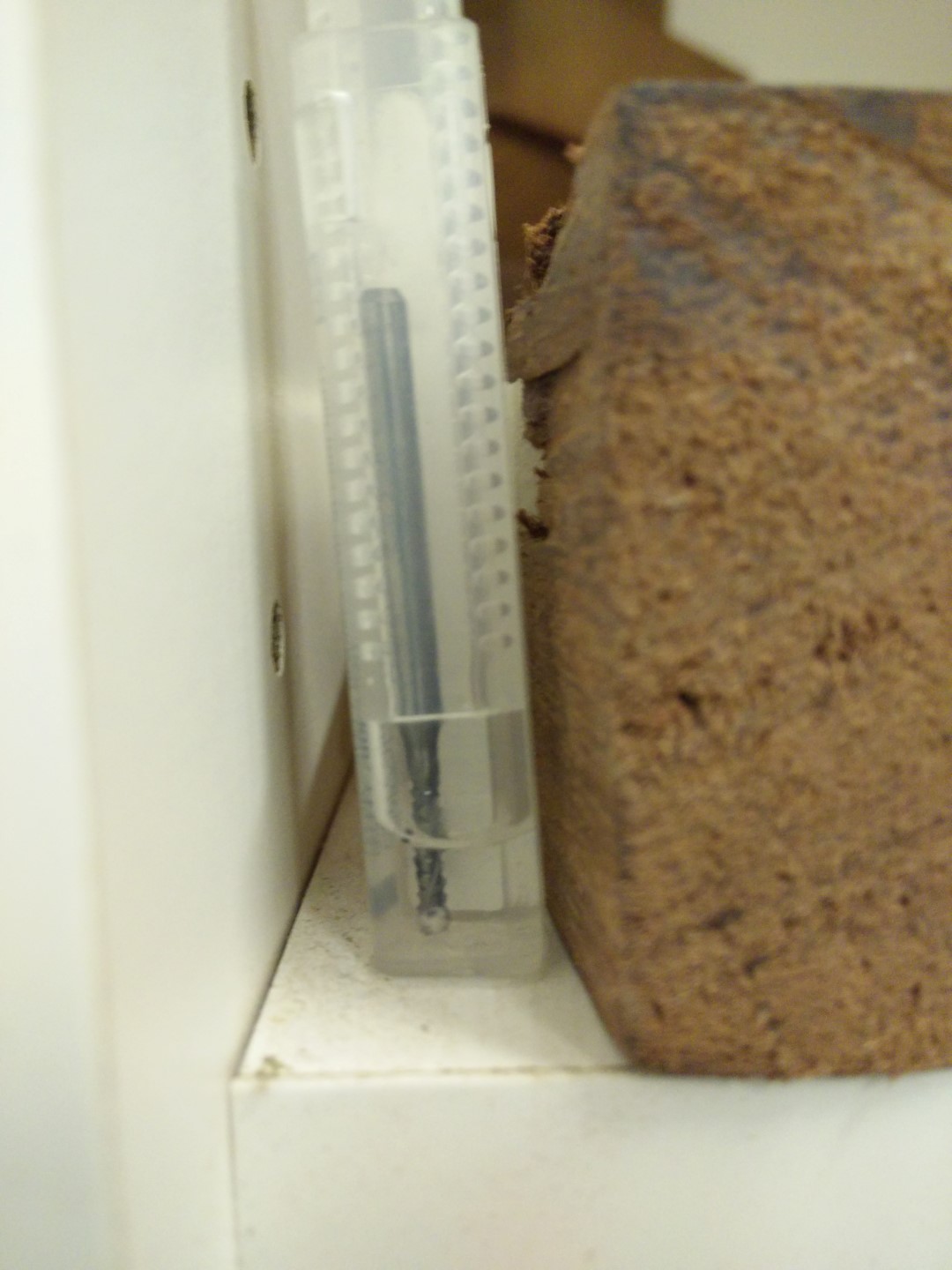
Using the Z0 sensor
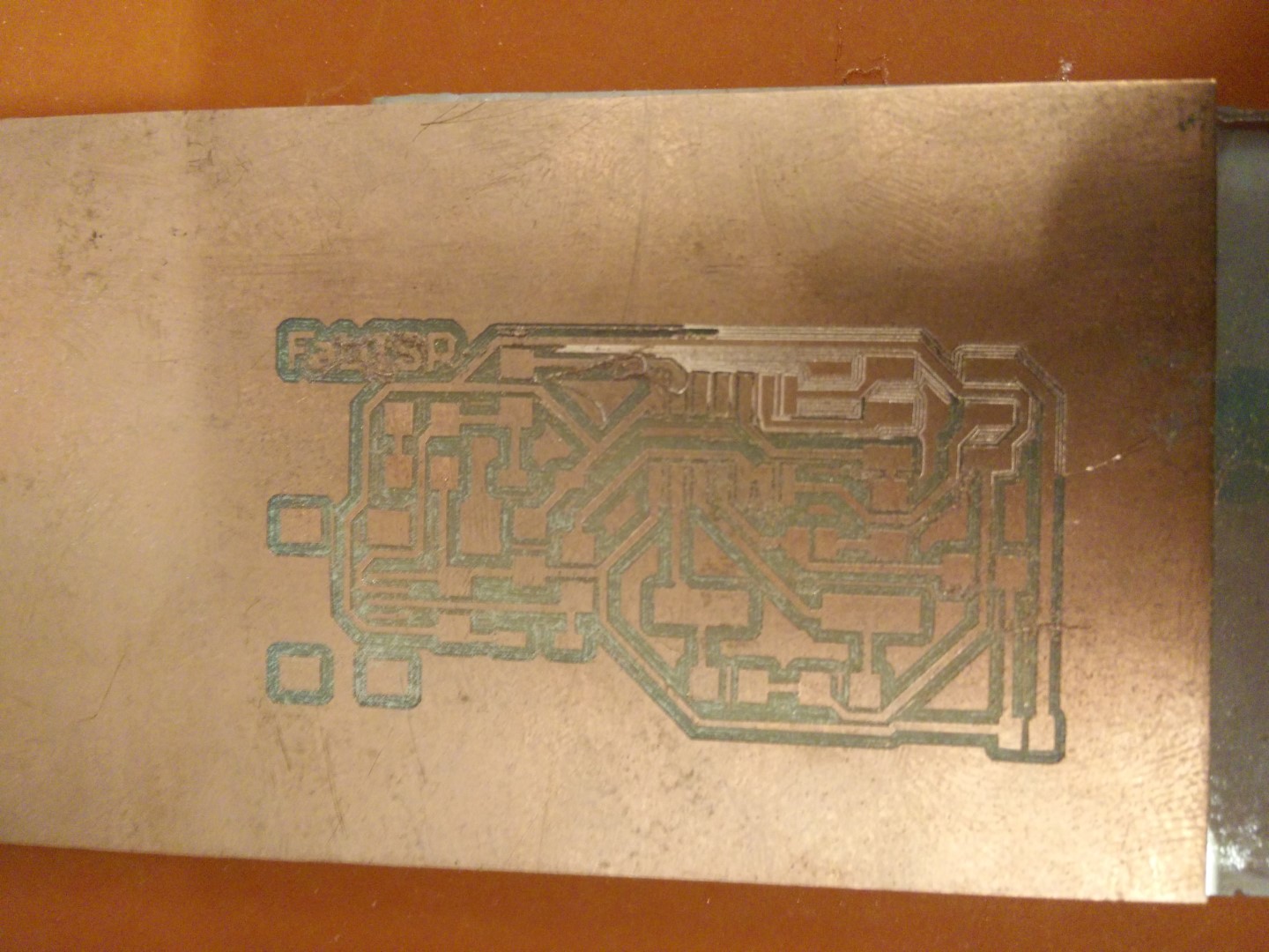
Bed completely off-level, 0.1mm pass
0.2mm pass, seems like constant slope
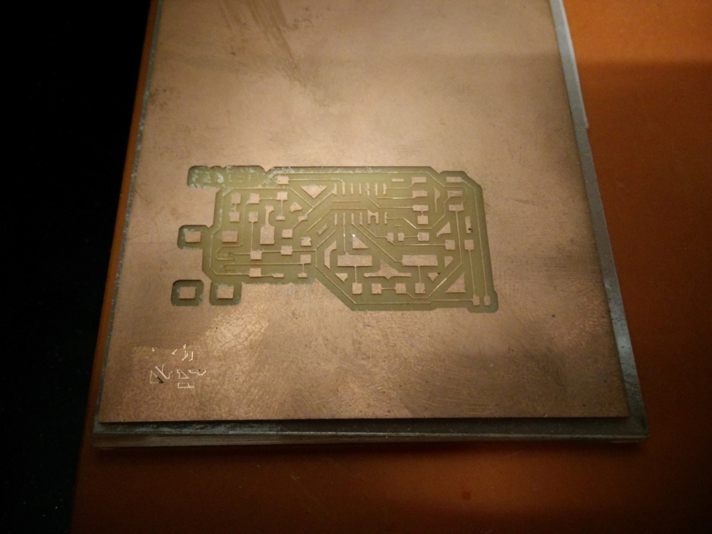
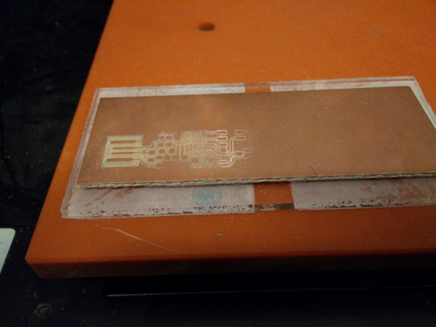
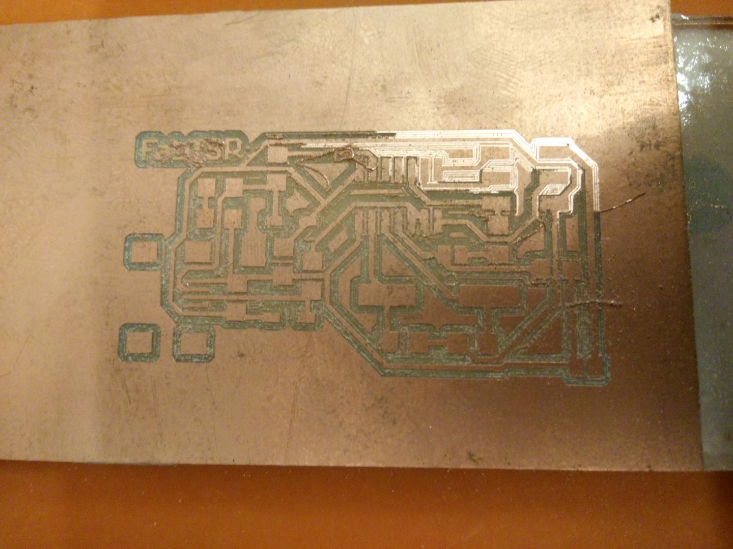
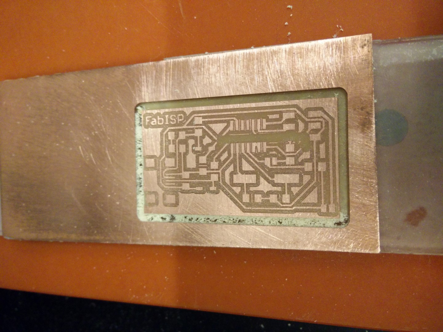
0.32mm pass, all pads semm ok, FabISP logo is ripped and so are a couple of the usb connector pads
Milling it out with a 2mm routing bit
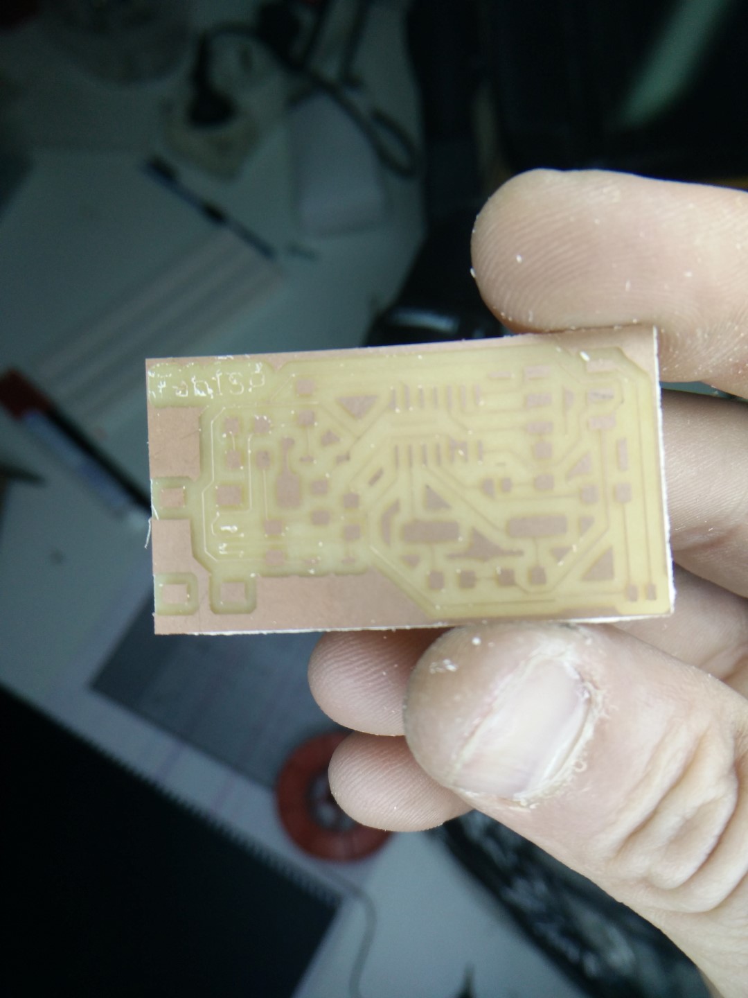
Could be used but I can do better!
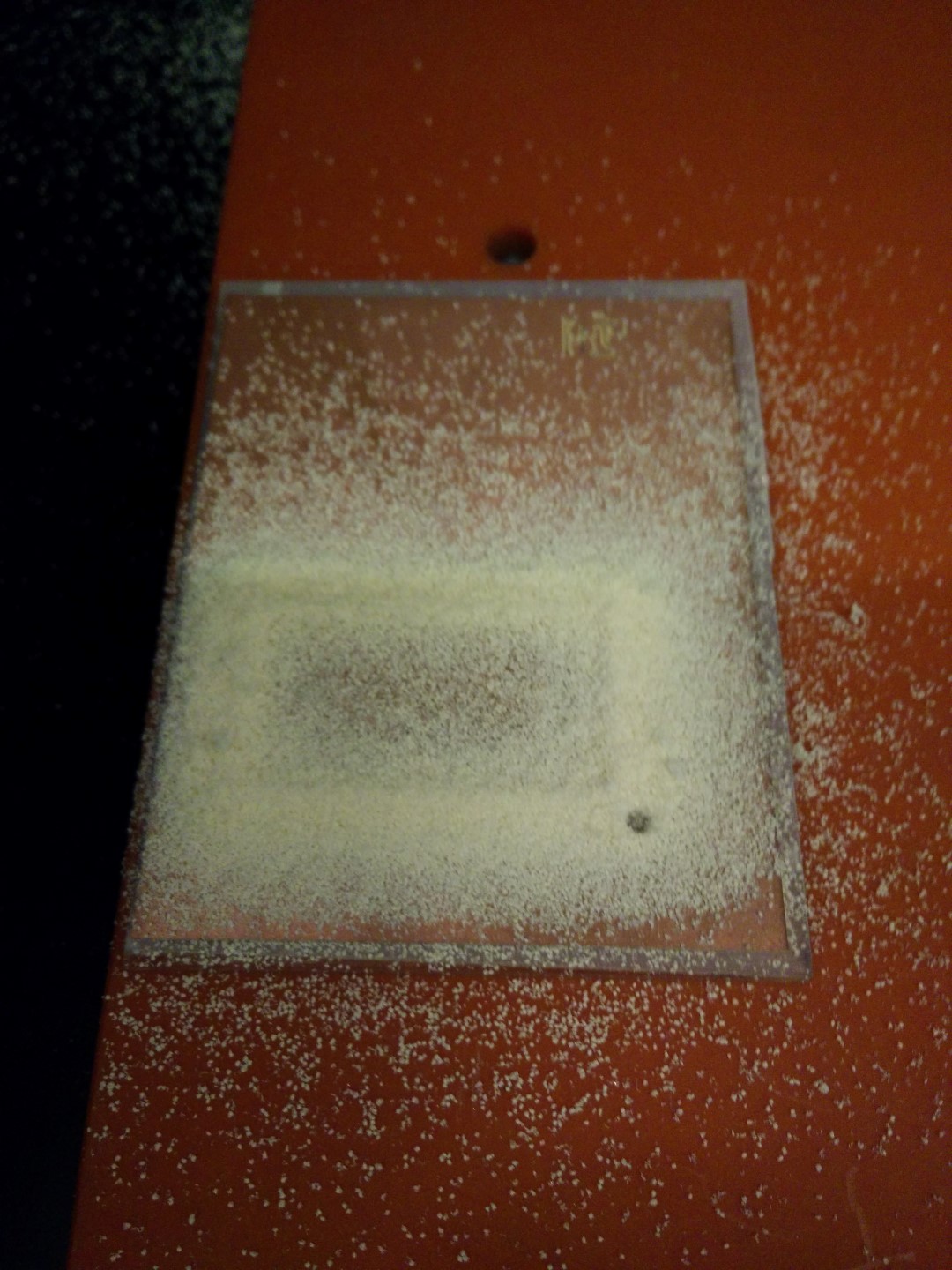
So, took a larger PMMA piece and flatten it 0.5mm
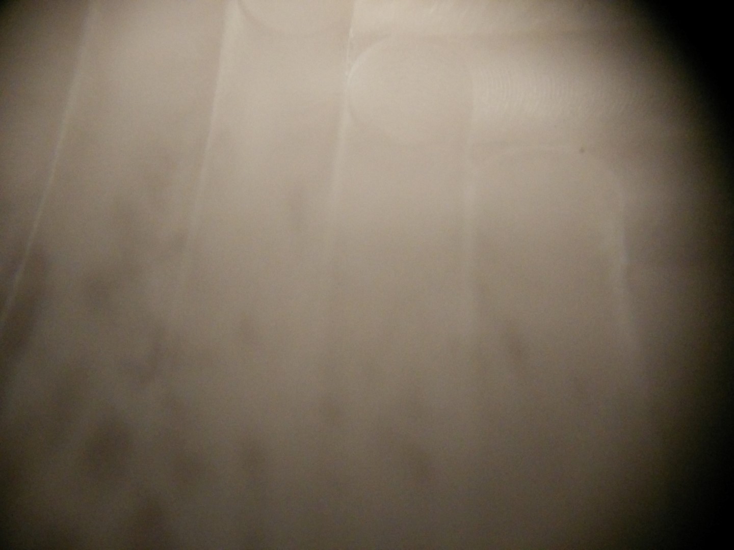
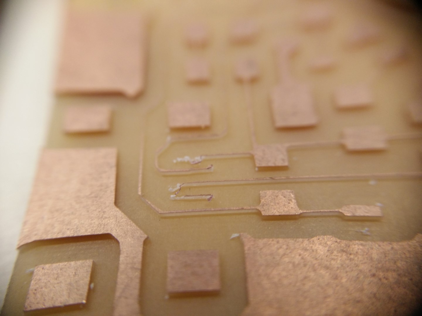
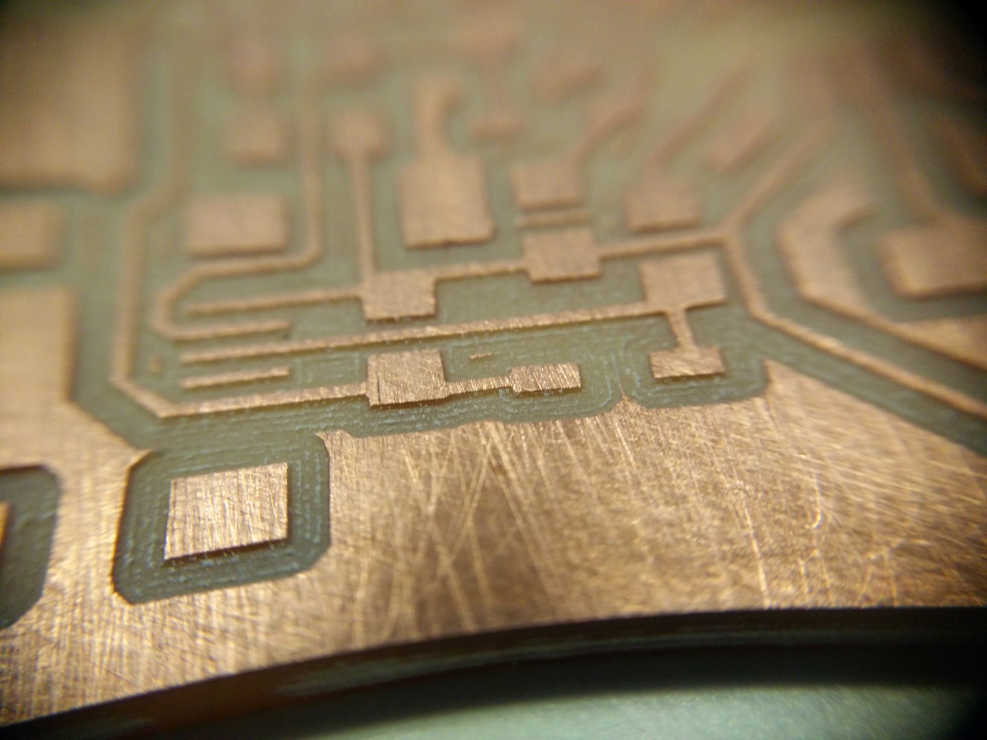
Macro detail of the flattened surface
Now this looks good!
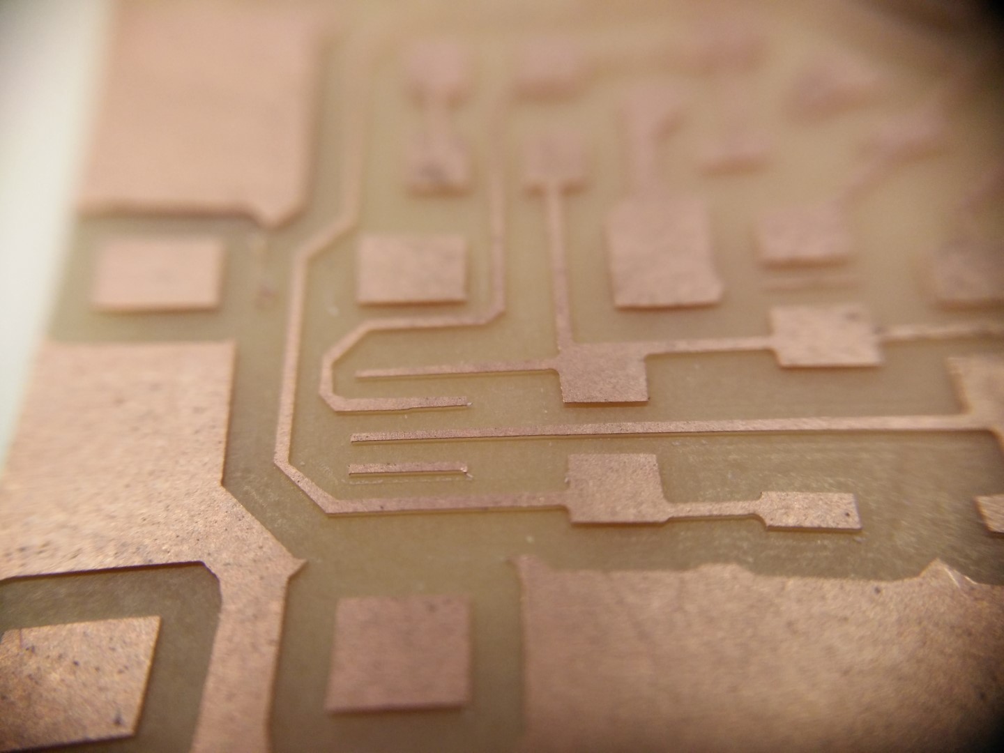
This would had been a bit of a struggle to solder. Notice how deep are the traces here
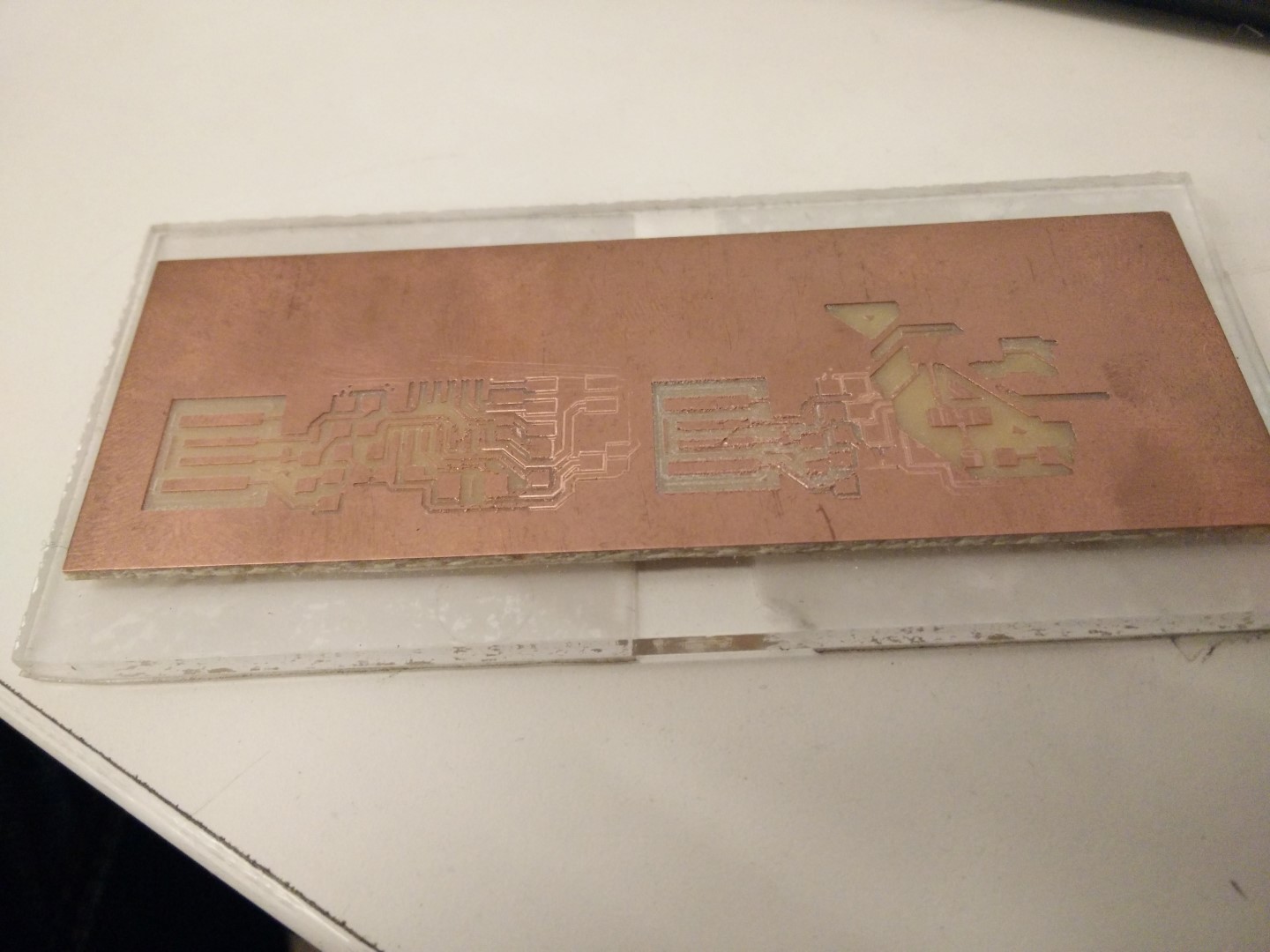
This is a macro detail of the first board machined with the V-bit
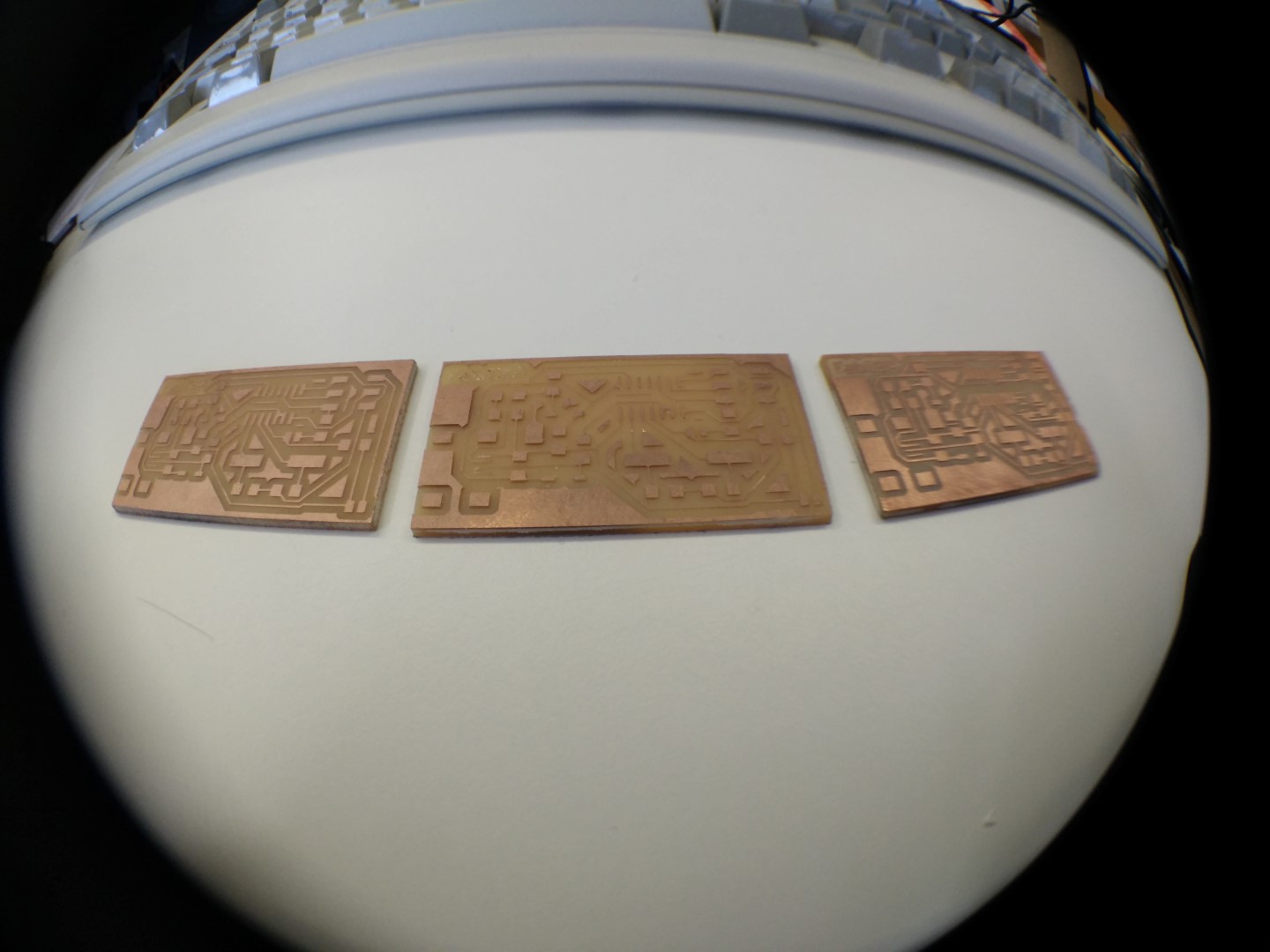
Left to right, newer to older
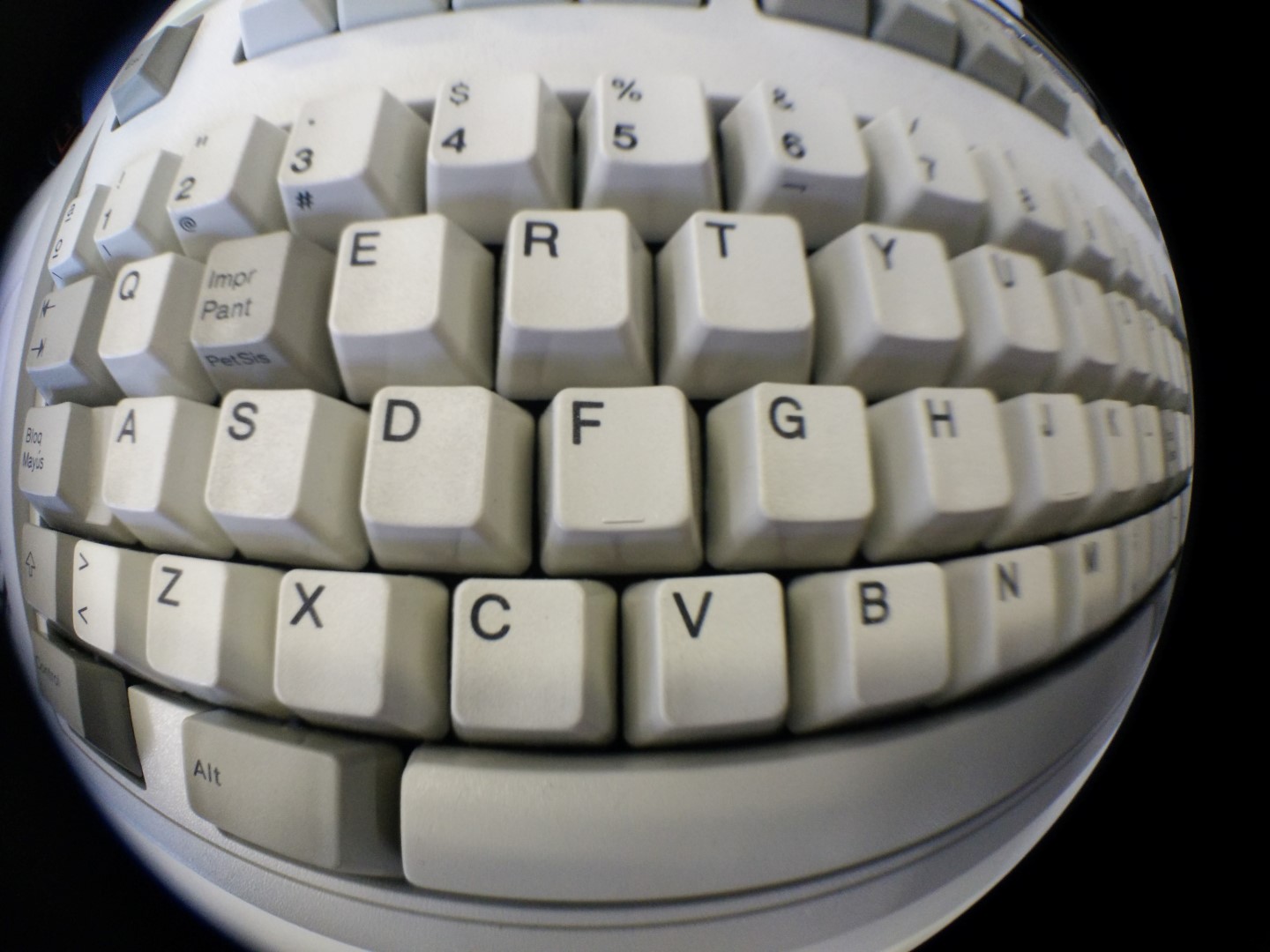
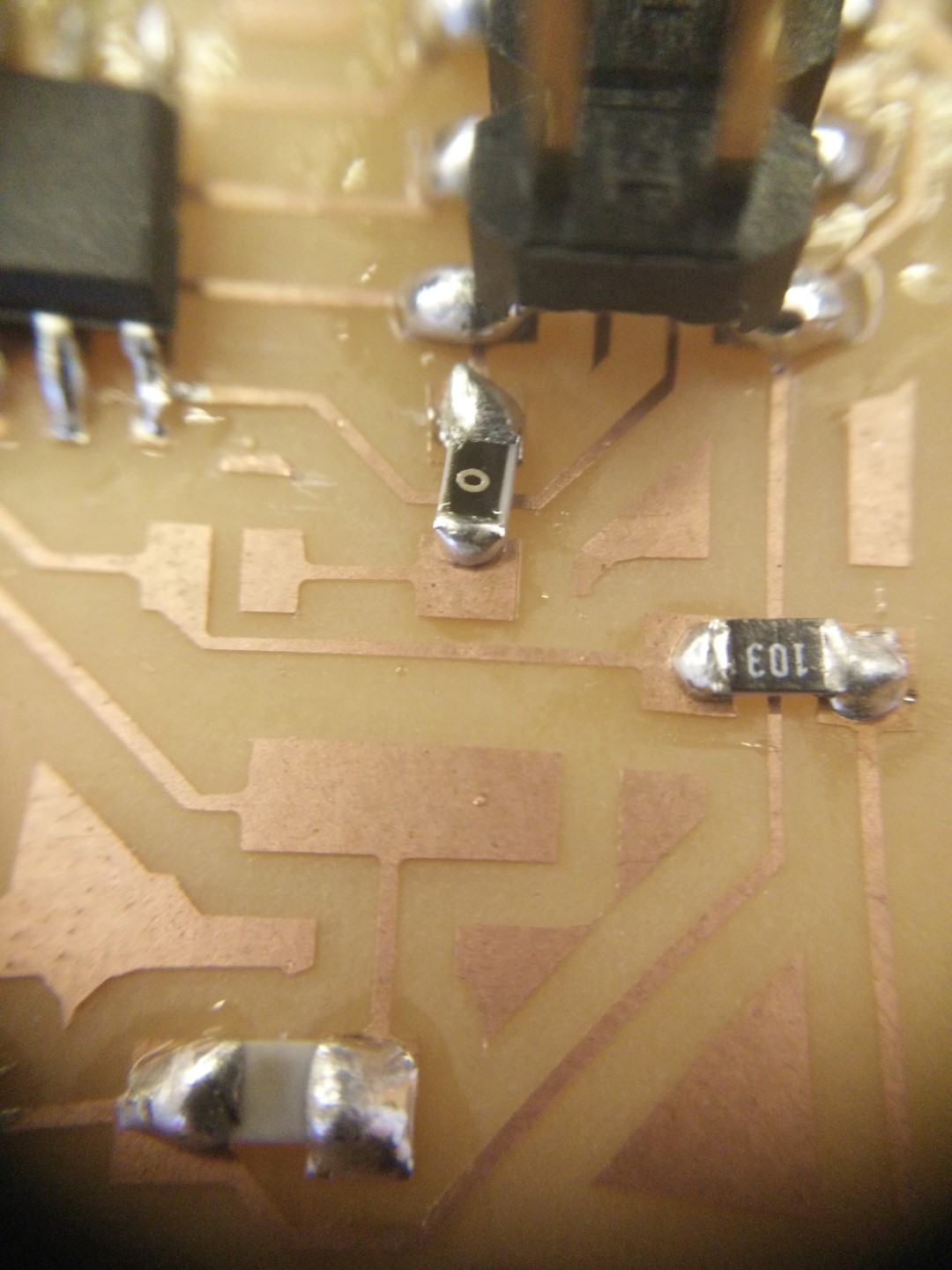
Fish eye is fun, but macro is comming in handy. All fotos here are taken with a phone camera. You can get those lenses on ebay or aliexpress for around 5€.
It was some time ago since I soldered SMD. Not my best solder for sure. Lots of solder!
When I finished cutting out the PCB, there was a lot of residue from the double sided tape on the tip of the mill. So I picked up a mill box and poured a little bit of acetone just to cover the tip of the mill. Today in the morning I just shaked it a little bit and it came like new.
By the way! I don't have a good phone camera, but this were made with those cheap clip-on lenses selling on bazars (online bazars I mean) I got a 3 pack for about 4 or 5 EUR and it includes fish-eye, wide angle and macro lenses. Fish-eye is funny, but macro is really cool to show Neil your solder skills and other fine details