Final Project: Process
Below you will find my dictation, notes and documentation about the processes I went throught with regards to completing my final project: Bat Signal Night Light with Reflecting Mirror. Each of the steps and processes will be covered in seperate sections. A link at the bottom of each section will take you to all of the files that I created that section.
Batman Laser Cut Light Box
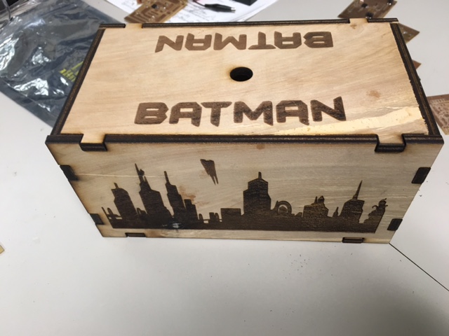
I created box using InkScape for the design and the Epilog Laser cutter for cutting and rastoring the wooden tabbed box out of birch plywood as well as a ruler and caliper for sizing my box. I purchased the piece of birch at Lowe's. I engraved the skyline of Gotham City on each of the long sides of the box and the Batman logo on both of the short sides of the box that had a small 0.25 inch box vectored cut out for a magnet that has a casted batman logo with a magnet too for attaching it to the box. Lastly, I engraved Batman in large letters across the top of the box. The box itself houses all of the electronic parts as well as has the spotlight attached to the top of the box. Below are the images of the design and the completed box:
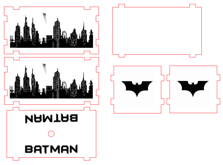
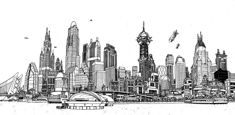
The following links are to images I might use for the Gotham City skyline and the Batman logos:
I did forget to create a hole on the side of the box for the arduino wire. I used a drill and drill bit to fix this mistake during assembly.
This is a link to access the files created for this section of my final project.
Molding and Casting of Magnetic Batman Logos
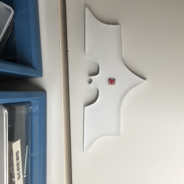
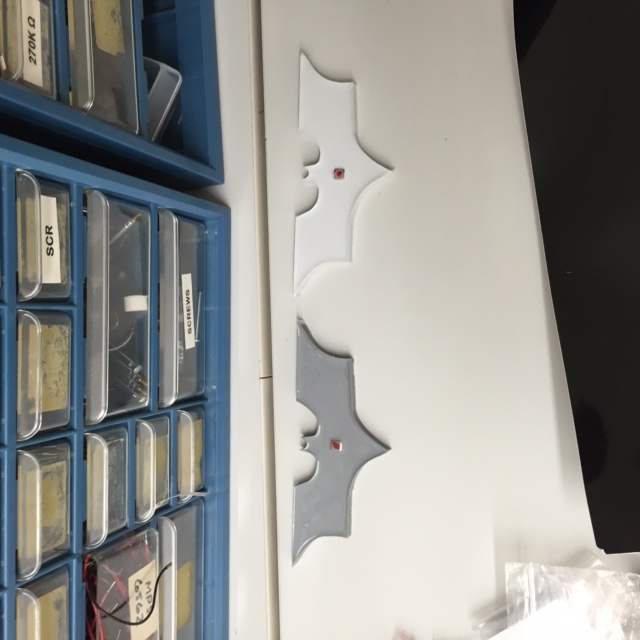
I created two batman magnetic logos that have small 0.25 inch earth magnets in the center of them. You can purchase these earth magnets pretty cheap. I used a total of four of them. I used Molding and Casting exercise parts for this section.
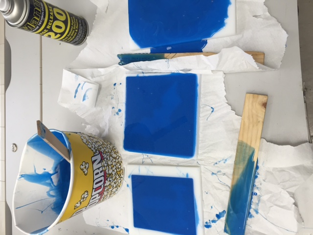
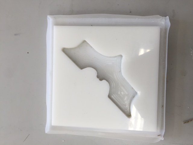
I used the Smooth-On Mold Star 15 Slow Platinum Silicone Rubber. I mixed a 1:1 ratio. I also used Silicone Ease Release, which was sprayed over the mold as well as during the casting process. This allows for the matieral not stick to the point it will break or rip. Next, I poured the mixture into the box to create a mold and waited until the following day for it to cure. You can see the photos below of this process.
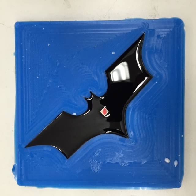
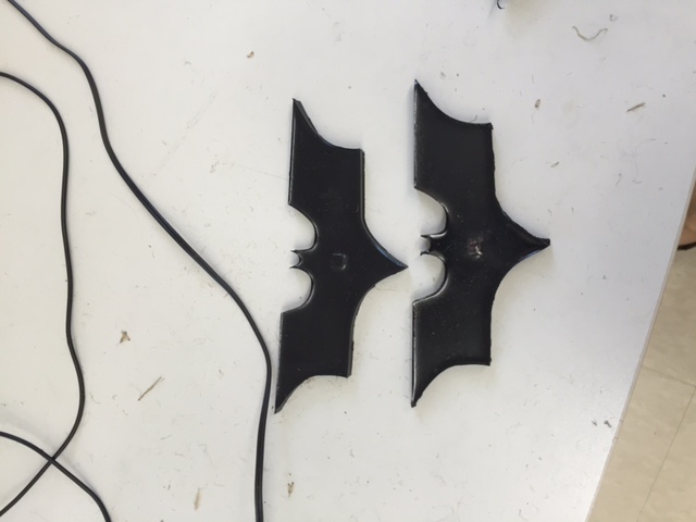
Next, I mixed the plastic harding material to make a second batch. I used the Smooth-On Casting 305 I attempted to use coloring, but it did not work very well due to it being white. I ended up spray painting them black.
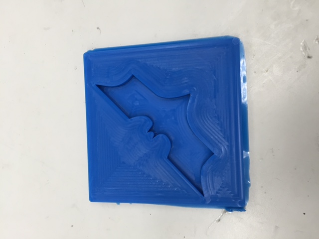
Below is the casting and molding portation that was completed using the piece creating using the ShopBot from the Casting and Molding exercise. The original part was created using Aspire. You can see the magnet in some of the images, which I marked with a red Sharpie to know which side is which.
Files
Composite Logos on a Mirror
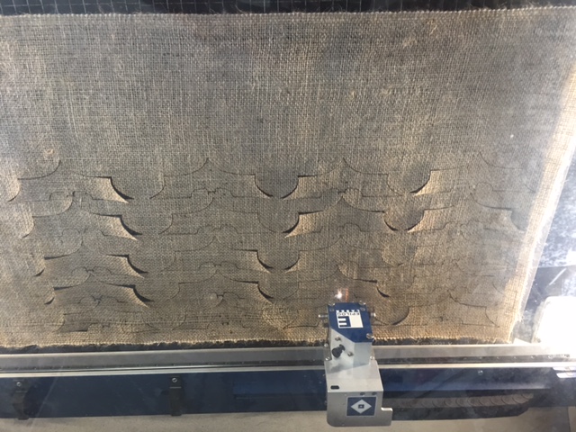
I created four composite batman logos out of berlap that were connected to the four corners of a mirror. I used the materials and parts I created from the Composites exercise. I followed this process exactly the same way and created foour of the batman pieces. The images below show the process:
Aspire
I used the mold from the exercise 14, which was made using the ShopBot and Aspire.
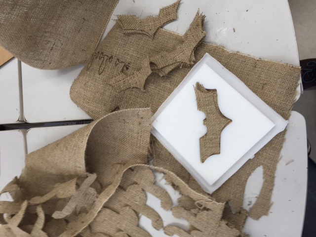
Burlap Batman Logos
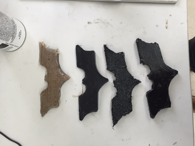
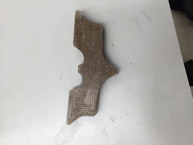
I cut out another batman logos out of the burlap once I had the exact fit. I will layers this with resin to create a compisite shape. You can see this portion in the images below:
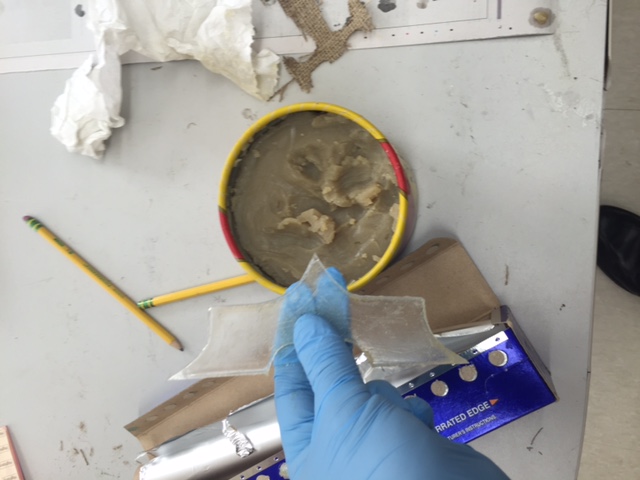
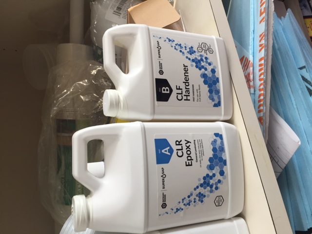
Resin Process
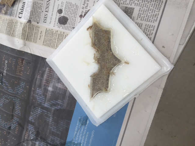
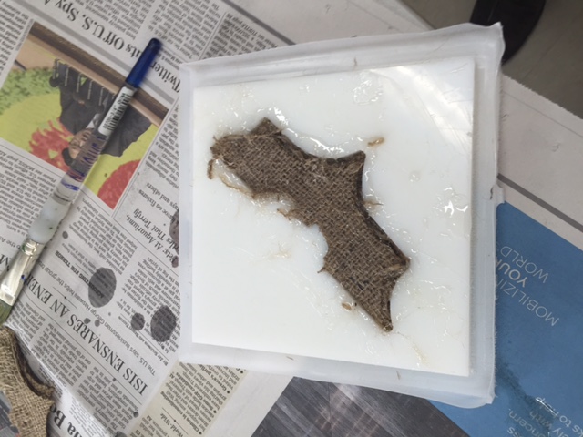
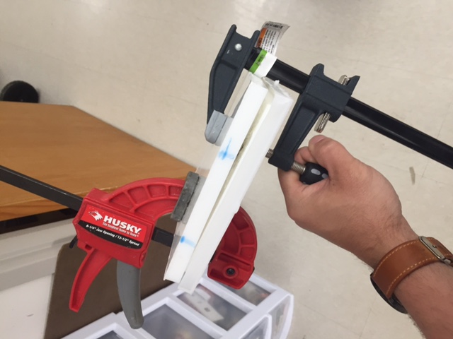
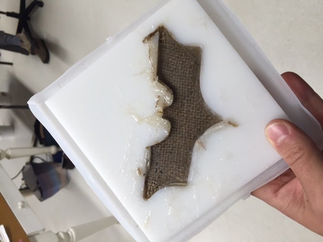
The resin was mixed using a 2:1 ratio. After mixed the CLR Epoxy - A with the CLR Hardner - B, Tom created a sqaure pool for the resin to be in out of aluminium foil for us to use to dip our burlap pieces. I used wood wax to lubricate the mold and than used a pain brush to get ride of any clumps in corners and etc. I dipped and saturated the burlap pieces in the resin and placed them in the mold. Due to using the mold, I did not have to dip each piece, because, I could push down on the burlap and the resin would pool up through the new piece saturating it. After placing 12 pieces of saturated resin, burlap togther, I pushed down hard to make sure there was not space in the mold. Next, I took one of my casts of the batman logos from the Molding and Casting project and waxed it, so I could use it to push down on my burlap pieces. Finally, I used a inverse mold to clamp down on top of the batman logo. By clamping it all together, it allows for pressure. We left out the leftover resin to use a timer to be able to see when our compistes would be dry and hard. After the compisites were finished, we pulled them from the molds and trimmed the extra matieral the ran out of the mold. I highly recommend wearing a lab coat or something like it as well as gloves, because, this process is messy and very sticky due to using the wax and the resin. Below are images of this process:
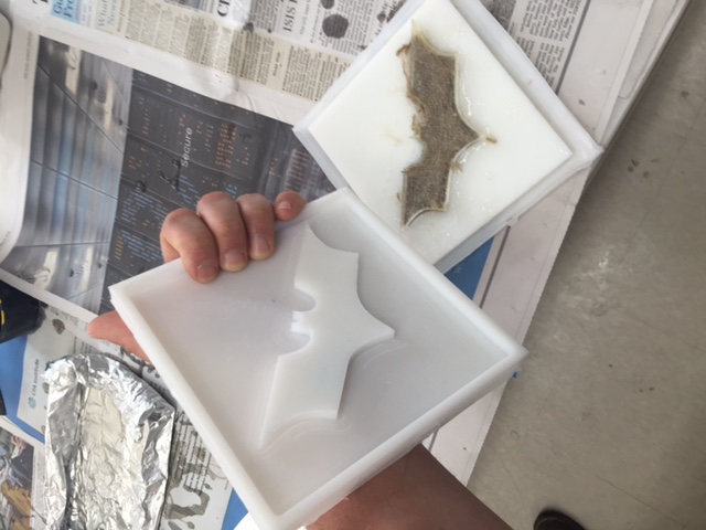
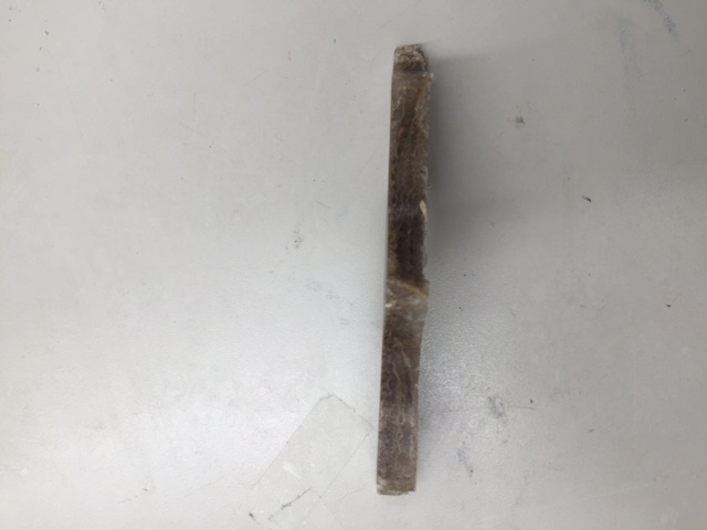
The resin took about 3 hours to set up. Once it was finished, I used a flathead screw driver and needle nose pliers to pull out the composite. Below are the images of my finished project:
Attached to the Mirror
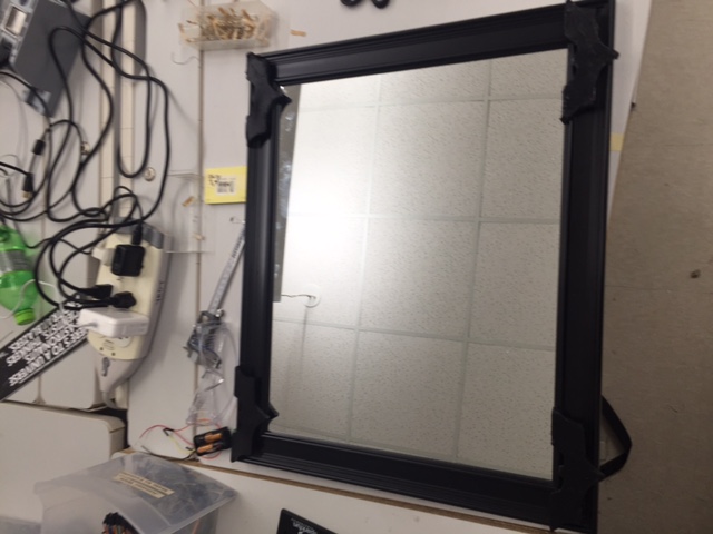
I glued the batman compiste logos to the four courners of the mirror. The image below shows this:
Files
3D Printing
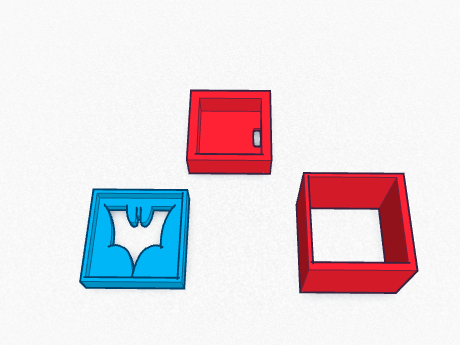
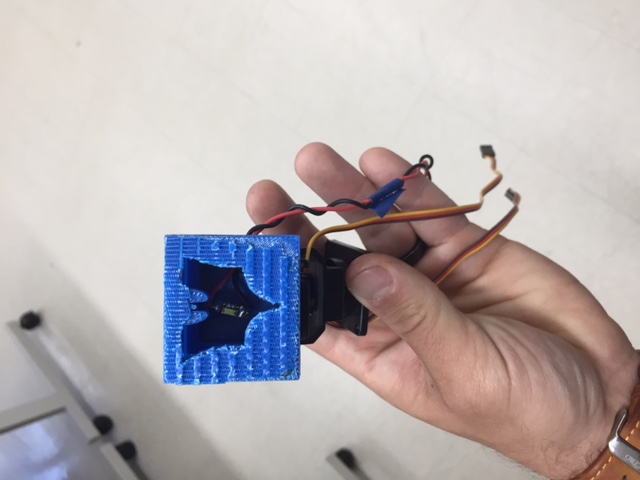
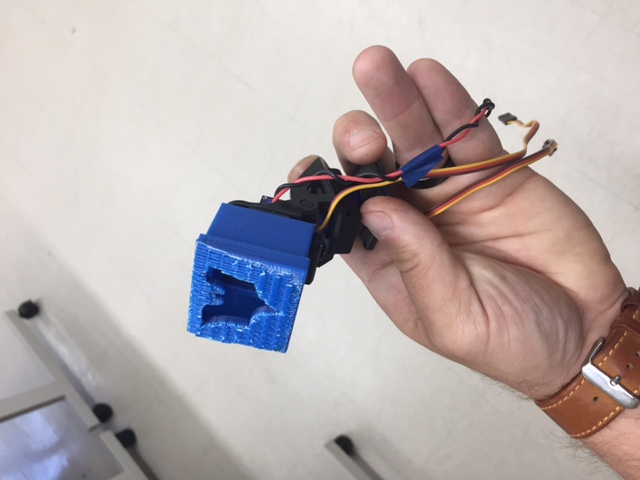
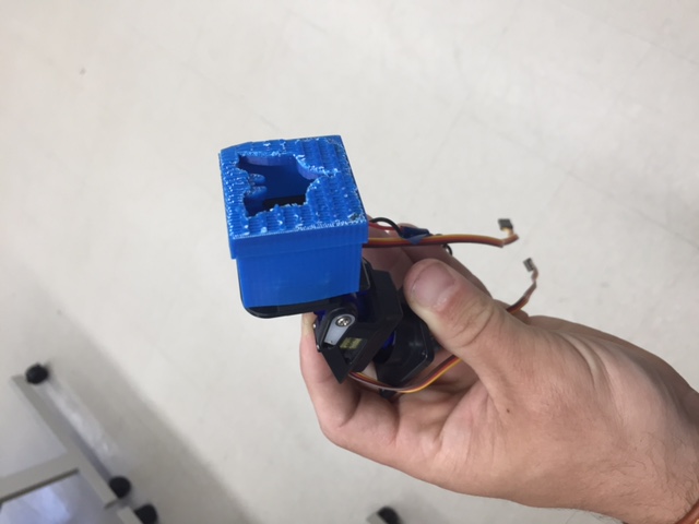
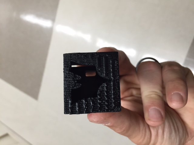
I used TinkerCAD and a 3D printer to design and print my batman spotlight housing box. I orginally worked on this during the CAD exercise and the Scanning and 3D printing exercise. I used a cailper to measure the sizes of the servo panning arm and designed the housing based on the deminsions. I than spray painted the parts flat black to match everything else. Below you can see images of the design:
File
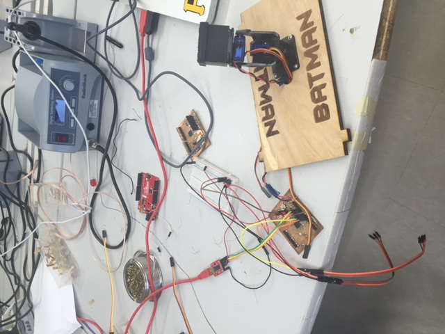
Electronoics - Fabduino
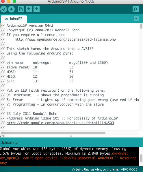
I plan on using electronics (IC) to control the servos and the spot light using a Fabduino.The design I am using orginal came from satshatkit. The satshatkit files were the foundation for the changes I made to my board in Eagle. I cut out the board and soldered it; I actually did this twice due to my board not working. My first board GND out everytime I connected it to anything. In other words, I could plug the GND pin into almost any pin on the board and it would GND out the board turning on the power LED. I attempted to burn the bootloarder using a Arduino by connecting, which you see in the image below, but it did not work:
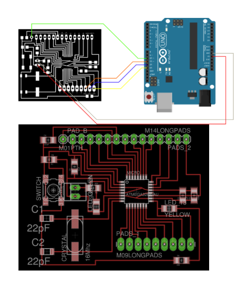
I did this through connecting the correct wires using the image below and making sure to use the correct port as well as the ISP, than you click burn bootloader. If it works it will work rather quickly and you willg et a finished burning bootloader in the IDE, but if it doesn't you will get an error message explaining that it has not connected to the board and it will attempt this 10 times. Both of my boards below did not work:
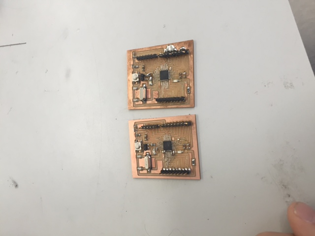
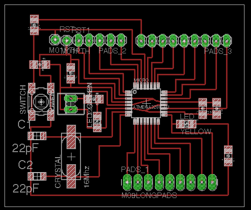
I attempted to this twice by building two boards, with zero success. One of the baords was my design changes and the other was the orginal board. I changed the reset and added a GND pin based on Ian's design. Ian helped me with this process. Also, you need to make change to the orginal design with regards to the trace running under the two capacitors, because, it will run into the side of the capacitor. Below are the images of the boards I made and the eagle files of my changes:
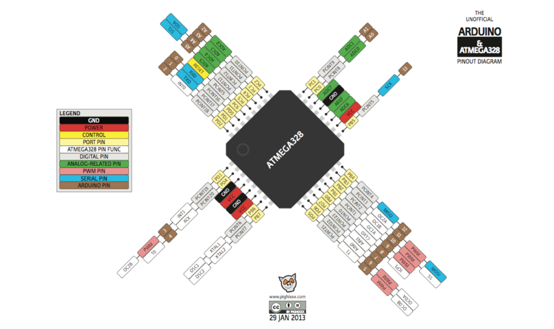
The image below of the chip is helpful for understanding the pin connections:
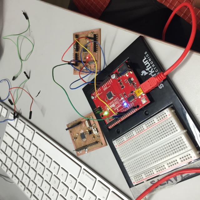
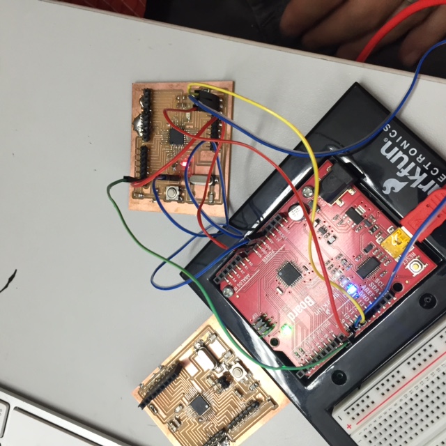
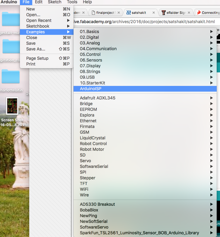
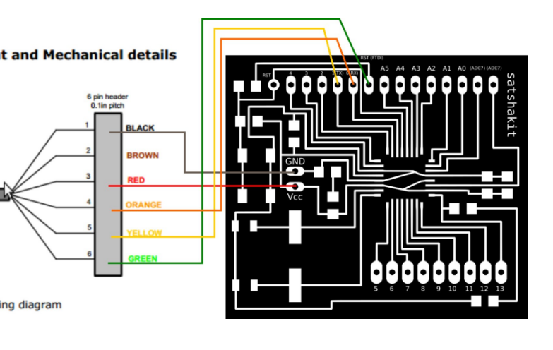
Final, I got the board working. Terence showed us that we missed over a specific example code that needs to be loaded first from the Arduino IDE called ArduinoISP. The following link is helpful for trouble shooting: Trouble Shooting the Satshakit. This code will give your board the ability to work. The images below help to show this process as well as how to wire it:
Files
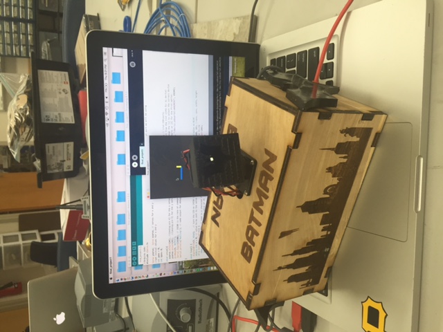
Arduino IDE and Processing
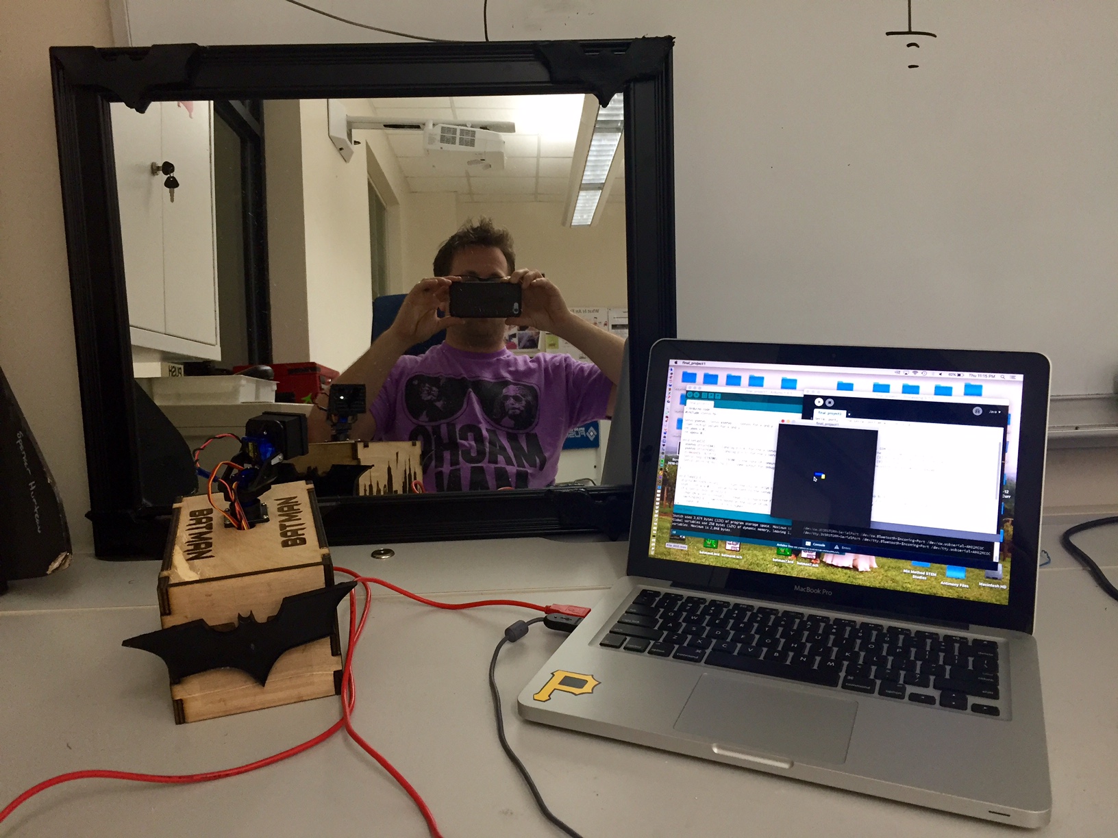
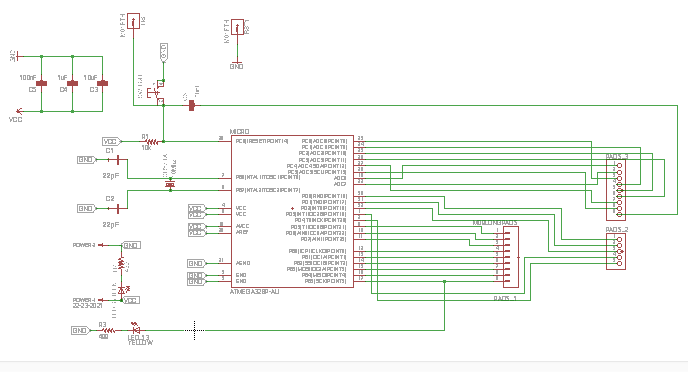
I used arduino IDE to program my board as well as processing to be able to interact with it. I used an Instructable by Biotech75 to help with the arduino and processing codes. I used this persons work as the foundation for my work and made changes along the way to it. In the ardiono code, I used the schematic of the ATMEGA328p to identify the analog pins. I connected the servo pins to A4 and A5. I used a basic arduino servo image to help connect the correct wires. In the arduino IDE code, I change the the pins to A4 and A5 as well as I added the pinMode(5, OUTPUT); under the void setup and digitalWrite(5, HIGH); in the void loop. I made changes in the processing code to the sizes and colors of the rectangles. When I first upload the code, one of the servos did not work, which did give me promise. After some trouble shooting and trying different pins as well as different servo motors, I discovered that one of the servos was broken. I replace and the project worked. The working from Interfacing and Application Programming exercise taught me a lot, which helped me complete this section of my final project.
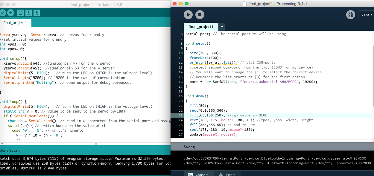
The servo and LED light were output devices. These were controlled by the code. The servo was controlled by the mouse, which is an input device. You can see all of this in the video below:
Files
Mechanical Attachments and Glue
I used a variety of mechanical attachments. I used the magnets to hold the castes to the box as well as screws to hold the adafruit panning servo arm. I used glue to hold the box together as well as the composites to the mirror.
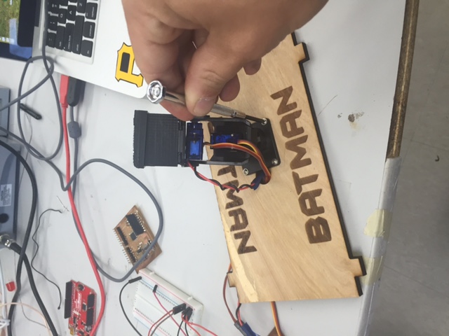
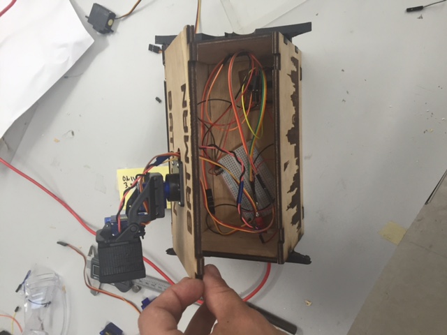
Assembly
I took my time assembling everything together into the box. I placed the board, breadboard, and wiring into the light box and attached everything together. Below you can see this in the images:
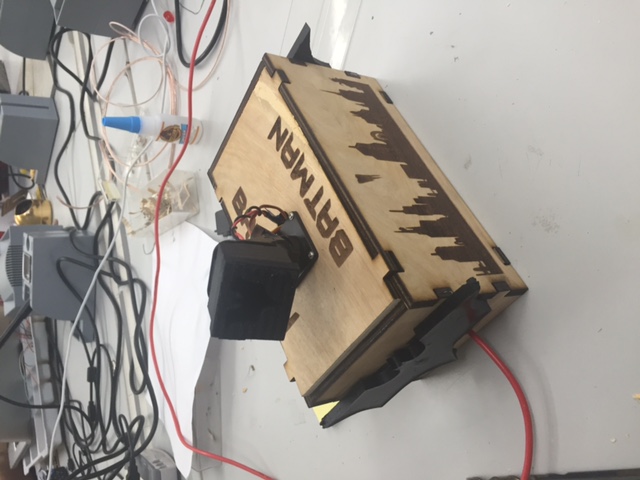
Final Project