Interface and Application Programming (May 18)
Process
Below you will find my dictation, notes and documentation about the processes I went throught with regards to completing the Interface and Application Programming exercise. Each of the step and processs will be covered in seperate sections. A link at the bottom of the page will take you to all of the files that I created for this exercise.
Research and Development
I first begin researching prior projects and installing software. I followed the lead of a former student from Fab Lab Montery, who did a similar servo board project. Next, I installed Processing as well as download the Firmata library for Arduino IDE. This also come on the Arduino IDE software. Furthermore, I used the Processing and Arduino tutorial for learning how to combine these two tools as well as downloading necessary libraries. To configure the processing library you need to use specific functions and methods for the serial library.
Arduino and Processing
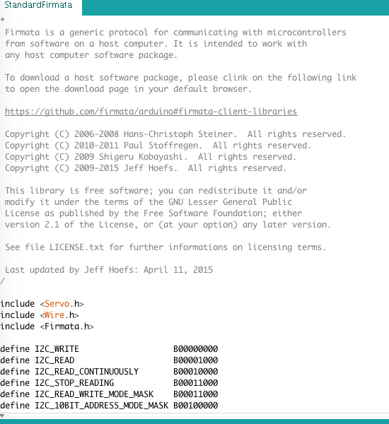
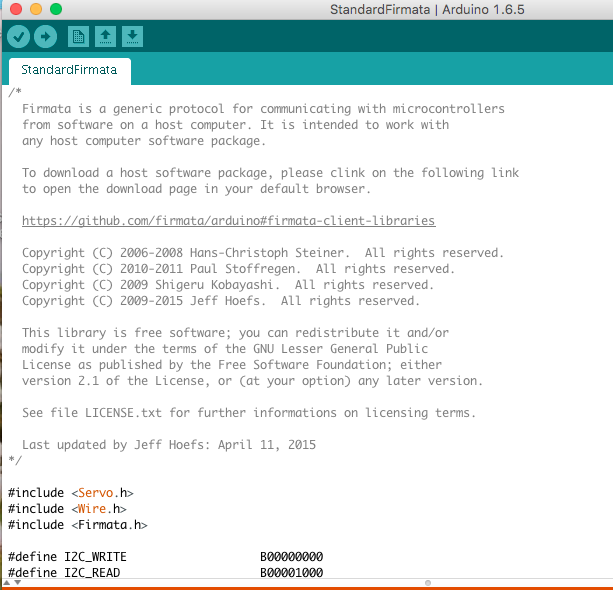
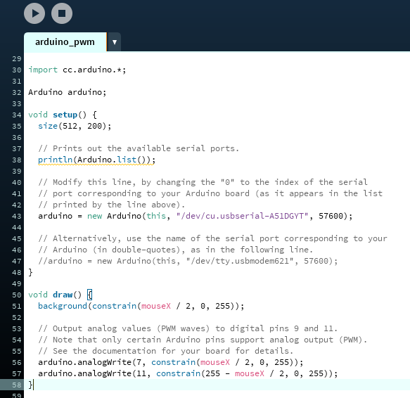
I began this coding journey by opening the Firmata Arduino servo example in Processing. Next, I followed the steps explaining the process for setting up the Arduino IDE servo example Firmate code. I than went through the code modifying it to work with my servo board by following the Process Firmata .
I began coding process by following the servo examples provide by Firmata in Arduino and Processing. I went through two different processes with using my servo board Output Devices and my hello world blink board fromElectronic Design. I used the servo code examples and modifyed it to work for my board.
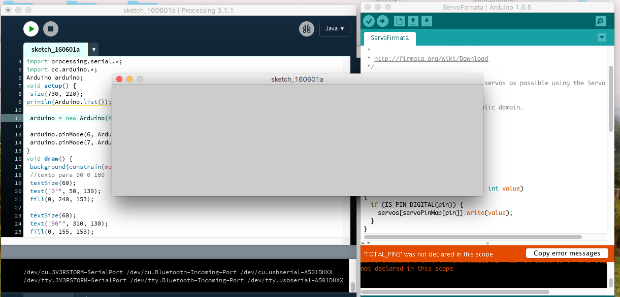
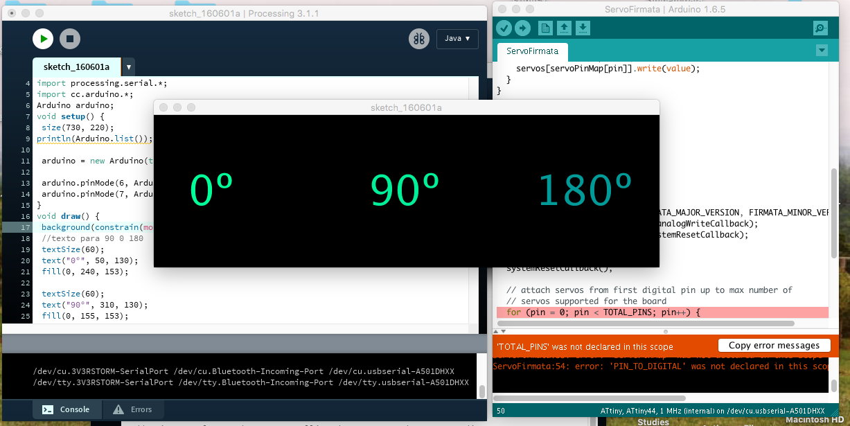
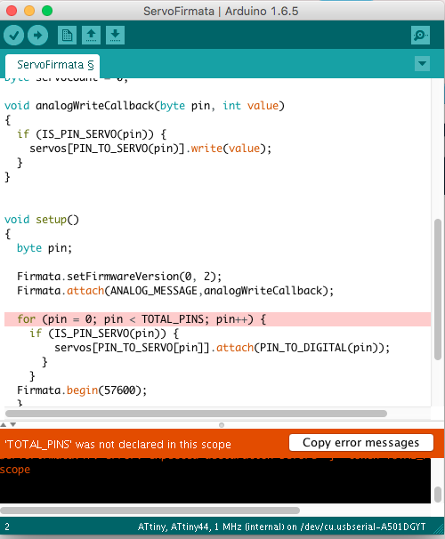
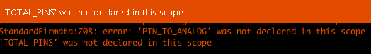
I ran into a problem with this servo process. I was able to get the processing to work, but I kept getting an error message stating the 'TOTAL_PINS' was not declared in the scope. I tried so trouble shooting, but kept getting the same issues. I than moved on to trying the blink code board using the PWM example code. I used the Cyber-Alaska site to learn more about this process and end up using a another example process. This time i tryied the PWM code and prototyped it on an actual Arduino. I found pure success and even made some basic changes. Next, I ran it on my blink hello world board and got the previous error message again. I asked Terence for help, and we realized the issue was that I have a different pink amounts on the ATTINY44 and ATTMEGA328p. You can see this whole process in my images below and video:
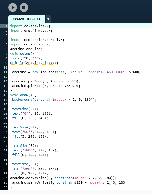
The next step is to use a Fabduino because it has an Attmega328p chip. I did learn how to make changes in processing with regards to colors, sizes, text, shapes and alignments. My prior basic experience with Java helped. I also learned the importance of making sure the serial connections work between the arduino and processing. I will continue working with this process and hope to either have the blink pwm or the servo code work. I did like how processing allows you to interact with a GUI. For example, I was able to make my LEDs fade up or down depending on which direction I moved my mouse across the X axis. I am excited to see the servo motors control the value to be seen in the servo code.
Success
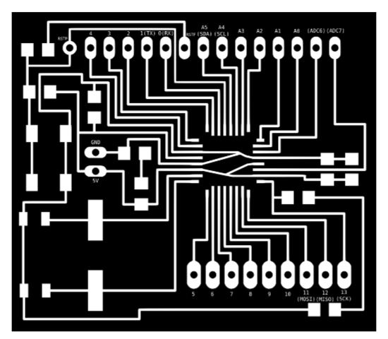
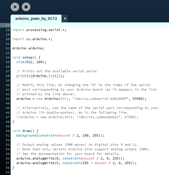
I found success when I ran it on the Fabduino. The design orginal came from satshatkit. I change the pins from 9 and 11 to the analog 5 and 6 to run a PWM code with the light code. I used the layout of the board to help identify the pins. The code worked successfully and I did not get the error message any more. The video below shows my code working successfully. I learned that the 'TOTAL_PINS' code identifies all of the pins for the processing for you. All you need to do know is change the pins in processiong as I already explained.